maintenance DODGE TRUCK 1993 Service Service Manual
[x] Cancel search | Manufacturer: DODGE, Model Year: 1993, Model line: TRUCK, Model: DODGE TRUCK 1993Pages: 1502, PDF Size: 80.97 MB
Page 226 of 1502
BRAKES
5 - 39
DISC BRAKE LINING WEAR COMPENSATION
Normal lining wear is compensated for by exten
sion of the caliper piston and by lateral movement of
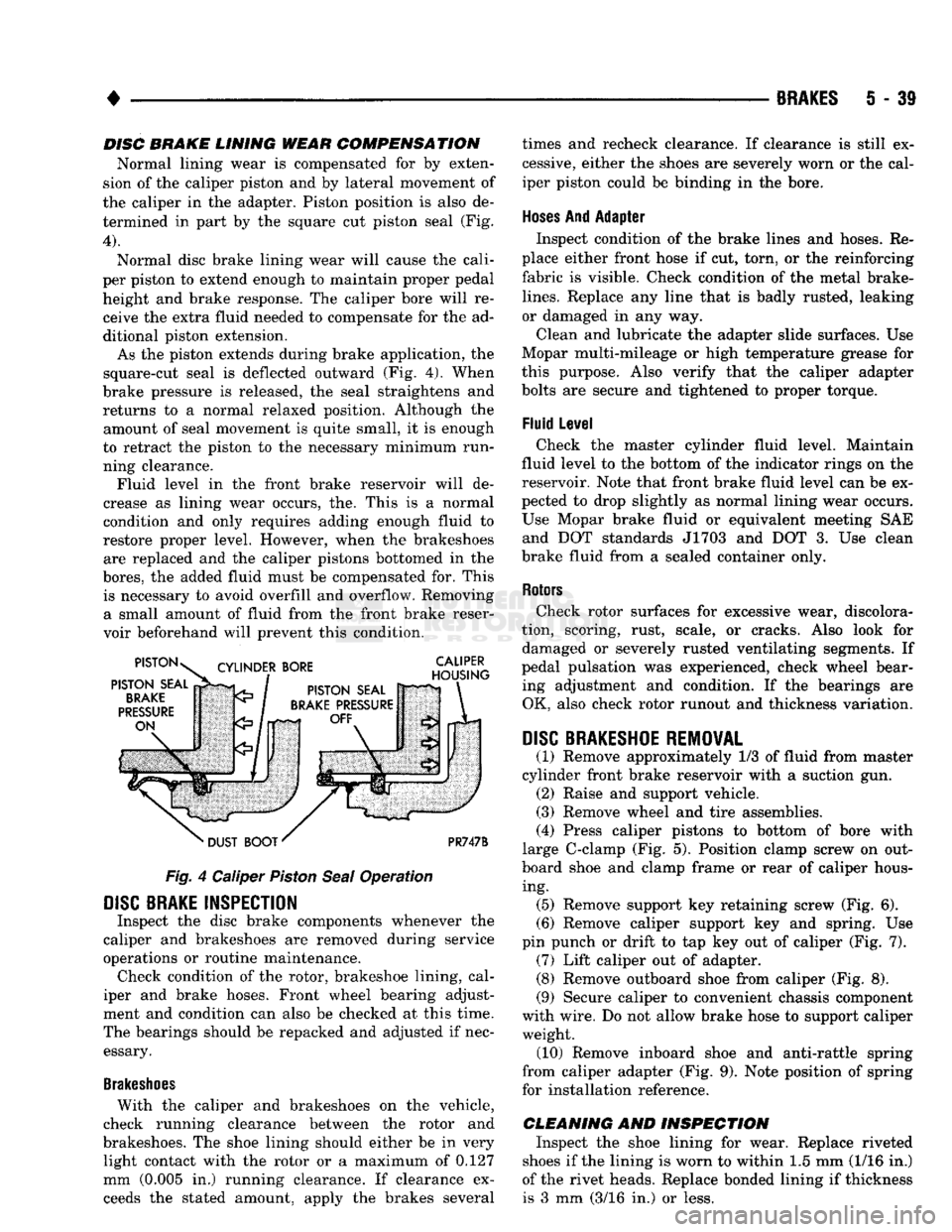
the caliper in the adapter. Piston position is also de termined in part by the square cut piston seal (Fig.
4).
Normal disc brake lining wear will cause the cali
per piston to extend enough to maintain proper pedal height and brake response. The caliper bore will receive the extra fluid needed to compensate for the ad
ditional piston extension.
As the piston extends during brake application, the
square-cut seal is deflected outward (Fig. 4). When
brake pressure is released, the seal straightens and returns to a normal relaxed position. Although the amount of seal movement is quite small, it is enough
to retract the piston to the necessary minimum run ning clearance. Fluid level in the front brake reservoir will de
crease as lining wear occurs, the. This is a normal
condition and only requires adding enough fluid to
restore proper level. However, when the brakeshoes are replaced and the caliper pistons bottomed in the
bores,
the added fluid must be compensated for. This is necessary to avoid overfill and overflow. Removing a small amount of fluid from the front brake reser
voir beforehand will prevent this condition.
Fig.
4 Caliper
Piston
Seal
Operation
DISC
BRAKE INSPECTION
Inspect the disc brake components whenever the
caliper and brakeshoes are removed during service
operations or routine maintenance. Check condition of the rotor, brakeshoe lining, cal
iper and brake hoses. Front wheel bearing adjust
ment and condition can also be checked at this time.
The bearings should be repacked and adjusted if nec essary.
Brakeshoes
With the caliper and brakeshoes on the vehicle,
check running clearance between the rotor and
brakeshoes. The shoe lining should either be in very light contact with the rotor or a maximum of 0.127
mm (0.005 in.) running clearance. If clearance exceeds the stated amount, apply the brakes several times and recheck clearance. If clearance is still ex
cessive, either the shoes are severely worn or the cal
iper piston could be binding in the bore.
Hoses
And Adapter Inspect condition of the brake lines and hoses. Re
place either front hose if cut, torn, or the reinforcing
fabric is visible. Check condition of the metal brake-
lines.
Replace any line that is badly rusted, leaking
or damaged in any way.
Clean and lubricate the adapter slide surfaces. Use
Mopar multi-mileage or high temperature grease for
this purpose. Also verify that the caliper adapter
bolts are secure and tightened to proper torque.
Fluid Level Check the master cylinder fluid level. Maintain
fluid level to the bottom of the indicator rings on the
reservoir. Note that front brake fluid level can be ex
pected to drop slightly as normal lining wear occurs.
Use Mopar brake fluid or equivalent meeting SAE and DOT standards J1703 and DOT 3. Use clean
brake fluid from a sealed container only.
Rotors
Check rotor surfaces for excessive wear, discolora
tion, scoring, rust, scale, or cracks. Also look for damaged or severely rusted ventilating segments. If
pedal pulsation was experienced, check wheel bear ing adjustment and condition. If the bearings are OK, also check rotor runout and thickness variation.
DISC
BRAKESHOE REMOVAL
(1) Remove approximately 1/3 of fluid from master
cylinder front brake reservoir with a suction gun. (2) Raise and support vehicle.
(3) Remove wheel and tire assemblies.
(4) Press caliper pistons to bottom of bore with
large C-clamp (Fig. 5). Position clamp screw on out
board shoe and clamp frame or rear of caliper hous ing. (5) Remove support key retaining screw (Fig. 6).
(6) Remove caliper support key and spring. Use
pin punch or drift to tap key out of caliper (Fig. 7). (7) Lift caliper out of adapter. (8) Remove outboard shoe from caliper (Fig. 8).
(9) Secure caliper to convenient chassis component
with wire. Do not allow brake hose to support caliper weight. (10) Remove inboard shoe and anti-rattle spring
from caliper adapter (Fig. 9). Note position of spring
for installation reference.
CLEANING AND INSPECTION Inspect the shoe lining for wear. Replace riveted
shoes if the lining is worn to within 1.5 mm (1/16 in.)
of the rivet heads. Replace bonded lining if thickness is 3 mm (3/16 in.) or less.
Page 323 of 1502
8A
- 2
ELECTRICAL
•
MALFUNCTION
INDICATOR
LAMP
DIAGNOSTIC SCAN
TOOL
POWERTRAIN CONTROL
MODULE
GENERATOR
BATTERY
J938A-23
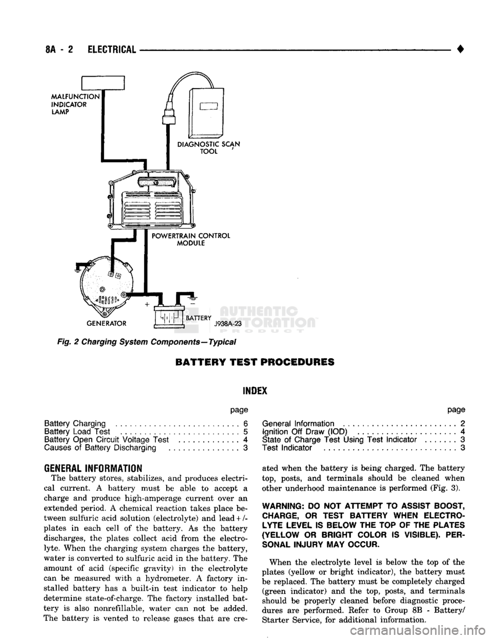
Fig.
2
Charging
System
Components—Typical
BATTERY TEST
PROCEDURES
INDEX
page
Battery
Charging
6
Battery
Load Test
5
Battery
Open
Circuit
Voltage Test
.............
4
Causes
of
Battery
Discharging
3
GENERAL
INFORMATION
The battery stores, stabilizes,
and
produces electri
cal current.
A
battery must
be
able
to
accept
a
charge
and
produce high-amperage current over
an
extended period.
A
chemical reaction takes place
be
tween sulfuric acid solution (electrolyte)
and
lead + /-
plates
in
each cell
of the
battery.
As the
battery discharges,
the
plates collect acid from
the
electro
lyte.
When
the
charging system charges
the
battery,
water
is
converted
to
sulfuric acid
in the
battery.
The
amount
of
acid (specific gravity)
in the
electrolyte
can
be
measured with
a
hydrometer.
A
factory
in
stalled battery
has a
built-in test indicator
to
help
determine state-of-charge.
The
factory installed bat
tery
is
also nonrefillable, water
can not be
added.
The battery
is
vented
to
release gases that
are cre-
page
General
Information
2
Ignition
Off
Draw (IOD)
4
State
of
Charge Test Using Test
Indicator
.......
3
Test
Indicator
3
ated when
the
battery
is
being charged.
The
battery
top,
posts,
and
terminals should
be
cleaned when other underhood maintenance
is
performed (Fig.
3).
WARNING:
DO
NOT
ATTEMPT
TO
ASSIST BOOST, CHARGE,
OR
TEST BATTERY WHEN ELECTROLYTE LEVEL IS BELOW THE TOP
OF
THE PLATES
(YELLOW
OR
BRIGHT COLOR
IS
VISIBLE). PER
SONAL
INJURY
MAY
OCCUR.
When
the
electrolyte level
is
below
the top of the
plates (yellow
or
bright indicator),
the
battery must
be replaced.
The
battery must
be
completely charged (green indicator)
and the top,
posts,
and
terminals
should
be
properly cleaned before diagnostic proce
dures
are
performed. Refer
to
Group
8B -
Battery/ Starter Service,
for
additional information.
Page 324 of 1502
•
ELECTRICAL
8A - 3
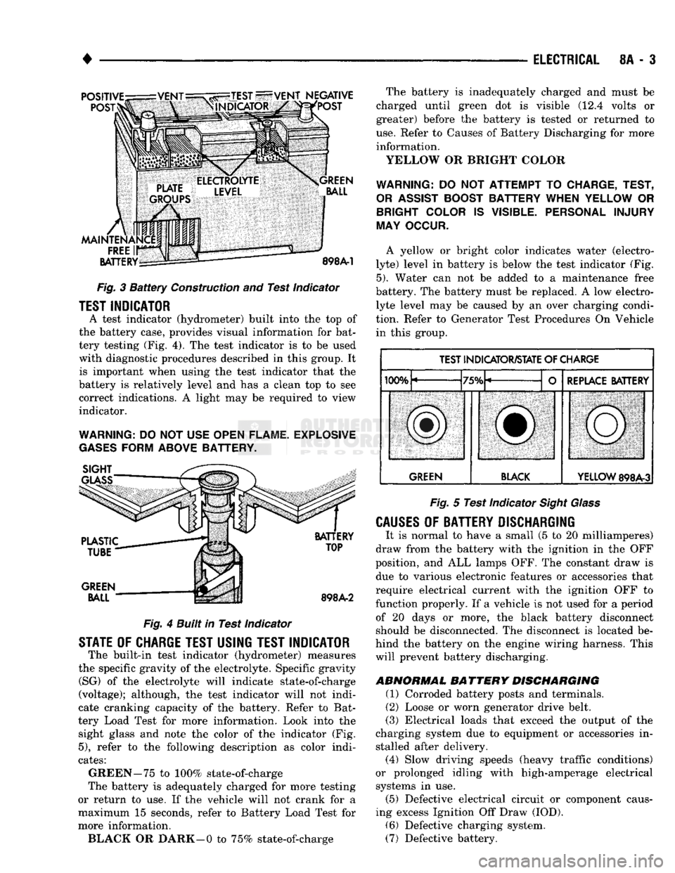
Fig.
3
Battery
Construction
and
Test Indicator
TEST INDICATOR
A test indicator (hydrometer) built into
the top of
the battery case, provides visual information
for
bat
tery testing (Fig.
4). The
test indicator
is to be
used with diagnostic procedures described
in
this group.
It
is important when using
the
test indicator that
the
battery
is
relatively level
and has a
clean
top to see
correct indications.
A
light
may be
required
to
view
indicator.
WARNING:
DO
NOT USE
OPEN FLAME. EXPLOSIVE
GASES
FORM ABOVE BATTERY.
Fig.
4
Built in Test Indicator
STATE
OF
CHARGE TEST USING TEST INDICATOR
The built-in test indicator (hydrometer) measures
the specific gravity
of
the electrolyte. Specific gravity (SG)
of the
electrolyte will indicate state-of-charge
(voltage); although,
the
test indicator will
not
indi
cate cranking capacity
of the
battery. Refer
to
Bat
tery Load Test
for
more information. Look into
the
sight glass
and
note
the
color
of the
indicator
(Fig.
5),
refer
to the
following description
as
color indi
cates:
GREEN-75
to
100% state-of-charge
The battery
is
adequately charged
for
more testing
or return
to use. If the
vehicle will
not
crank
for a
maximum
15
seconds, refer
to
Battery Load Test
for
more information. BLACK
OR
DARK—0
to
75% state-of-charge The battery
is
inadequately charged
and
must
be
charged until green
dot is
visible
(12.4
volts
or
greater) before
the
battery
is
tested
or
returned
to
use.
Refer
to
Causes
of
Battery Discharging
for
more information.
YELLOW
OR
BRIGHT COLOR
WARNING:
DO NOT
ATTEMPT
TO
CHARGE, TEST,
OR
ASSIST
BOOST BATTERY WHEN YELLOW
OR
BRIGHT COLOR
IS
VISIBLE. PERSONAL INJURY
MAY OCCUR.
A yellow
or
bright color indicates water (electro
lyte) level
in
battery
is
below
the
test indicator
(Fig.
5).
Water
can not be
added
to a
maintenance free
battery.
The
battery must
be
replaced.
A low
electro lyte level
may be
caused
by an
over charging condi
tion. Refer
to
Generator Test Procedures
On
Vehicle in this group.
TEST INDICATOR/STATE
OF
CHARGE
IfVW,
"TCfV
REPLACE BATTERY
lUUTu
/Otu L
f
REPLACE BATTERY
SBl
ill,
iMMiMMMMSMM^MM
GREEN BLACK
YELLOW
898A-3
Fig.
5
Test Indicator
Sight Glass
CAUSES
OF
BATTERY DISCHARGING
It
is
normal
to
have
a
small
(5 to 20
milliamperes)
draw from
the
battery with
the
ignition
in the OFF
position,
and ALL
lamps OFF.
The
constant draw
is
due
to
various electronic features
or
accessories that
require electrical current with
the
ignition
OFF to
function properly.
If a
vehicle
is not
used
for a
period of
20
days
or
more,
the
black battery disconnect
should
be
disconnected.
The
disconnect
is
located
be
hind
the
battery
on the
engine wiring harness. This will prevent battery discharging.
ABNORMAL
BATTERY
DISCHARGING
(1) Corroded battery posts
and
terminals.
(2) Loose
or
worn generator drive belt.
(3) Electrical loads that exceed
the
output
of the
charging system
due to
equipment
or
accessories
in
stalled after delivery. (4) Slow driving speeds (heavy traffic conditions)
or prolonged idling with high-amperage electrical systems
in use.
(5) Defective electrical circuit
or
component caus
ing excess Ignition
Off
Draw (IOD).
(6) Defective charging system.
(7) Defective battery.
Page 342 of 1502
• BATTERY/STARTER/GENERATOR
SERVICE
8B - 1
CONTENTS
page page
BATTERY
SERVICE
PROCEDURES
1 SPECIFICATIONS 9
GENERATOR
SERVICE
6 STARTER
SERVICE
PROCEDURES
4
BATTERY SERVICE PROCEDURES
GENERAL
INFORMATION This section will cover the Battery service, re
moval, and installation procedures only. For diagnos
tic procedures, see Group 8A - Battery/Starting/ Charging Systems Diagnostics. The Maintenance Free Battery (Fig. 1) does not
have removable battery cell caps. Water can not be added to this battery. The battery is sealed, except
for small vent holes in the top. The chemical compo sition inside of the battery produces an extremely
small amount of gases at normal charging voltages.
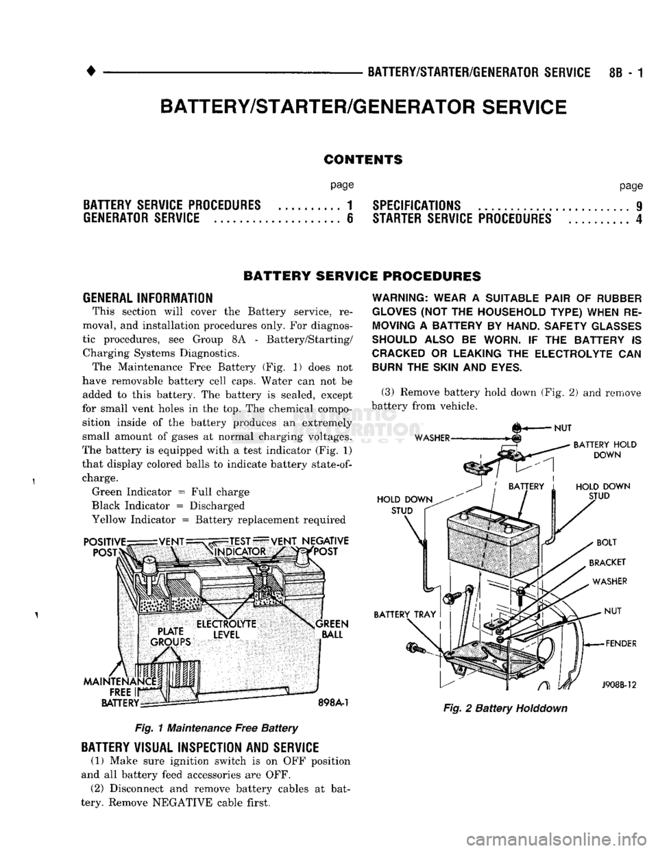
The battery is equipped with a test indicator (Fig. 1)
that display colored balls to indicate battery
state-of-
charge. Green Indicator = Full charge
Black Indicator = Discharged
Yellow Indicator = Battery replacement required Fig. 1 Maintenance Free Battery
BATTERY
VISUAL INSPECTION AND
SERVICE
(1) Make sure ignition switch is on OFF position
and all battery feed accessories are OFF. (2) Disconnect and remove battery cables at bat
tery. Remove NEGATIVE cable first.
WARNING: WEAR
A
SUITABLE PAIR
OF
RUBBER
GLOVES
(NOT THE
HOUSEHOLD TYPE) WHEN
RE
MOVING
A
BATTERY
BY
HAND. SAFETY
GLASSES
SHOULD ALSO
BE
WORN.
IF THE
BATTERY
IS
CRACKED
OR
LEAKING
THE
ELECTROLYTE
CAN
BURN
THE
SKIN
AND
EYES.
(3) Remove battery hold down (Fig. 2) and remove
battery from vehicle. Fig. 2 Battery
Holddown
BATTERY/STARTER/GENERATOR
SERVICE
Page 352 of 1502
•
IGNITION
SYSTEMS
8D
- 1
CONTENTS
page page
COMPONENT IDENTIFICATION/SYSTEM DIAGNOSTICS/SERVICE PROCEDURES
7
OPERATION
1
IGNITION SWITCH
25
COMPONENT REMOVAL/INSTALLATION
..... 18
SPECIFICATIONS
28
COMPONENT
IDENTIFICATION/SYSTEM OPERATION
INDEX
page
Automatic
Shut Down (ASD) Relay
1
Camshaft Position Sensor
2
Crankshaft Position Sensor
2
Distributors
3
Engine Coolant
Temperature
Sensor
...........
4
General
Information
1
page
Ignition
Coil
3
Intake
Manifold Charge
Air
Temperature
Sensor
. . 4
Manifold Absolute Pressure (MAP) Sensor
4
Powertrain
Control
Module (PCM)
. 5
Throttle
Position Sensor
5
GENERAL
INFORMATION
Throughout this group, references
are
made
to
par
ticular vehicle models
by
alphabetical designation
or
by
the
particular vehicle nameplate.
A
chart showing a breakdown
of
alphabetical designations
is
included
in
the
Introduction group
at the
beginning
of
this
manual. 5.9L
gas
powered engines will
be
referred
to as ei
ther: LDC (Light Duty Cycle),
or
HDC (Heavy Duty Cycle). This section
of the
group, Component Identifica
tion/System Operation, will discuss ignition system operation
and
will identify ignition system compo
nents.
For diagnostic procedures
and
adjustments, refer
to
the Diagnostics/Service Procedures section
of
this
group.
For removal
and
installation
of
ignition system
components, refer
to the
Component Removal/Instal
lation section
of
this group. For other useful information, refer
to
On-Board
Di
agnostics
in the
General Diagnosis sections
of
Group
14,
Fuel System
in
this manual. For operation
of the DRB II
Diagnostic Scan Tool,
refer
to the
appropriate Powertrain Diagnostic Proce
dures service manual.
An Ignition specifications section
is
included
at the
end
of
this group.
A
general Maintenance Schedule (mileage intervals)
for
ignition related items
can be
found
in
Group
0,
Lubrication and Maintenance. This
schedule
can
also
be
found
in the
Owners Manual.
IGNITION
SYSTEMS
The ignition systems used
on all
engines
are
basi
cally identical. Similarities
and
differences between
the systems will
be
discussed.
A sequential multi-port fuel injection system
is
used
on all gas
powered engines.
The ignition system
is
controlled
by the
powertrain
control module (PCM)
on all
engines.
The
PCM
was
formerly referred
to as the
SBEC
or
engine control ler.
The ignition system consists
of:
• Spark Plugs
• Ignition Coil
• Secondary Ignition Cables
• Ignition distributor. Contains rotor
and
camshaft
position sensor • Powertrain Control Module (PCM)
• Crankshaft Position Sensor
AUTOMATIC SHUT DOWN (ASD) RELAY
The automatic shut down (ASD) relay
is
located
in
the engine compartment (Fig.
1). As one of its
func
tions,
the ASD
relay will supply battery voltage
to
the ignition coil.
The
ground circuit
for the
ASD
re
lay
is
controlled
by the
powertrain control module (PCM).
The PCM
regulates
ASD
relay operation
by
switching
the
ground circuit on-and-off.
IGNITION
SYSTEMS
Page 365 of 1502
8D
- 14
IGNITION SYSTEMS
• (5) Test the MAP sensor ground circuit at sensor
connector terminal-A (Fig. 19) and PCM connector
terminal-4. Repair the wire harness if necessary.
(6) Test the MAP sensor ground circuit at the
PCM connector between terminal-4 and terminal-11
with an ohmmeter. If the ohmmeter indicates an
open circuit, inspect for a defective sensor ground
connection. Refer to Group 8W, Wiring for location of
this connection. If the ground connection is good, re
place the PCM. If terminal-4 has a short circuit to 12 volts +, correct this condition before replacing the
PCM.
POWERTRAIN
CONTROL MODULE {PCM)
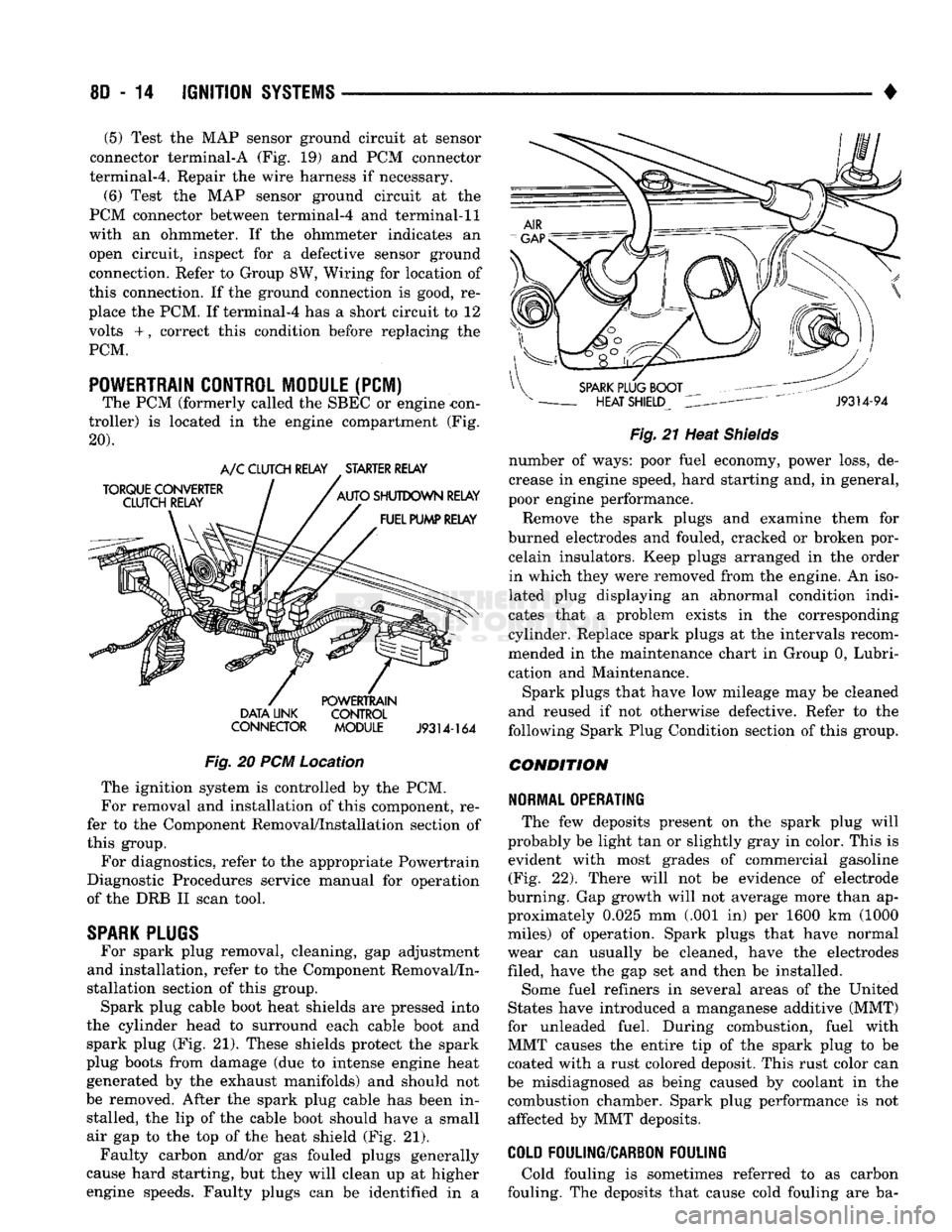
The PCM (formerly called the SBEC or engine -con
troller) is located in the engine compartment (Fig.
20). DATA UNK CONTROL
CONNECTOR MODULE
J9314-164
Fig.
20 PCM Location The ignition system is controlled by the PCM.
For removal and installation of this component, re
fer to the Component Removal/Installation section of
this group.
For diagnostics, refer to the appropriate Powertrain
Diagnostic Procedures service manual for operation
of the DRB II scan tool.
SPARK
PLUGS
For spark plug removal, cleaning, gap adjustment
and installation, refer to the Component Removal/In
stallation section of this group. Spark plug cable boot heat shields are pressed into
the cylinder head to surround each cable boot and
spark plug (Fig. 21). These shields protect the spark
plug boots from damage (due to intense engine heat
generated by the exhaust manifolds) and should not
be removed. After the spark plug cable has been in stalled, the lip of the cable boot should have a small
air gap to the top of the heat shield (Fig. 21). Faulty carbon and/or gas fouled plugs generally
cause hard starting, but they will clean up at higher
engine speeds. Faulty plugs can be identified in a
Fig.
21 Heat
Shields
number of ways: poor fuel economy, power loss, de
crease in engine speed, hard starting and, in general,
poor engine performance.
Remove the spark plugs and examine them for
burned electrodes and fouled, cracked or broken por celain insulators. Keep plugs arranged in the order
in which they were removed from the engine. An iso
lated plug displaying an abnormal condition indi
cates that a problem exists in the corresponding
cylinder. Replace spark plugs at the intervals recom
mended in the maintenance chart in Group 0, Lubri
cation and Maintenance.
Spark plugs that have low mileage may be cleaned
and reused if not otherwise defective. Refer to the
following Spark Plug Condition section of this group.
CONDITION
NORMAL OPERATING
The few deposits present on the spark plug will
probably be light tan or slightly gray in color. This is evident with most grades of commercial gasoline (Fig. 22). There will not be evidence of electrode
burning. Gap growth will not average more than ap proximately 0.025 mm (.001 in) per 1600 km (1000
miles) of operation. Spark plugs that have normal
wear can usually be cleaned, have the electrodes filed, have the gap set and then be installed.
Some fuel refiners in several areas of the United
States have introduced a manganese additive (MMT)
for unleaded fuel. During combustion, fuel with
MMT causes the entire tip of the spark plug to be coated with a rust colored deposit. This rust color can
be misdiagnosed as being caused by coolant in the combustion chamber. Spark plug performance is not affected by MMT deposits.
COLD
FOULING/CARBON FOULING
Cold fouling is sometimes referred to as carbon
fouling. The deposits that cause cold fouling are ba-
Page 384 of 1502
•
INSTRUMENT PANEL
AND
GAUGES
8E - 3
MALFUNCTION INDICATOR (CHECK ENGINE)
Fig.
5
Distance Sensor
If
the
input from
one of the
following sensors fails
an internal Powertrain Control Module
(PCM)
self
check,
the PCM
turns
on the
Check Engine Lamp. The
PCM
then substitutes
a
modified signal
in
place
of
the one
that failed until
a
repair
is
made:
• Manifold Absolute Pressure (MAP) Sensor
• Throttle Position Sensor
• Coolant Temperature Sensor
• Battery Voltage Sense
• Battery Voltage
Too
High
Refer
to the
appropriate Powertrain Diagnostic
Test Procedures manual
for
further information.
ELECTRONIC DIGITAL CLOCK
The electronic digital clock
is in the
radio.
The
clock
and
radio each
use the
display panel built into
the radio.
A
digital readout indicates
the
time
in
hours
and
minutes whenever
the
ignition switch
is in
the
ON or ACC
position. When
the
ignition switch
is in the OFF
position
or
when
the
radio frequency
is
being displayed, time keeping
is
accurately maintained. The procedure
for
setting
the
clock varies slightly
with each radio.
The
correct procedure
is
described under
the
individual radio operating instructions
re
ferred
to in the
Owner Manual supplied with
the ve
hicle.
MESSAGE CENTER—GAS ENGINE
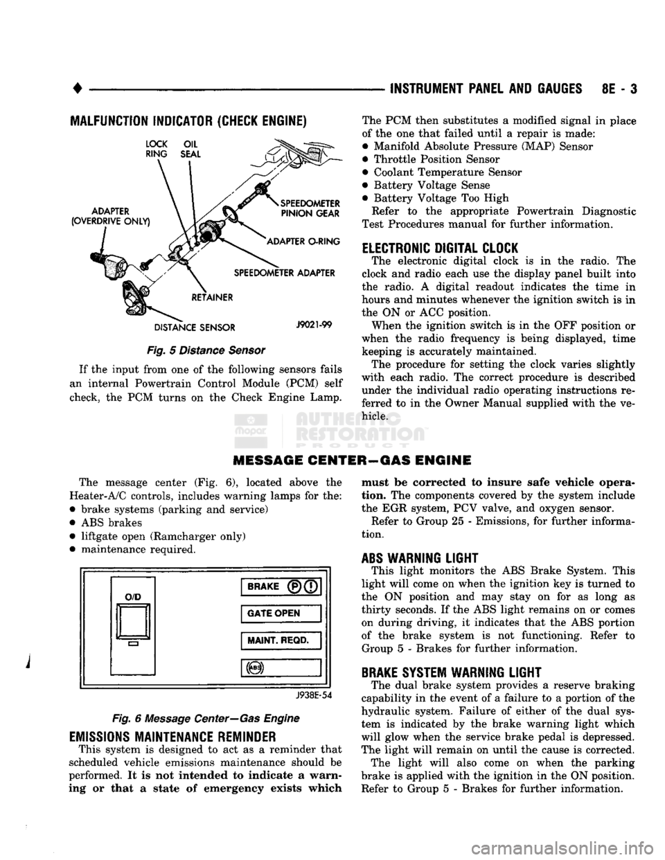
The message center
(Fig. 6),
located above
the
Heater-A/C controls, includes warning lamps
for the:
• brake systems (parking
and
service)
•
ABS
brakes • liftgate open (Ramcharger only)
• maintenance required.
O/D
BRAKE
(P)(7
GATE OPEN
MAINT
REQD.
J938E-54
Fig.
6
Message Center—Gas Engine
EMISSIONS
MAINTENANCE REMINDER
This system
is
designed
to act as a
reminder that
scheduled vehicle emissions maintenance should
be
performed.
It is not
intended
to
indicate
a
warn
ing
or
that
a
state
of
emergency exists which must
be
corrected
to
insure safe vehicle opera
tion.
The
components covered
by the
system include
the
EGR
system,
PCV
valve,
and
oxygen sensor. Refer
to
Group
25 -
Emissions,
for
further informa
tion.
ABS
WARNING
LIGHT
This light monitors
the ABS
Brake System. This
light will come
on
when
the
ignition
key is
turned
to
the
ON
position
and may
stay
on for as
long
as
thirty seconds.
If the ABS
light remains
on or
comes on during driving,
it
indicates that
the ABS
portion
of
the
brake system
is not
functioning. Refer
to
Group
5 -
Brakes
for
further information.
BRAKE
SYSTEM WARNING
LIGHT
The dual brake system provides
a
reserve braking
capability
in the
event
of a
failure
to a
portion
of the
hydraulic system. Failure
of
either
of the
dual sys
tem
is
indicated
by the
brake warning light which
will glow when
the
service brake pedal
is
depressed.
The light will remain
on
until
the
cause
is
corrected. The light will also come
on
when
the
parking
brake
is
applied with
the
ignition
in the ON
position.
Refer
to
Group
5 -
Brakes
for
further information.
Page 454 of 1502

•
LAMPS
8L - 11
BULB
APPLICATION
GENERAL
INFORMATION
The following Bulb Application Table lists
the
lamp title
on the
left side
of the
column
and
part
number
on the
right.
CAUTION:
Do not use
bulbs
that
have
a
higher
can
dle power than
the
bulb
listed
in the
Bulb
Applica
tion Table.
Damage
to
lamp
can
result.
EXTERIOR LAMPS
Auxiliary Turn Signal (Snow Plow) 2057
Auxiliary Headlamps (Snow Plow) .6054
Back-up....................... .......1156 Cargo Lamp..
922
Clearance Lamps
194
Front Side Marker
168
Headlamp/Sealed Beam .6052
License Plate
168
Park/Turn Signal 2057
TaiyStop/Turn Signal ...2057
INTERIOR LAMPS
DIMMER CONTROLLED LAMPS Service procedures
for
most
of the
lamps
in the in
strument panel
are
located
in
Group
8E,
Instrument
Panel
and
Gauges. Some components have lamps
that
can
only
be
serviced
by an
Authorized Service Center (ASC). These components must
be
removed
from
the
vehicle
for
service. Contact local dealer
for
location
of
nearest
ASC.
A/C Heater Control
158
Ash Receiver
..158
Gear Shift Selector...........................................PC194
Heater Control
158
Instrument Cluster.. PC 194
Radio
ASC
Snow Plow Control
.158
INDICATOR LAMPS Service procedures
for
most
of the
lamps
in the in
strument panel,
and
switches
are
located
in
Group
8E,
Instrument Panel
and
Gauges. Anti-lock Brake PC194
Brake Warning PC194 Check Engine PC194
Engine
Oil
Pressure
158
Fasten Seat Belts.. PC 194 Four Wheel Drive ....158
Hazard Flasher
194
High Beam PC194
Low Fuel....... JPC194
Maintenance Required PC 194
Transmission Temperature ..PC 194 Turn Signal PC194
NON-DIMMING LAMPS Service procedures
for
most
of the
lamps
in the
fol
lowing list
can be
found
in
Group
23,
Body.
Dome
1004
Engine Compartment ...105 Glove Compartment....
1891
Ignition Lock
ASC
Reading Lamp
912
Page 607 of 1502
9
- 2
ENGINES
rial surrounds each mounting hole. Excess material
can easily be wiped off. Components should be
torqued in place within 15 minutes. The use of a lo cating dowel is recommended during assembly to pre
vent smearing the material off location.
ENGINE PERFORMANCE
To provide best vehicle performance and lowest ve
hicle emissions, it is most important that the tune-up
be done accurately. Use the specifications listed on
the Vehicle Emission Control Information label found on the engine compartment hood.
(1) Test cranking amperage draw (refer to Group
8B,
Battery/Starter/Generator Service for the proper
procedures).
(2) Tighten the intake manifold bolts (refer to
Group 11, Exhaust System and Intake Manifold for
the proper specifications). (3) Perform cylinder compression test:
(a) Check engine oil level and add oil, if neces
sary.
(b) Drive the vehicle until engine reaches normal
operating temperature. (c) Select a route free from traffic and other
forms of congestion, observe all traffic laws and
briskly accelerate through the gears several times. The higher engine speed may help clean out valve seat deposits which can prevent accurate compres
sion readings.
CAUTION:
DO NOT
overspeed
the
engine.
(d) Remove all spark plugs from engine. As
spark plugs are being removed, check electrodes for
abnormal firing indicators - fouled, hot, oily, etc.
Record cylinder number of spark plug for future
reference.
(e) Disconnect coil wire from distributor and se
cure to good ground to prevent a spark from start
ing a fire.
(f) Be sure throttle blades are fully open during
the compression check. (g) Insert compression gage adaptor into the
No.l spark plug hole. Crank engine until maxi
mum pressure is reached on gauge. Record this
pressure as No.l cylinder pressure.
(h) Repeat Step 3g for all remaining cylinders.
(i) Compression should not be less than 689 kPa
(100 psi) and not vary more than 172 kPa (25 psi)
from cylinder to cylinder.
(j) If cylinder(s) have abnormally low compres
sion pressures, repeat steps 3a through 3h. (k) If the same cylinder(s) repeat an abnormally
low reading, it could indicate the existence of a
problem in the cylinder.
The recommended compression pressures are
to be used only as a guide to diagnosing engine
problems. An engine should NOT be disassem bled to determine the cause of low compression
unless some malfunction is present. (4) Clean or replace spark plugs as necessary. Ad
just gap (refer to Group 8D, Ignition System for gap adjustment and torque).
(5) Test resistance of spark plug cables (refer to
Group 8D, Ignition System.
(6) Inspect the primary wire. Test coil output volt
age,
primary and secondary resistance. Replace parts as necessary (refer to Group 8D, Ignition System and
make necessary adjustment).
(7) Set ignition timing to specifications (refer to
Specification Label on engine compartment hood).
(8) Perform a combustion analysis.
(9) Test fuel pump for pressure and vacuum (refer
to Group 14, Fuel System for the proper specifica
tions).
(10) Inspect air filter element (refer to Group 0,
Lubrication and Maintenance for the proper proce
dure).
(11) Inspect crankcase ventilation system (refer to
Group 0, Lubrication and Maintenance for the proper
procedure).
(12) For emission controls refer to Group 25, Emis
sion Controls System for service procedures.
(13) Inspect and adjust accessory belt drives (refer
to Group 7, Cooling System for the proper adjust
ments).
(14) Road test vehicle as a final test.
H0NIN6
CYLINDER
BORES
Before honing, stuff plenty of clean shop towels un
der the bores and over the crankshaft to keep abra sive materials from entering the crankshaft area.
(1) Used carefully, the Cylinder Bore Sizing Hone
C-823 equipped with 220 grit stones, is the best tool
for this job. In addition to deglazing, it will reduce
taper and out-of-round as well as removing light scuffing, scoring or scratches. Usually a few strokes
will clean up a bore and maintain the required lim
its.
CAUTION:
DO NOT use rigid type
hones
to remove
cylinder
wall
glaze.
(2) Deglazing of the cylinder walls may be done if
the cylinder bore is straight and round. Use a cylin
der surfacing hone, Honing Tool C-3501, equipped
with 280 grit stones (C-3501-3810). 20-60 strokes, de
pending on the bore condition, will be sufficient to
provide a satisfactory surface. Using honing oil C-3501-3880 or a light honing oil available from ma
jor oil distributors.
CAUTION:
DO NOT use engine or
transmission
oil, mineral
spirits
or
kerosene.
Page 609 of 1502
9
- 4 ENGINES
•
RN861
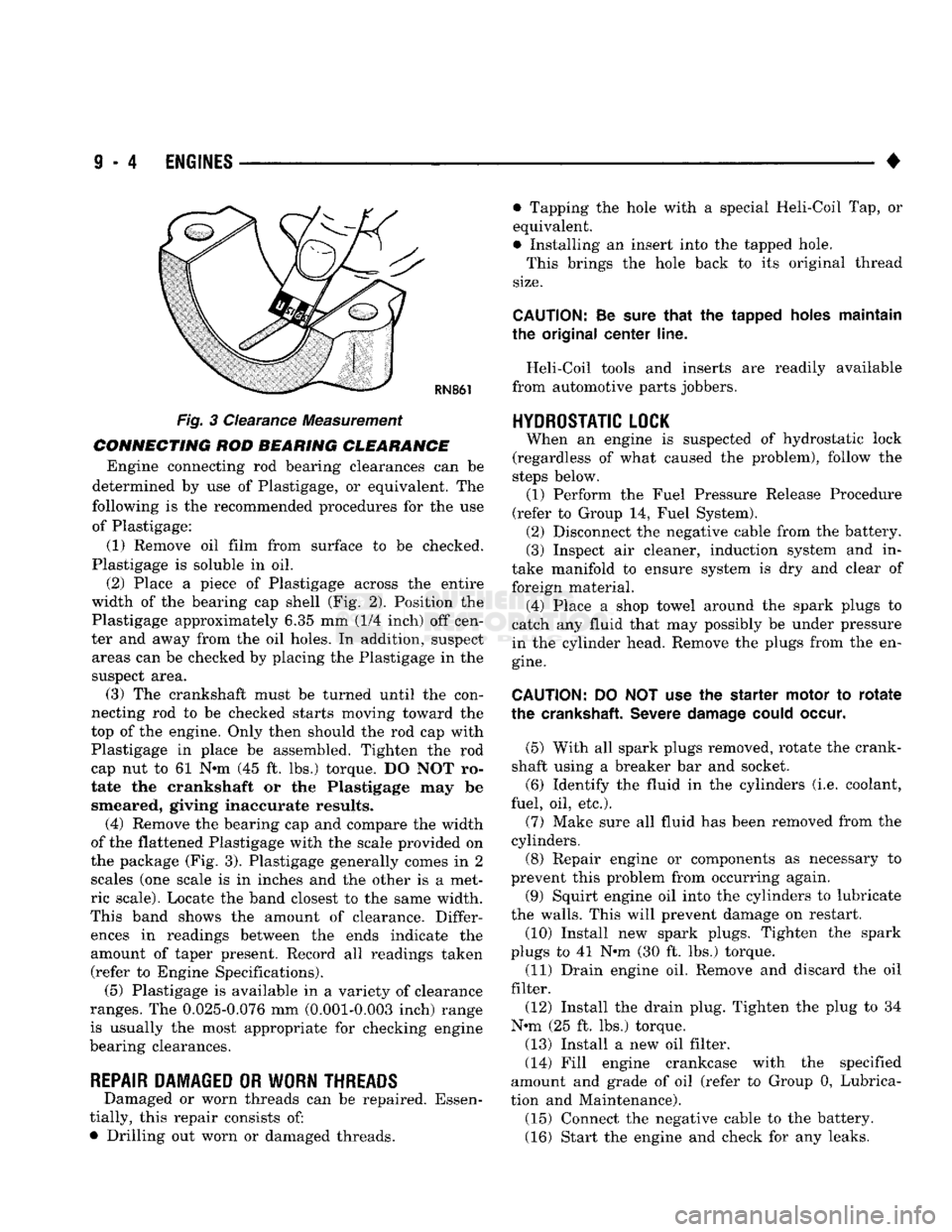
Fig. 3 Clearance Measurement
CONNECTING ROD BEARING CLEARANCE Engine connecting rod bearing clearances can be
determined by use of Plastigage, or equivalent. The
following is the recommended procedures for the use of Plastigage:
(1) Remove oil film from surface to be checked.
Plastigage is soluble in oil.
(2) Place a piece of Plastigage across the entire
width of the bearing cap shell (Fig. 2). Position the
Plastigage approximately 6.35 mm (1/4 inch) off cen
ter and away from the oil holes. In addition, suspect areas can be checked by placing the Plastigage in the
suspect area. (3) The crankshaft must be turned until the con
necting rod to be checked starts moving toward the
top of the engine. Only then should the rod cap with
Plastigage in place be assembled. Tighten the rod
cap nut to 61 Nnn (45 ft. lbs.) torque. DO NOT ro
tate the crankshaft or the Plastigage may be smeared, giving inaccurate results. (4) Remove the bearing cap and compare the width
of the flattened Plastigage with the scale provided on
the package (Fig. 3). Plastigage generally comes in 2 scales (one scale is in inches and the other is a met
ric scale). Locate the band closest to the same width.
This band shows the amount of clearance. Differ ences in readings between the ends indicate the
amount of taper present. Record all readings taken (refer to Engine Specifications). (5) Plastigage is available in a variety of clearance
ranges. The 0.025-0.076 mm (0.001-0.003 inch) range
is usually the most appropriate for checking engine
bearing clearances.
REPAIR DAMAGED OR WORN THREADS Damaged or worn threads can be repaired. Essen
tially, this repair consists of:
• Drilling out worn or damaged threads. • Tapping the hole with a special Heli-Coil Tap, or
equivalent.
• Installing an insert into the tapped hole.
This brings the hole back to its original thread
size.
CAUTION:
Be
sure
that
the tapped holes maintain
the original
center
line.
Heli-Coil tools and inserts are readily available
from automotive parts jobbers.
HYDROSTATIC
LOCK
When an engine is suspected of hydrostatic lock
(regardless of what caused the problem), follow the
steps below. (1) Perform the Fuel Pressure Release Procedure
(refer to Group 14, Fuel System). (2) Disconnect the negative cable from the battery.
(3) Inspect air cleaner, induction system and in
take manifold to ensure system is dry and clear of
foreign material. (4) Place a shop towel around the spark plugs to
catch any fluid that may possibly be under pressure
in the cylinder head. Remove the plugs from the en
gine.
CAUTION:
DO NOT use the starter motor to
rotate
the
crankshaft.
Severe
damage
could
occur.
(5) With all spark plugs removed, rotate the crank
shaft using a breaker bar and socket.
(6) Identify the fluid in the cylinders (i.e. coolant,
fuel, oil, etc.).
(7) Make sure all fluid has been removed from the
cylinders. (8) Repair engine or components as necessary to
prevent this problem from occurring again.
(9) Squirt engine oil into the cylinders to lubricate
the walls. This will prevent damage on restart.
(10) Install new spark plugs. Tighten the spark
plugs to 41 N#m (30 ft. lbs.) torque. (11) Drain engine oil. Remove and discard the oil
filter.
(12) Install the drain plug. Tighten the plug to 34
N-m (25 ft. lbs.) torque.
(13) Install a new oil filter.
(14) Fill engine crankcase with the specified
amount and grade of oil (refer to Group 0, Lubrica
tion and Maintenance). (15) Connect the negative cable to the battery.
(16) Start the engine and check for any leaks.