maintenance DODGE TRUCK 1993 Service Manual PDF
[x] Cancel search | Manufacturer: DODGE, Model Year: 1993, Model line: TRUCK, Model: DODGE TRUCK 1993Pages: 1502, PDF Size: 80.97 MB
Page 1131 of 1502
21
-
130
IN-VEHICLE
SERVICE-~32RH/36RH/37RH/42RH/4iRH
•
IN-VEHICLE
SERVICE-32RH/36RH/37RH/42RH/46RH
INDEX
page
Aluminum Thread Repair
141
Checking
Fluid
Level
130
Extension Housing Bushing
and
Output
Shaft
Bearing
Service-32RH/36RH/37RH
... .
135
Extension Housing Yoke Seal Replacement
....
135
Fluid
and Filter
Change
130
Front
Band
Adjustment
133
Gearshift Linkage
Adjustment
130
Governor
and
Park Gear Service—
32RH/36RH/37RH
137
Governor
and
Park Lock Service—42RH/46RH
.
138
CHECKING
FLUID LEVEL
(1) Position vehicle
on
level surface. This
is ex
tremely important
for
accurate check.
(2)
Apply parking brakes
and run
engine
at
curb
idle speed.
(3)
Shift transmission momentarily into
all
gear
ranges. Then shift back
to
Neutral.
(4)
Clean
top of
filler tube
and
dipstick
(to
avoid
dirt entry)
and
check fluid level. Correct level
is as
follows:
(5)
Be
sure fluid
is at
normal operating tempera
ture (180°F). Correct level
is
between "Maximum Level
Hot"
and
"Add"
marks (crosshatched area)
on
dipstick. (6)
If
fluid level
is
low,
add
only enough fluid
to
correct level.
CAUTION:
Do not
overfill
the
transmission. Overfilling
will
force fluid
out
the
pump vent which
can
be
mistaken
for
a
pump seal leak. Overfilling
will
also
cause
fluid aeration
and foaming
when
the
excess
fluid
is
picked
up
and
churned
by
the
gear train. Aeration
will
reduce fluid
life
significantly.
FLUID
AND
FILTER
CHANGE
Normal Change
Interval
The fluid
and
filter should
be
changed
(and the
bands adjusted)
at
recommended maintenance inter
vals.
Or
whenever
the
transmission
has
been disassembled
for
any
reason.
Recommended Fluid
The recommended
(and
preferred) fluid
for
Chrysler automatic transmissions
is
Mopar
ATF
Plus,
type
7176.
Use
Mopar Dexron
II
only when
ATF Plus
is not
readily available.
page
Park Lock
Service-32RH/36RH/37RH
. 138
Park/Neutral Position Switch
134
Rear
Band
Adjustment
133
Speedometer Service
134
Transmission Cooler Service
140
Transmission
Throttle
Cable
Adjustment-
Cummins Diesel Engine
132
Transmission
Throttle
Cable
Adjustment-
Gas
Engines
131
Valve Body
Control
Pressure Adjustments
.....
140
Valve Body Service
138
Severe Usage Change
Interval
Under severe usage,
the
fluid
and
filter should
be
changed
and the
bands adjusted
at
12,000 mile (19,000
km)
intervals.
Severe usage
is
defined
as:
• More than half
of
vehicle operation occurs
in
heavy city traffic during
hot
weather
at
ambient
temperatures above
90°
F.
• Vehicle
is
used
for
Taxi, Police, Limousine,
or
sim
ilar commercial operations.
• Vehicle
is
used
for
trailer/boat towing
or
heavy
load hauling. When
the
factory fluid
is
drained, refill
the
trans
mission with Mopar
ATF
Plus, type
7176
fluid.
Mo
par Dexron
II
can
be
used
if
ATF
Plus
is
not
readily available.
FLUID
AND
FILTER
REPLACEMENT
PROCEDURE
(1) Raise vehicle, remove
oil pan
and
drain fluid.
(2) Remove filter screws
and
remove filter.
(3) Position
new
filter
on
valve body
and
install fil
ter screws finger tight. (4) Tighten filter screws
to 4
N*m (35
in.
lbs.)
with
torque wrench.
(5) Position
new
gasket
on oil pan
and
install
pan
on transmission. Tighten
pan
bolts
to 17
N»m
(150
in.
lbs.)
torque. (6) Lower vehicle
and
refill transmission with rec
ommended fluid.
GEARSHIFT LINKAGE ADJUSTMENT
Check linkage adjustment
by
starting
the
engine
in Park
and
Neutral. Adjustment
is
OK
if
the
engine starts only
in
park
and Neutral. Adjustment
is
incorrect
if
the
engine starts
in one
but
not
both positions. If
the
engine starts
in
any
position other than Park
or Neutral,
or if
the
engine will
not
start
at
all,
the
park/neutral position switch
may
be
faulty.
Page 1343 of 1502
21
- 342
NP205 TRANSFER CASE
•
NP205
TRANSFER CASE
INDEX
page
General
Information
342
Recommended Lubricants
342
Service Diagnosis
342
Shift
Linkage
Adjustment
344
Speedometer Service
345
GENERAL
INFORMATION
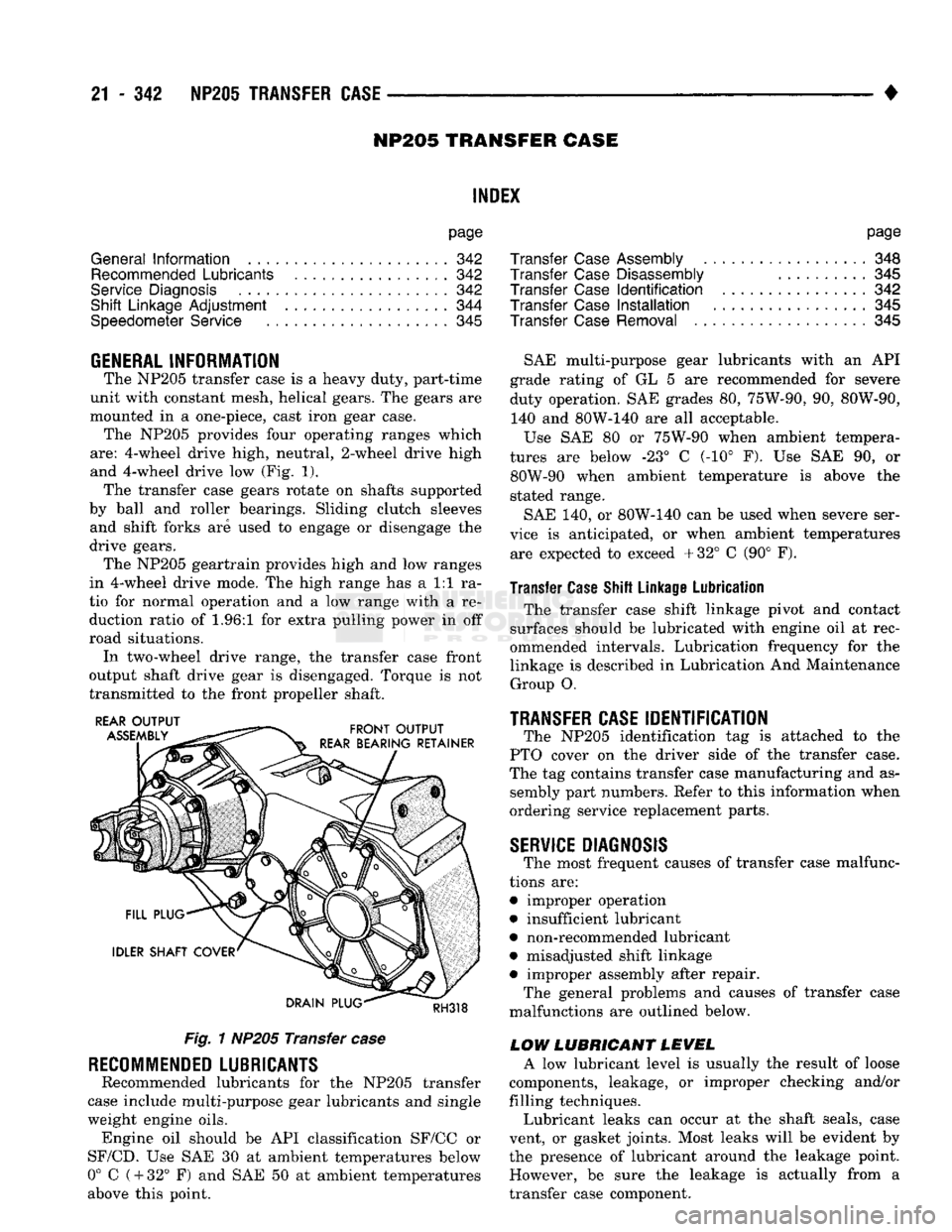
The NP205 transfer case
is a
heavy duty, part-time
unit with constant mesh, helical gears.
The
gears
are
mounted
in a
one-piece, cast iron gear case. The NP205 provides four operating ranges which
are:
4-wheel drive high, neutral, 2-wheel drive high
and 4-wheel drive
low (Fig. 1).
The transfer case gears rotate
on
shafts supported
by ball
and
roller bearings. Sliding clutch sleeves and shift forks
are
used
to
engage
or
disengage
the
drive gears. The NP205 geartrain provides high
and low
ranges
in 4-wheel drive mode.
The
high range
has a 1:1 ra
tio
for
normal operation
and a low
range with
a re
duction ratio
of 1.96:1 for
extra pulling power
in off
road situations. In two-wheel drive range,
the
transfer case front
output shaft drive gear
is
disengaged. Torque
is not
transmitted
to the
front propeller shaft.
Fig.
1
NP205 Transfer
case
RECOMMENDED
LUBRICANTS
Recommended lubricants
for the
NP205 transfer
case include multi-purpose gear lubricants
and
single
weight engine oils. Engine
oil
should
be API
classification SF/CC
or
SF/CD.
Use SAE 30 at
ambient temperatures below
0°
C
(
+
32°
F) and SAE 50 at
ambient temperatures
above this point.
page
Transfer
Case
Assembly
348
Transfer
Case
Disassembly
..........
345
Transfer
Case
Identification
342
Transfer
Case
Installation
345
Transfer
Case
Removal
345
SAE multi-purpose gear lubricants with
an API
grade rating
of GL 5 are
recommended
for
severe
duty operation.
SAE
grades
80,
75W-90,
90,
80W-90, 140
and
80W-140
are all
acceptable.
Use
SAE 80 or
75W-90 when ambient tempera
tures
are
below
-23° C (-10° F). Use SAE 90, or
80W-90 when ambient temperature
is
above
the
stated range.
SAE
140, or
80W-140
can be
used when severe ser
vice
is
anticipated,
or
when ambient temperatures are expected
to
exceed +32°
C (90° F).
Transfer Case Shift Linkage Lubrication
The transfer case shift linkage pivot
and
contact
surfaces should
be
lubricated with engine
oil at
rec
ommended intervals. Lubrication frequency
for the
linkage
is
described
in
Lubrication
And
Maintenance Group
O.
TRANSFER CASE
IDENTIFICATION
The NP205 identification
tag is
attached
to the
PTO cover
on the
driver side
of the
transfer case.
The
tag
contains transfer case manufacturing
and as
sembly part numbers. Refer
to
this information when
ordering service replacement parts.
SERVICE
DIAGNOSIS
The most frequent causes
of
transfer case malfunc
tions
are:
• improper operation
• insufficient lubricant
• non-recommended lubricant
• misadjusted shift linkage
• improper assembly after repair. The general problems
and
causes
of
transfer case
malfunctions
are
outlined below.
LOW LUBRICANT LEVEL
A
low
lubricant level
is
usually
the
result
of
loose
components, leakage,
or
improper checking and/or
filling techniques. Lubricant leaks
can
occur
at the
shaft seals, case
vent,
or
gasket joints. Most leaks will
be
evident
by
the presence
of
lubricant around
the
leakage point. However,
be
sure
the
leakage
is
actually from
a
transfer case component.
Page 1351 of 1502
21 - 350 NP241
TRANSFER CASE
• NP241 TRANSFER CASE
INDEl
page
Checking
Fluid
Level
351
Component Cleaning
and
Inspection
359
Fluid
Drain/Refill
351
General
Information
350
Recommended
Lubricant
.................. 350
Service
Diagnosis
....................... 350
Shift
Linkage
Adjustment
354
Speedometer Adapter/Distance
Sensor
Service
. 352
page
Speedometer Gear, Shaft
Seal,
Bearing
and
Retainer
Service
352
Transfer
Case
Assembly
.................. 361
Transfer
Case
Bearing Replacement
......... 360
Transfer
Case
Disassembly
................ 356
Transfer
Case
Identification ................ 350
Transfer
Case
Installation
................. 356
Transfer
Case
Removal
356
GENERAL
INFORMATION
The NP241 is a part-time transfer case with a low-
range gear system. It has three operating ranges
plus a Neutral position. The low range system pro vides a gear reduction ratio for increased low speed
torque capability. NP241 operating ranges are: 2-high, 4-high and 4-low. The NP241 has an aluminum, two-piece gear case.
Drive sprockets and an interconnecting drive chain are used to transmit engine torque to the propeller
shafts.
Four-wheel high and low ranges are undifferenti
ated. The transfer case is not designed for continuous
operation in 4WD range on hard or paved surfaces.
Four wheel drive ranges are recommended for off
road operation, or on snow covered or similar low
traction surfaces. A front axle disconnect system is used to achieve
two-wheel drive mode. The axle disconnect vacuum motor is actuated by a vacuum switch on the transfer
case.
The switch is operated by the transfer case
range rod. Two-wheel drive range is used for on road, high
way operation. The four-wheel drive ranges are for off road operation or when the vehicle is driven on
paved road surfaces covered by snow, ice or similar low traction elements.
TRANSFER CASE
IDENTIFICATION
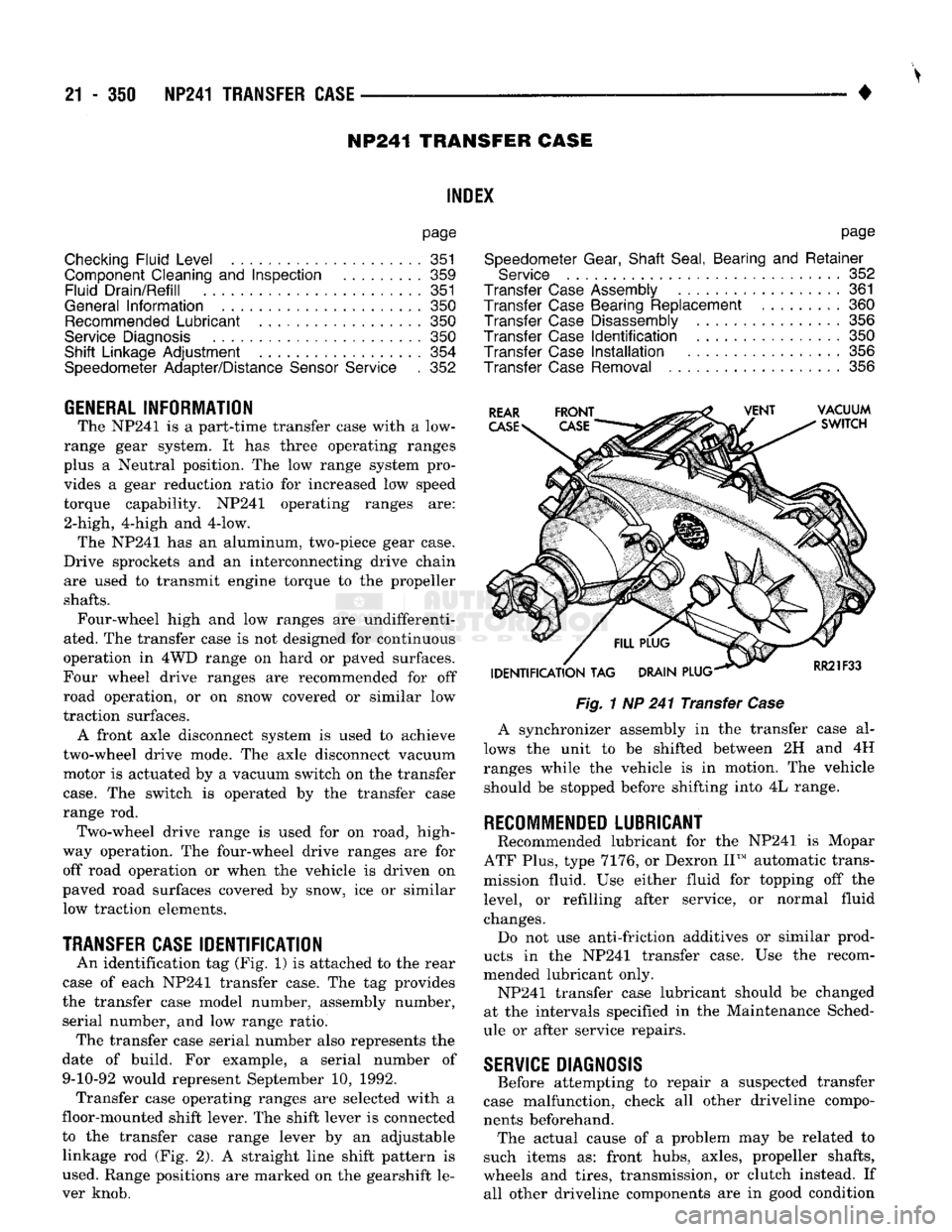
An identification tag (Fig, 1) is attached to the rear
case of each NP241 transfer case. The tag provides
the transfer case model number, assembly number, serial number, and low range ratio. The transfer case serial number also represents the
date of build. For example, a serial number of 9-10-92 would represent September 10, 1992. Transfer case operating ranges are selected with a
floor-mounted shift lever. The shift lever is connected
to the transfer case range lever by an adjustable linkage rod (Fig. 2). A straight line shift pattern is
used. Range positions are marked on the gearshift le
ver knob.
Fig.
1 NP 241 Transfer
Case
A synchronizer assembly in the transfer case al
lows the unit to be shifted between 2H and 4H
ranges while the vehicle is in motion. The vehicle should be stopped before shifting into 4L range.
RECOMMENDED
LUBRICANT
Recommended lubricant for the NP241 is Mopar
ATF Plus, type 7176, or Dexron II™ automatic trans
mission fluid. Use either fluid for topping off the
level, or refilling after service, or normal fluid
changes. Do not use anti-friction additives or similar prod
ucts in the NP241 transfer case. Use the recom
mended lubricant only. NP241 transfer case lubricant should be changed
at the intervals specified in the Maintenance Sched
ule or after service repairs.
SERVICE
DIAGNOSIS
Before attempting to repair a suspected transfer
case malfunction, check all other driveline compo
nents beforehand. The actual cause of a problem may be related to
such items as: front hubs, axles, propeller shafts,
wheels and tires, transmission, or clutch instead. If all other driveline components are in good condition
Page 1448 of 1502

HEATING
AND
AIR
CONDITIONING
24 -
TEMPERATURE
IN
TEST AREA
21-29° C
(70-85°
F)
VERIFY R-12 CHARGE-CONNECT MANIFOLD GAUGES
SEE
MAINTENANCE AND ADJUSTMENTS SECTION
IF
R-12
CHARGE
IS
LOW, CORRECT LEAK, EVACUATE, AND CHARGE SYSTEM
BYPASS
CYCLING CLUTCH SWITCH USING JUMPER WIRE REFER
TO
GROUP
8W,
WIRING DIAGRAMS
START ENGINE ADJUST IDLE
TO 1000
rpm
IN
PARK OR NEUTRAL
WITH
PARK BRAKE SET LOCATE AND REMOVE BOTH
VACUUM LINES AT RECIRC DOOR ACTUATOR INSTALL
LT-GN LINE WHERE DK-GN LINE HAD BEEN
CLOSE
PASSENGER COMPARTMENT
SET
CONTROL TO A/C, PANEL, HIGH BLOWER, FULL HEAT
ENGINE
RPM BLOWER
MOTOR
SPEED
I
EVAPORATOR
I
SUCTION GAUGE
I
PSIG
(kPag)
1
COMPRESSOR
DISCHARGE
GAUGE
PSIG
(kPag)
2
—m
POSSIBLE
I
CAUSE
I
20-35
PSIG
140-240
PSIG
1000 —
HI
(140 TO 240
kPag)
(966
TO
1656
kPag)
i
— NORMAL
Cr a
FREEZE
H-VALVE 15 INCHES
OF VACUUM
THAW
H-VALVE 38 PSIG
(262
kPag)
OR MORE THEN
DROPS
TO 25 TO 35
PSIG
(172
TO
240
kPag)
RETURN RECIRC DOOR VACUUM LINES
TO
NORMAL a
1000
HI
20 30
PSIG
(140 TO 207
kPag)
H240
PSIG OR HIGHER
(1656
kPag)
20-30
PSIG
(140-207
kPag)
140
PSIG
(966
kPag)
OR
LESS
H-VALVE
STUCK OPEN
IF
CONDITIONS
CANNOT BE MET
H-VALVE
STUCK CLOSED
IF
CONDITIONS
CANNOT BE MET
RESTRICTED
CONDENSER-
RESTRICTED
DISCHARGE
LINE
-RADIATOR
OVERHEATING-
AIR
IN
SYSTEM- OVERCHARGED
SYSTEM-COOLING FAN INOP.
RECONNECT LOW PRESSURE/CYCLING SWITCH AND RECONNECT THE VACUUM LINES
TO
THE RECIRC/ACUATOR DEFECTIVE
COMPRESSOR
HEAD
GASKET
OR
DISCHARGE
REEDS
J9124-104
AIR
CONDITIONING REFRIGERANT SYSTEM DIAGNOSIS
Page 1478 of 1502
•
EMISSION
CONTROL
SYSTEMS
25
- 1
CONTENTS
page page
AIR INJECTION
SYSTEM-o
9L
HDC-GAS EVAPORATIVE EMISSION CONTROLS
6
ENGINE
15
EXHAUST EMISSION CONTROLS
10
COMPONENT
REMOVAL/INSTALLATION
17
GENERAL INFORMATION
1
GENERAL
INFORMATION
Throughout this group, references are made
to
par
ticular vehicle models
by
alphabetical designation
or
by the particular vehicle nameplate.
A
chart showing a breakdown
of
alphabetical designations
is
included
in
the
Introduction section
at
the
beginning
of
this
manual.
The 5.9L (V-8) gas powered engine will
be
referred
to
in
this group
as
either the: LDC (Light Duty Cy cle)
or
HDC (Heavy Duty Cycle) engine.
The
HDC
engine can
be
easily identified
by
the
use
of
an en
gine mounted
air
injection pump. The 3.9L/5.2L/5.9L
LDC engine will not use
an
air
injection pump.
Maintenance requirements for LDC and HDC emis
sion systems differ because
of
different load
and
op
erating conditions. This section will cover emission control systems
for
the 3.9L (V-6), 5.2L (V-8), 5.9L LDC (V-8), 5.9L HDC (V-8) and 5.9L (in-line six cylinder) diesel engines.
SERVICE
REMINDER INDICATOR
(SRI)
LIGHT
The instrument panel mounted SRI light was for
merly referred
to as the
emission maintenance
re
minder (EMR) light.
It is
used with 5.9L HDC-gas
powered engines only.
It is
not
used with diesel
en
gines.
The SRI system
is
incorporated into the powertrain
control module (PCM)
(the
PCM
was
formerly
re
ferred
to as the
engine controller
or
SBEC).
The
PCM records
the
vehicles mileage and stores
it
into
memory every
8
miles. At that time, the PCM checks
for the 60,000 and 82,500 mileage trip points. When
the current mileage matches one
of
the above men
tioned trip points,
the
SRI light
is
activated.
The following parts are
to
be replaced
at
either the
indicated mileage
or
when the SRI light remains
on
when the key
is in
the ON position. After performing
the required maintenance,
the
SRI light must
be
re set
to
turn the light
off.
96,000
km
(60,000 miles):
• Replace EGR Valve
• Clean EGR passage • Replace PCV Valve
132,000
km
(82,500 miles):
• Replace Oxygen Sensor
Refer
to
Group
0,
Lubrication and Maintenance
for
all required maintenance schedules.
Failure
to
perform
the
required maintenance
and
only reset the SRI light may be
a
violation of federal
law. Only after performing
the
required mainte
nance, should the SRI light
be
reset.
RESETTING
SRI
LIGHT
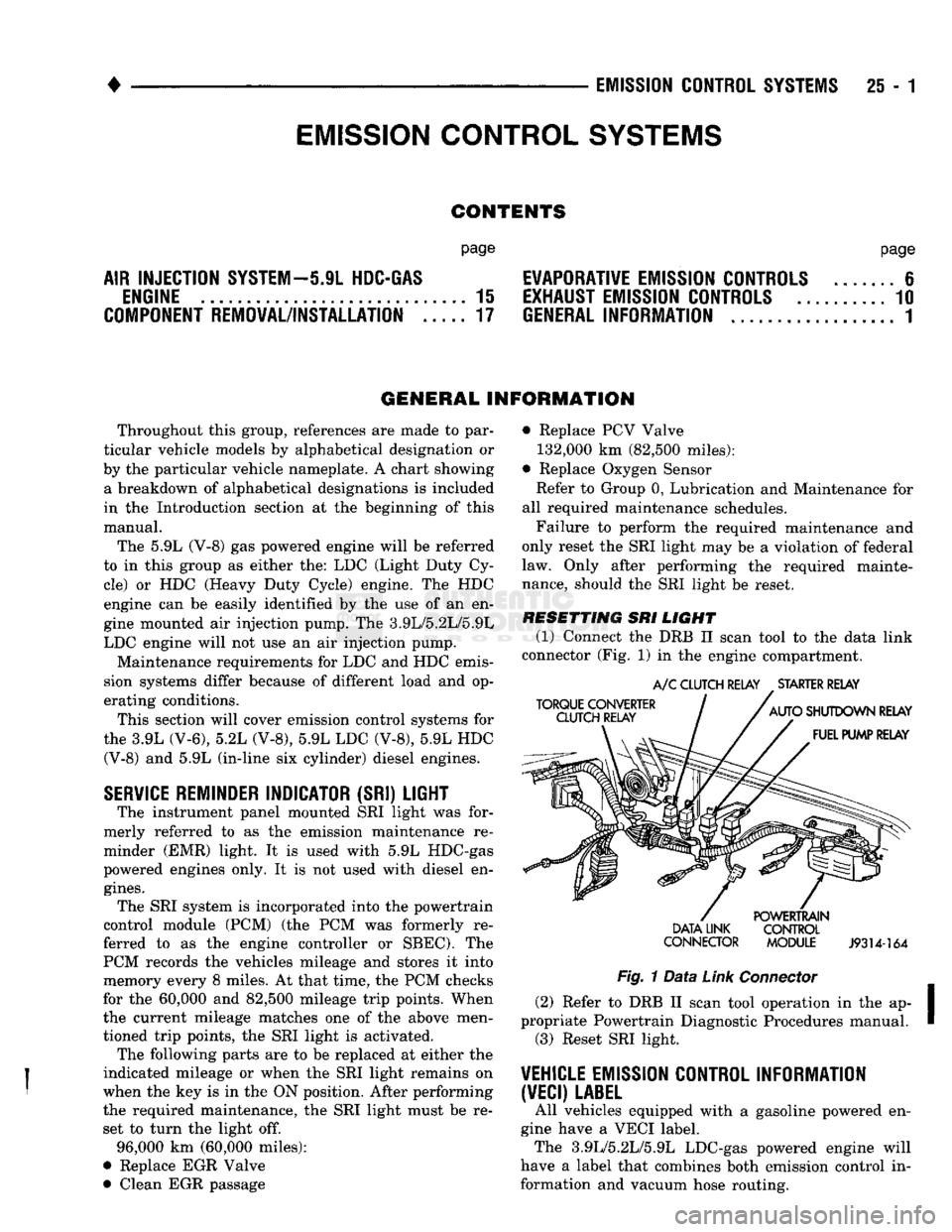
(1) Connect
the
DRB
II
scan tool
to
the
data link
connector (Fig.
1)
in
the engine compartment.
TORQUE CONVERTER
CLUTCH RELAY
A/C
CLUTCH RELAY
.
STARTER RELAY
AUTO
SHUTDOWN RELAY FUEL PUMP RELAY DATA LINK
CONNECTOR POWERTRAIN
CONTROL
MODULE
J9314-164
Fig.
1
Data
Link
Connector
(2) Refer
to
DRB
II
scan tool operation
in
the ap
propriate Powertrain Diagnostic Procedures manual. (3) Reset SRI light.
VEHICLE
EMISSION CONTROL INFORMATION
(VECI)
LABEL
All vehicles equipped with
a
gasoline powered
en
gine have
a
VECI label. The 3.9L/5.2L/5.9L LDC-gas powered engine will
have
a
label that combines both emission control
in
formation and vacuum hose routing.
EMISSION CONTROL
SYSTEMS
Page 1483 of 1502
25
- 6
EMISSION CONTROL
SYSTEMS
•
EWAPORATIWE EMISSION CONTROLS
INDEX
page
Crankcase
Breather/Filter—Gas Powered
Engines
. . . 9
EVAP
(Evaporation)
Control
System
. 6
EVAP
Canister
. . 6
page
Evap
Canister
Purge
Solenoid
6
Fuel Tank
Filler
Tube
Cap . 7
Positive
Crankcase
Ventilation
(PCV)
System
.... 7
Pressure
Relief/Rollover Valve
6
EVAP (EVAPORATION) CONTROL SYSTEM GENERAL
INFORMATION
The function
of the
EVAP control system
is to
pre
vent
the
emissions
of
gasoline vapors from
the
fuel
tank into
the
atmosphere. When fuel evaporates
in
the fuel tank,
the
vapors pass through vent hoses
or
tubes
to a
carbon filled EVAP canister. They
are
temporarily held
in the
canister until they
can be
drawn into
the
intake manifold when
the
engine
is
running.
The vapors
are
drawn into
the
engine
at
idle
as
well
as off
idle. This system
is
called
a
Bi-level Purge
System where there
is a
dual source
of
vacuum
to re
move fuel vapor from
the
EVAP canister. The EVAP canister
is a
feature
on all
models
for
the storage
of
fuel vapors from
the
fuel tank.
The hoses used
in
this system
are
specially
manufactured.
If
replacement becomes neces sary,
it is
important
to use
only fuel resistant
hose.
PRESSURE
RELIEF/ROLLOVER VALVE
These vehicles
are
equipped with
a
combination
pressure relief
and
rollover valve. This dual function valve will relieve fuel tank pressure
and
also prevent
fuel flow through
the
fuel tank vent hoses
in the
event
of an
accidental vehicle rollover. The valve incorporates
a
pressure relief mechanism
that releases fuel tank pressure when
the
pressure increases above
the
calibrated sealing value. Refer
to
the Fuel Tank section
of
Group
14,
Fuel Systems
for
removal
and
installation procedures.
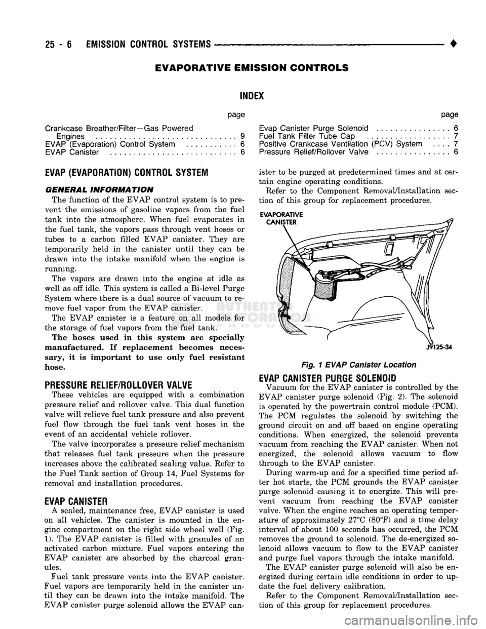
EVAP CANISTER
A sealed, maintenance free, EVAP canister
is
used
on
all
vehicles.
The
canister
is
mounted
in the en
gine compartment
on the
right side wheel well
(Fig.
1).
The
EVAP canister
is
filled with granules
of an
activated carbon mixture. Fuel vapors entering
the
EVAP canister
are
absorbed
by the
charcoal gran
ules.
Fuel tank pressure vents into
the
EVAP canister.
Fuel vapors
are
temporarily held
in the
canister
un
til they
can be
drawn into
the
intake manifold.
The
EVAP canister purge solenoid allows
the
EVAP can ister
to be
purged
at
predetermined times
and at
cer
tain engine operating conditions.
Refer
to the
Component Removal/Installation sec
tion
of
this group
for
replacement procedures.
EVAPORATIVE
Fig.
1
EVAP
Canister Location
EVAP CANISTER PURGE SOLENOID
Vacuum
for the
EVAP canister
is
controlled
by the
EVAP canister purge solenoid
(Fig. 2). The
solenoid
is operated
by the
powertrain control module (PCM).
The
PCM
regulates
the
solenoid
by
switching
the
ground circuit
on and off
based
on
engine operating conditions. When energized,
the
solenoid prevents
vacuum from reaching
the
EVAP canister. When
not
energized,
the
solenoid allows vacuum
to
flow
through
to the
EVAP canister. During warm-up
and for a
specified time period
af
ter
hot
starts,
the PCM
grounds
the
EVAP canister purge solenoid causing
it to
energize. This will pre
vent vacuum from reaching
the
EVAP canister
valve. When
the
engine reaches
an
operating temper ature
of
approximately 27°C (80°F)
and a
time delay
interval
of
about
100
seconds
has
occurred,
the PCM
removes
the
ground
to
solenoid.
The
de-energized
so
lenoid allows vacuum
to
flow
to the
EVAP canister and purge fuel vapors through
the
intake manifold. The EVAP canister purge solenoid will also
be en
ergized during certain idle conditions
in
order
to up
date
the
fuel delivery calibration. Refer
to the
Component Removal/Installation sec
tion
of
this group
for
replacement procedures.
Page 1486 of 1502
•
EMISSION
CONTROL
SYSTEMS
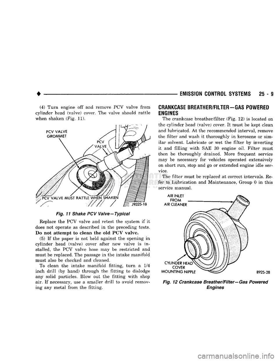
25 - 9 (4) Turn engine off and remove PCV valve from
cylinder head (valve) cover. The valve should rattle
when shaken (Fig. 11).
Fig. 11
Shake
PCV Valve-Typical
Replace the PCV valve and retest the system if it
does not operate as described in the preceding tests.
Do not attempt to clean the old PCV valve.
(5) If the paper is not held against the opening in
cylinder head (valve) cover after new valve is in stalled, the PCV valve hose may be restricted and
must be replaced. The passage in the intake manifold
must also be checked and cleaned. To clean the intake manifold fitting, turn a 1/4
inch drill (by hand) through the fitting to dislodge
any solid particles. Blow out the fitting with shop air. If necessary, use a smaller drill to avoid remov
ing any metal from the fitting.
CRANKCASE
BREATHER/FILTER-GAS POWERED
ENGINES
The crankcase breather/filter (Fig. 12) is located on
the cylinder head (valve) cover. It must be kept clean and lubricated. At the recommended interval, remove
the filter and wash it thoroughly in kerosene or sim ilar solvent. Lubricate or wet the filter by inverting
it and filling with SAE 30 engine oil. Filter must
then be thoroughly drained. More frequent service
may be necessary for vehicles operated extensively on short run, stop and go or extended engine idle ser
vice.
The filter must be replaced at correct intervals. Re
fer to Lubrication and Maintenance, Group 0 in this service manual. 8925-28
Fig. 12 Crankcase Breather/Filter—Gas Powered
Engines
Page 1501 of 1502
CLUSTER
AND
GAUGE SERVICE PROCEDURES
. . . 8E-12
CLUSTER
AND
GAUGE TEST PROCEDURES
8E-5
GENERAL INFORMATION
8E-1
MESSAGE
CENTER-DIESEL ENGINE
8E-4
MESSAGE
CENTER-GAS ENGINE
8E-3
SWITCH
AND
PANEL COMPONENT SERVICE
8E-16
INTRODUCTION
lntro.-1
DESIGNATIONS, LABELS/PLATES/DECALS, CODES AND DIMENSIONS/WEIGHTS
Intro.-1
MEASUREMENT
AND
TORQUE SPECIFICATIONS
lntro.-11
LAMPS
8L-1
BULB APPLICATION
8L-11
EXTERIOR LAMPS
8L-1
EXTERIOR LAMPS SERVICE PROCEDURES
8L-3
INTERIOR LAMPS
8L-10
LUBRICATION
AND
MAINTENANCE
0-1
CHASSIS
AND
BODY
0-28
DRIVETRAIN
0-22
ENGINE MAINTENANCE
0-14
GENERAL INFORMATION
0-1
POWER DOOR LOCKS
8P-1
SERVICE
PROCEDURES
8P-2
TEST PROCEDURES
8P-1
POWER MIRRORS
8T-1
SERVICE
PROCEDURES
8T-2
TEST PROCEDURES
8T-1
POWER WINDOWS
8S-1
SERVICE
PROCEDURES
8S-3
TEST PROCEDURES
8S-1
PROPELLER SHAFTS
16-1
GENERAL INFORMATION
16-1
PROPELLER SHAFT REPLACEMENT
16-8
SERVICE
DIAGNOSIS/PROCEDURES
16-3
TORQUE SPECIFICATIONS
16-15
UNIVERSAL
JOINT
REPLACEMENT
16-10
REAR
SUSPENSION
AND
AXLE
3-1
8
3/8 and 9 1/4
AXLE
3-11
GENERAL INFORMATION
3-1
MODEL
60 and 70
AXLES
3-29
POWER-LOK DIFFERENTIAL
3-55
REAR
SUSPENSION—2WD
and 4WD
VEHICLES
.... 3-3
SERVICE
DIAGNOSIS
3-6
SPECIFICATIONS
3-27
SURE-GRIP
DIFFERENTIAL SERVICE
3-28
TORQUE SPECIFICATIONS
3-59
TRAC-LOK DIFFERENTIAL
3-51
REAR
WINDOW DEFOGGER
8N-1
REPAIR PROCEDURES (GRID LINES, TERMINALS,
AND PIGTAILS)
8N-3
SERVICE
PROCEDURES
8N-4
TEST PROCEDURES
8N-1
STEERING
19-1
GENERAL INFORMATION
19-1
POWER STEERING PUMP
19-11
POWER STEERING SYSTEM DIAGNOSIS
19-2
RECIRCULATING BALL POWER STEERING GEAR
. . 19-20
STEERING COLUMN
19-35
STEERING LINKAGE
19-17
TORQUE SPECIFICATIONS
19-40
TRANSMISSION
AND
TRANSFER CASE
21-1
AUTOMATIC TRANSMISSION DIAGNOSIS
AND
TESTING
21-85
AUTOMATIC TRANSMISSION REMOVAL
AND
INSTALLATION
21-142
AUTOMATIC TRANSMISSION—32RH/36RH/37RH/
42RH/46RH
21-73
G360
MANUAL TRANSMISSION
21-46
G360
TRANSMISSION OVERHAUL
21-53
GENERAL INFORMATION-32RH/36RH/37RH
21-73
GENERAL INFORMATION—42RH/46RH
. . . 21-78
IN-VEHICLE SERVICE—32RH/36RH/37RH/ 42RH/46RH
21-130
NP205
TRANSFER CASE
21-342
NP241
TRANSFER CASE
21-350
NV4500
MANUAL TRANSMISSION
21-1
NV4500
TRANSMISSION OVERHAUL
21-6
OVERDRIVE
UNIT
OVERHAUL—42RH/46RH
21-324
TRANSMISSION OVERHAUL—32RH
21-152
TRANSMISSION OVERHAUL—36RH/37RH
21-192
TRANSMISSION OVERHAUL—42RH
21-233
TRANSMISSION OVERHAUL—46RH
21-278
TRANSMISSION/TRANSFER CASE SPECIFICATIONS
21-364
TURN SIGNALS
AND
HAZARD WARNING FLASHER
. . . 8J-1
GENERAL INFORMATION
8J-1
MULTIFUNCTION SWITCH SERVICE PROCEDURES.
. 8J-3
MULTIFUNCTION SWITCH TESTING PROCEDURES.
. 8J-2
VEHICLE
SPEED
CONTROL SYSTEM
8H-1
SERVICE
PROCEDURES
8H-11
TEST PROCEDURES
8H-7
WHEELS
AND
TIRES
22-1
TIRES
22-1
TORQUE SPECIFICATIONS
22-13
VEHICLE VIBRATION
22-11
WHEELS
22-6
WINDSHIELD WIPER
AND
WASHER
SYSTEMS
8K-1
INTERMITTENT WINDSHIELD WIPER FUNCTION
AND
SWITCH TESTING PROCEDURES
8K-6
TWO
SPEED
WINDSHIELD WIPER MOTOR
AND
SWITCH TESTING PROCEDURES
8K-1
WINDSHIELD WASHERS
8K-10
WINDSHIELD WIPER SYSTEM SERVICE
PROCEDURES
8K-7
WIRING DIAGRAMS
8W-1
COMPONENT IDENTIFICATION
8W-9
GENERAL INFORMATION
8W-1
SPLICE
LOCATIONS
8W-29
WIRING DIAGRAMS AD-BODY
8W-37