maintenance DODGE TRUCK 1993 Service Workshop Manual
[x] Cancel search | Manufacturer: DODGE, Model Year: 1993, Model line: TRUCK, Model: DODGE TRUCK 1993Pages: 1502, PDF Size: 80.97 MB
Page 612 of 1502
•
ENGINES
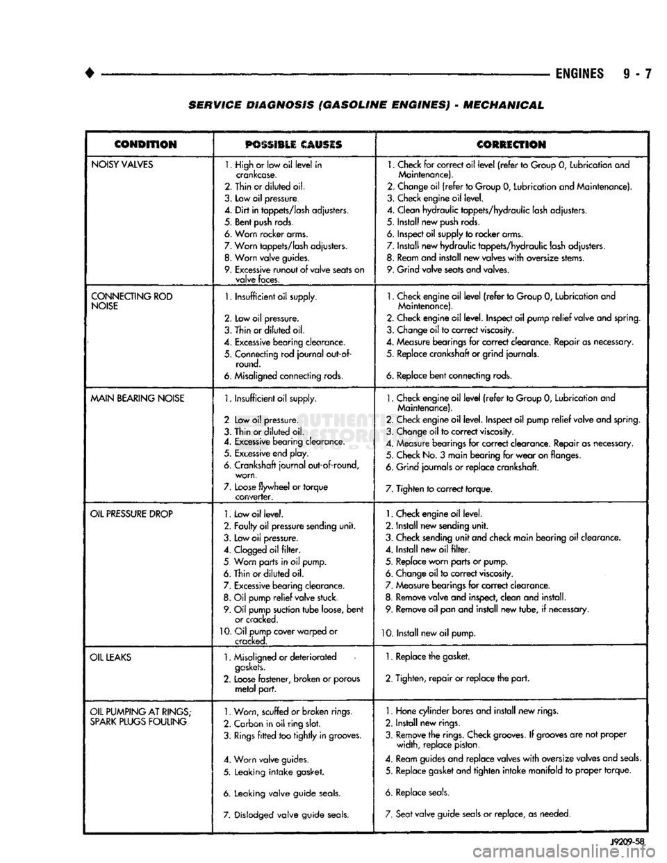
9 - 7 SERVICE DIAGNOSIS (GASOLINE ENGINES) - MECHANICAL
CONDITION
PSSSI1LI
CAUSIS
CORRECTION
NOISY
VALVES
1. High
or
low oil
level
in
crankcase.
2. Thin or
diluted
oil.
3.
Low
oil
pressure.
4.
Dirt
in
tappets/lash
adjusters.
5. Bent
push
rods.
6. Worn rocker arms.
7.
Worn
tappets/lash
adjusters.
8.
Worn
valve
guides.
9.
Excessive
runout
of
valve
seats
on
valve
faces.
1.
Check
for
correct oil
level
(refer
to
Group
0,
Lubrication and
Maintenance).
2. Change oil
(refer
to Group
0,
Lubrication and Maintenance).
3. Check engine oil level.
4. Clean hydraulic tappets/hydraulic lash adjusters.
5. Install new
push
rods.
6. Inspect oil supply to rocker arms.
7. Install new hydraulic tappets/hydraulic lash adjusters. 8. Ream and install new valves
with
oversize stems.
9. Grind valve seats and valves.
CONNECTING
ROD
NOISE
1.
Insufficient oil supply.
2.
Low oil
pressure.
3.
Thin
or
diluted
oil.
4.
Excessive
bearing
clearance.
5. Connecting rod
journal
out-of- round.
6. Misaligned connecting rods.
1.
Check engine oil
level
(refer
to Group
0,
Lubrication and
Maintenance).
2. Check engine oil level. Inspect oil pump
relief
valve and spring.
3. Change oil to correct
viscosity.
4. Measure bearings for correct clearance. Repair as necessary, 5. Replace crankshaft or grind journals.
6.
Replace
bent
connecting rods.
MAIN
BEARING
NOISE
1.
Insufficient oil supply.
2 Low
oil
pressure.
3. Thin or
diluted
oil.
4.
Excessive
bearing clearance. 5.
Excessive
end play.
6. Crankshaft
journal
out-of-round, worn,
7.
Loose
flywheel
or
torque
converter.
1.
Check engine oil
level
(refer
to Group
0,
Lubrication and
Maintenance).
2. Check engine oil level. Inspect oil pump
relief
valve and spring.
3. Change oil to correct
viscosity.
4. Measure bearings for correct clearance. Repair as necessary. 5. Check No.
3
main bearing for
wear
on flanges.
6. Grind journals
or
replace crankshaft.
7. Tighten to correct torque.
OIL
PRESSURE
DROP
1.
Low oil level.
2. Faulty oil pressure sending
unit.
3. Low
oil
pressure.
4.
Clogged
oil
filter.
5 Worn parts in
oil
pump.
6. Thin or
diluted
oil.
7.
Excessive
bearing clearance. 8.
Oil
pump
relief
valve stuck.
9. Oil pump suction
tube
loose,
bent
or cracked.
10.
Oil pump cover warped
or
cracked.
1.
Check engine oil level.
2. Install new sending
unit.
3. Check sending
unit
and check main bearing oil clearance.
4. Install new oil
filter.
5. Replace worn parts or pump. 6. Change oil to correct
viscosity.
7. Measure bearings for correct clearance.
8. Remove valve and inspect, clean and install. 9. Remove oil pan and install new tube,
if
necessary.
10. Install new oil pump.
OIL
LEAKS
1.
Misaligned or
deteriorated
gaskets.
2.
Loose
fastener, broken
or
porous
metal
part.
1. Replace the gasket.
2. Tighten,
repair
or replace the
part.
OIL
PUMPING
AT
RINGS;
SPARK
PLUGS
FOULING
1.
Worn, scuffed
or broken
rings.
2. Carbon in oil ring
slot.
3.
Rings
fitted
too
tightly
in grooves.
4. Worn valve guides.
5. Leaking
intake
gasket.
6. Leaking valve guide
seals.
7. Dislodged valve guide
seals.
1.
Hone cylinder bores and install new rings.
2. Install new rings.
3. Remove the rings. Check
grooves.
If
grooves
are not proper width, replace piston.
4. Ream guides and replace valves
with
oversize valves and
seals.
5. Replace gasket and tighten
intake
manifold
to
proper torque.
6. Replace
seals.
7. Seat
valve guide
seals
or
replace, as needed.
J9209-58
Page 620 of 1502
•
• —
ENGINES
9 - 15
CONDITION
POSSIBLE CAUSES
CORRECTION
LUBRICATING
OIL
PRESSURE
TOO
HIGH
Pressure
switch/gauge
not
operating
properly.
Verify
the
pressure
switch
is
functioning
correctly.
If not,
replace
switch/gauge.
Engine
running
too
cold.
Refer
to
Coolant
Temperature
Below
Normal
(Engine
Diagnosis-
Performance)
Oil
viscosity
too thick. Make
sure
the
correct
oil Is
being
used.
Refer
to
Group
O,
Lubrication
and
Maintenance.
Oil
pressure
regulator
valve
stuck
closed
or
binding.
Check
and replace valve, and/or oil cooler cover.
LUBRICATING
OIL
LOSS
External
leaks.
Visually
inspect for oil
leaks.
Repair as required.
Crankcase
being
overfilled. Verify that the correct dipstick is being
used.
incorrect
oil specification or
viscosity.
(a) Make sure the correct oil is being
used.
(b)
Look
for reduced
viscosity
from dilution with fuel.
(c) Review/reduce the oil
change
intervals.
Oil
cooler
leak.
Check
and replace the oil cooler.
High
blow-by
forcing oil out
the breather.
Check
the breather tube area for
signs
of oil
loss.
Perform the
required repairs.
Turbocharger
leaking
oil to the
air intake.
Inspect
the air
ducts
for evidence of oil transfer.
Repair
as required.
Worn
valve
seals.
Inspect
and replace the valve
seals.
Piston
rings
not
sealing
(oil
being
consumed
by the
engine).
Perform
blow-by check. Repair as required.
COMPRESSION
KNOCKS
Air in the
fuel
system.
Poor
quality
fuel.
Bleed
the fuel
system
(refer
to
Group
14, Fuel
System).
Verify by operating from a temporary tank with
good
fuel. Clean
and
flush the fuel
supply
tanks.
Replace fuel/water separator
filter.
Engine
overloaded. Verify that engine load rating is not being exceeded.
Incorrect injection
pump
timing.
Check
and time injection pump
(refer
to
Group
14, Fuel
System).
Improperly
operating
injectors.
Check
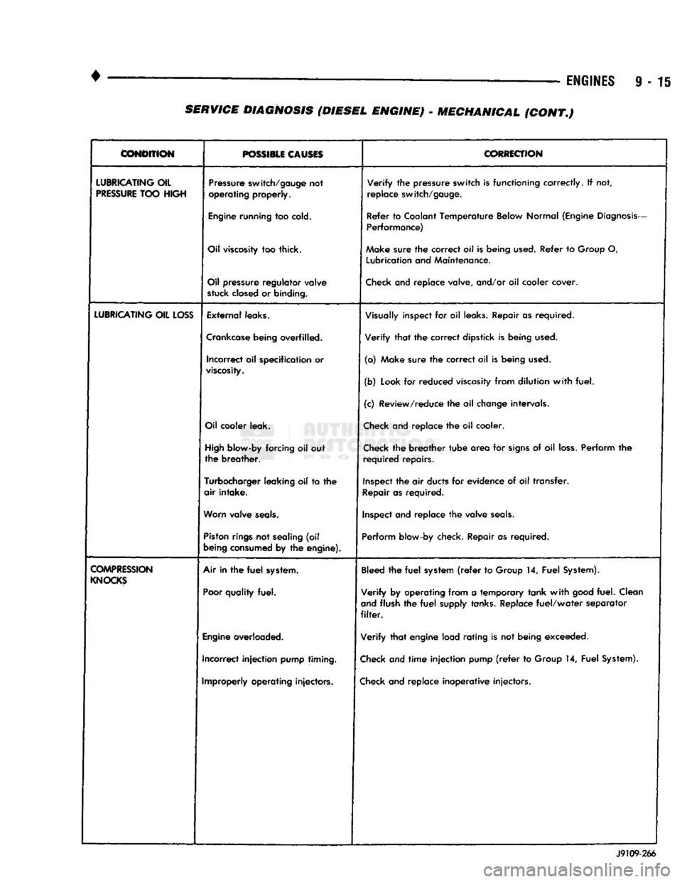
and replace inoperative injectors. J9109-266 SERVICE DIAGNOSIS (DIESEL ENGINE) - MECHANICAL (CONT.)
Page 717 of 1502
9
- 112 5.9L
(DIESEL)
ENGINE
• (5) Position the engine in the chassis and install
the through bolt. Tighten the through bolt nut to 41
N-m (30 ft. lbs.) torque. (6) Make sure the lifting brackets are mounted
with the eye down. (7) Remove the covers or tape covering the engine
openings. (8) Connect the fuel lines to the lift pump and fuel
return.
(9) Connect all electrical connections.
(10) Connect the power steering lines.
(11) Raise and support the vehicle on a hoist.
(12) AUTOMATIC TRANSMISSION:
CAUTION:
If new
flex
plate is installed, remove
flashing
from the engine
back
plate at the 5 and 7
o'clock
positions.
(a) Rotate converter until alignment mark on the
converter is aligned with mark on drive plate.
Off
set holes in plate are next to 1/8 inch hole in inner
circle of drive plate.
(b) Install bell housing bolts. Tighten the bolts to
41 N-m (30 ft. lbs.) torque. (c) With the torque converter plate aligned to the
torque converter, install and tighten the bolts to 31 N-m (270 in. lbs.) torque. (d) Install the converter housing access plate.
(e) Remove the transmission support.
(13) MANUAL TRANSMISSION:
Refer to Group 21, Transmissions for the G360
Manual Transmission Installation procedure. (14) Connect the ground cable and tighten the nut
to 22 N-m (16 ft. lbs.) torque. Connect the solenoid cable and tighten the nut to 5 N-m (44 in. lbs.)
torque.
(15) Connect the transmission cooler lines.
(16) Install the exhaust pipe to the exhaust sys
tem.
(17) Lower the vehicle.
(18) Install the A/C compressor and tighten the
bolts to 47 N-m (35 ft. lbs.) torque. If removed, con nect the clutch electrical wire.
(19) Install the generator. Tighten the upper
mounting bolts to 24 N-m (18 ft. lbs.) torque. Now
tighten the lower mounting bolts to 43 N-m (32 ft. lbs.) torque. Connect all wires.
(20) Install the radiator, fan/fan clutch assembly
and fan shroud (refer to Group 7, Cooling Systems
for the proper procedures). Connect the radiator
hoses.
(21) Position the intercooler inlet duct to the tur
bocharger and the intercooler. With the clamps in po sition, tighten the clamp nut to 8 N-m (72 in. lbs.)
torque. (22) Position the intercooler outlet duct to the air
inlet housing and the intercooler. With the clamps in
position, tighten the clamp nut to 8 N-m (72 in. lbs.)
torque.
(23) Connect the air intake tube to the turbo
charger inlet flange and the air cleaner housing.
Tighten the clamps to 8 N-m (72 in. lbs.) torque. (24) Install the exhaust pipe to the turbocharger.
Tighten the steady rest clamp to 8 N-m (72 in. lbs.) torque.
(25) Make sure the air intake and exhaust pipe
connections are tight and free of leaks.
(26) Fill the engine with the required amount of
clean engine lubricating oil (refer to Group 0, Lubri cation and Maintenance).
(27) Fill the cooling system with a mixture of 50%
water and 50% ethylene-glycol base antifreeze (refer Group 7, Cooling System for the proper procedure).
(28) Install the battery and connect the battery ca
bles.
(29) Check the oil level after the engine has run
for 2 or 3 minutes. Oil held in the oil filter and oil passages will cause the oil level in the pan to be lower.
(30) Operate the engine at idle for 5 to 10 minutes
and check for leaks and loose parts.
ROCKER LEVERS
/
POSH
RODS
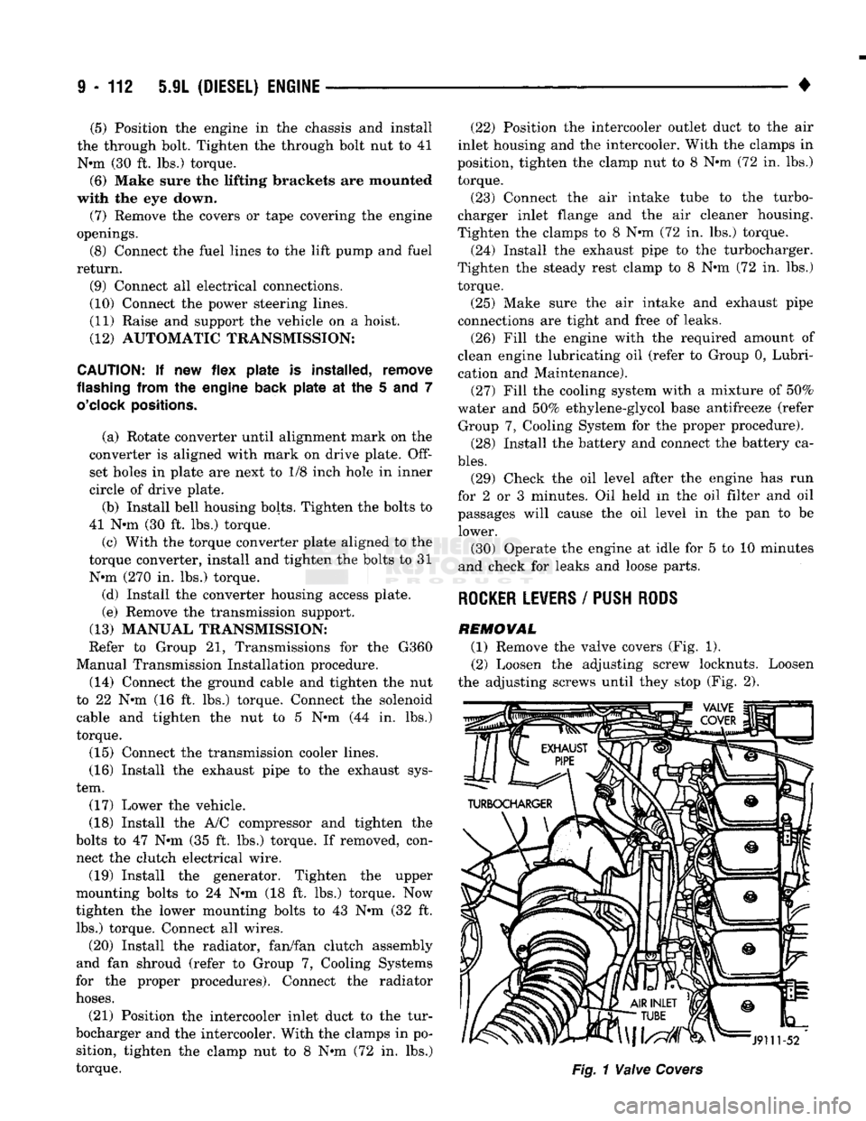
REMOVAL (1) Remove the valve covers (Fig. 1). (2) Loosen the adjusting screw locknuts. Loosen
the adjusting screws until they stop (Fig. 2).
Page 721 of 1502
9
- 116 5.9L
(DIESEL) ENGINE
•
CYLINDER HEAD
Fig. 11 Cylinder Head/Gasket Alignment J9109-36
Fig. 12 Cylinder Head Tightening Sequence
(7) Be sure to lubricate the push rod sockets with
clean engine oil.
(8) Install the rocker lever pedestal bolts and
tighten to 24 N*m (18 ft. lbs.) torque. (9) Adjust the valve clearance.
(10) Install the valve covers. Tighten the bolts to
24 N*m (18 ft. lbs.) torque.
(11) Install the injector nozzles and fuel lines (refer
to Group 14, Fuel System).
(12) Install the fuel filter (refer to Group 14, Fuel
System for the proper procedures). (13) Install the exhaust manifold (refer to Group
11,
Exhaust System and Intake Manifold).
(14) Install the turbocharger.
(15) Connect the radiator and heater hoses. (16) Fill the engine with new coolant or the clean
drained coolant (refer to Group 7, Cooling System for
the proper procedure). (17) Fill the engine with clean lubricating oil (re
fer to Group 0, Lubrication and Maintenance).
VALVES
AND VALVE
SPRINGS
REMOWAL
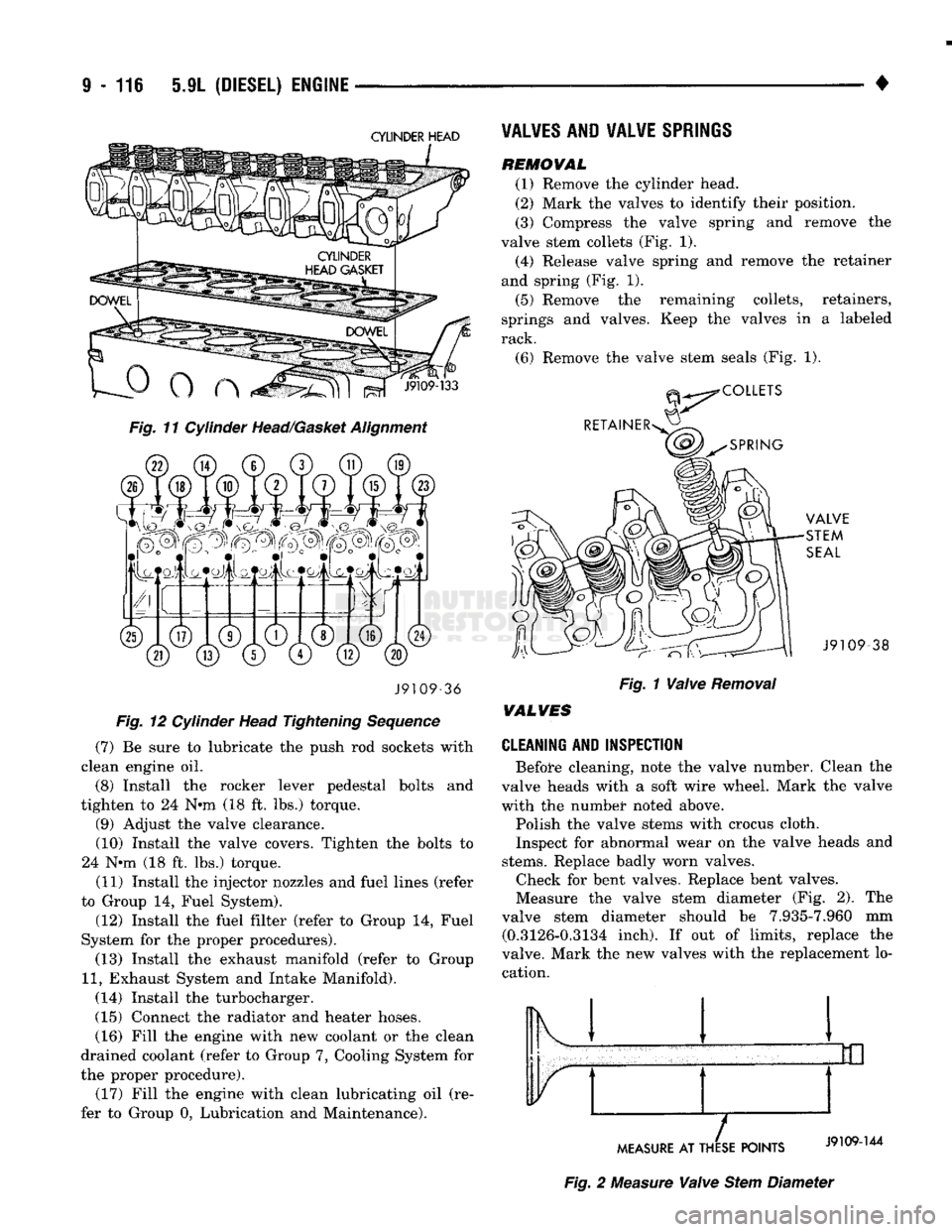
(1) Remove the cylinder head.
(2) Mark the valves to identify their position.
(3) Compress the valve spring and remove the
valve stem collets (Fig. 1). (4) Release valve spring and remove the retainer
and spring (Fig. 1).
(5) Remove the remaining collets, retainers,
springs and valves. Keep the valves in a labeled
rack.
(6) Remove the valve stem seals (Fig. 1). -38
Fig. 1 Valve Removal
WALVES
CLEANING AND INSPECTION
Before cleaning, note the valve number. Clean the
valve heads with a soft wire wheel. Mark the valve
with the numbet* noted above.
Polish the valve stems with crocus cloth.
Inspect for abnormal wear on the valve heads and
stems.
Replace badly worn valves. Check for bent valves. Replace bent valves.
Measure the valve stem diameter (Fig. 2). The
valve stem diameter should be 7.935-7.960 mm (0.3126-0.3134 inch). If out of limits, replace the
valve. Mark the new valves with the replacement lo cation. Ik 1
MEASURE
AT THESE POINTS
Fig. 2 Measure Valve Stem Diameter
Page 749 of 1502
9 - 146 5.9L (DIESEL) ENGINE
•
DIAL
INDICATOR
CYLINDER BLOCK
GASKET
J9109-97
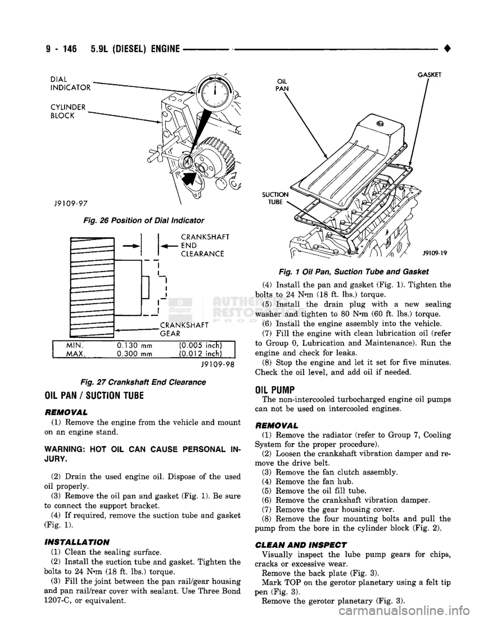
Fig.
26 Position of Dial Indicator CRANKSHAFT
END
CLEARANCE
CRANKSHAFT
GEAR
MIN.
MAX.
0.130
mm
0.300 mm (0M5 inch)
(0.012 inch)
J9109-98
Fig.
27 Crankshaft End Clearance
OIL PAN / SUCTION TU1E
REMOVAL (1) Remove the engine from the vehicle and mount
on an engine stand.
WARNING:
HOT OIL CAN
CAUSE PERSONAL
IN
JURY.
(2) Drain the used engine oil. Dispose of the used
oil properly. (3) Remove the oil pan and gasket (Fig. 1). Be sure
to connect the support bracket.
(4) If required, remove the suction tube and gasket
(Fig. 1).
INSTALLATION (1) Clean the sealing surface.
(2) Install the suction tube and gasket. Tighten the
bolts to 24 Nin (18 ft. lbs.) torque.
(3) Fill the joint between the pan rail/gear housing
and pan rail/rear cover with sealant. Use Three Bond 1207-C, or equivalent.
SUCTION
TUBE
J9109-19
Fig.
1 Oil Pan,
Suction
Tube and
Gasket
(4) Install the pan and gasket (Fig. 1). Tighten the
bolts to 24 N-m (18 ft. lbs.) torque.
(5) Install the drain plug with
a
new sealing
washer and tighten to 80 Nnn (60 ft. lbs.) torque.
(6) Install the engine assembly into the vehicle.
(7) Fill the engine with clean lubrication oil (refer
to Group 0, Lubrication and Maintenance). Run the engine and check for leaks.
(8) Stop the engine and let it set for five minutes.
Check the oil level, and add oil if needed.
OIL
PUMP
The non-intercooled turbocharged engine oil pumps
can not be used on intercooled engines.
REMOVAL (1) Remove the radiator (refer to Group 7, Cooling
System for the proper procedure). (2) Loosen the crankshaft vibration damper and re
move the drive belt.
(3) Remove the fan clutch assembly. (4) Remove the fan hub.
(5) Remove the oil fill tube.
(6) Remove the crankshaft vibration damper.
(7) Remove the gear housing cover.
(8) Remove the four mounting bolts and pull the
pump from the bore in the cylinder block (Fig. 2).
CLEAN AND INSPECT Visually inspect the lube pump gears for chips,
cracks or excessive wear.
Remove the back plate (Fig. 3).
Mark TOP on the gerotor planetary using a felt tip
pen (Fig. 3). Remove the gerotor planetary (Fig. 3).
Page 751 of 1502
9
- 148 5.9L
(DIESEL) ENGINE
• Make sure the idler gear pin is installed in the lo
cating bore in the cylinder block. (2) Install the pump. Tighten the oil pump mount
ing bolts in two steps and in the sequence shown (Fig. 2).
• Step
1—Tighten
to 5 N«m (44 in. lbs.) torque.
• Step 2-Tighten to 24 N*m (18 ft. lbs.) torque. (3) The back plate on the pump seats against the
bottom of the bore in the cylinder block. When the
pump is correctly installed, the flange on the pump will not touch the cylinder block.
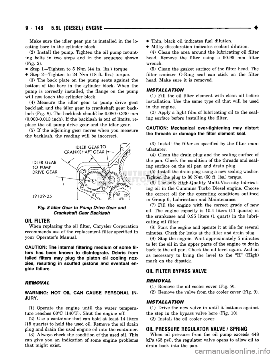
(4) Measure the idler gear to pump drive gear
backlash and the idler gear to crankshaft gear back lash (Fig. 8). The backlash should be 0.080-0.330 mm (0.003-0.013 inch). If the backlash is out of limits, re
place the oil pump drive gear and the idler gear.
(5) If the adjoining gear moves when you measure
the backlash, the reading will be incorrect.
Fig.
8
idler
Gear to
Pump
Drive Gear and Crankshaft Gear
Backlash
OIL FILTER
When replacing the oil filter, Chrysler Corporation
recommends use of the replacement filter specified in
your Operator's Manual.
CAUTION:
The
internal filtering medium
of
some
fil
ters
has
been known
to
disintegrate. Debris from
failed filters
may
plug
the
piston
oil
cooling noz
zles,
resulting
in
scuffed pistons
and
eventual
en
gine
failure.
REMOVAL
WARNING:
HOT OIL CAN
CAUSE PERSONAL
IN
JURY.
(1) Operate the engine until the water tempera
ture reaches 60°C (140°F). Shut the engine off.
(2) Use a container that can hold at least 14 liters
(15 quarts) to hold the used oil. Remove the oil drain
plug and drain the used engine oil into the container.
(3) Always check the condition of the used oil. This
can give you an indication of some engine problems
that might exist. • Thin, black oil indicates fuel dilution.
• Milky discoloration indicates coolant dilution.
(4) Clean the area around the lubricating oil filter
head. Remove the filter using a 90-95 mm filter
wrench.
(5) Clean the gasket surface of the filter head. The
filter canister O-Ring seal can stick on the filter
head. Make sure it is removed.
INSTALLATION (1) Fill the oil filter element with clean oil before
installation. Use the same type oil that will be used
in the engine.
(2) Apply a light film of lubricating oil to the seal
ing surface before installing the filter.
CAUTION:
Mechanical over-tightening
may
distort
the threads
or
damage
the filter
element seal.
(3) Install the filter as specified by the filter man
ufacturer. (4) Clean the drain plug and the sealing surface of
the pan. Check the condition of the threads and seal ing surface on the oil pan and drain plug.
(5) Install the drain plug using a new sealing washer.
Tighten the plug to 80 N-m (60 ft. lbs.) torque.
(6) Use only High-Quality Multi-Viscosity lubricat
ing oil in the Cummins Turbo Diesel engine. Choose
the correct oil for the operating conditions outlined in Group 0, Lubrication and Maintenance.
(7) Fill the enginfe with the correct grade of new
oil.
The engine capacity is i0.4 liters (11 quarts) in
the crankcase and 0.95 liters (1 quart) in the lubri cating oil filter. (8) Start the engine and operate it at idle for several
minutes. Check for leaks at the filter and drain plug.
(9) Stop the engine. Wait approximately 5 minutes
to let the oil in the upper parts of the engine to drain
back to the oil pan. Check the oil level again. Add oil as necessary to bring the level to the "H" (High)
mark on the dipstick.
OIL FILTER
BYPASS
VALWE
REMOVAL
(1) Remove the oil cooler cover (Fig. 9). (2) Remove the valve from the cooler cover (Fig. 9).
INSTALLATION (1) Drive the new valve in until it bottoms against
the step in the bypass valve bore (Fig. 10).
(2) Install the oil cooler cover.
OIL PRESSURE REGULATOR VALVE
/
SPRING
When oil pressure from the oil pump exceeds 448
kPa (65 psi), the regulator valve opens to allow oil to
drain back into the pan.
Page 855 of 1502
trol (IAC) stepper motor position to compensate for
increased engine load from the A/C compressor.
By switching the ground path for the relay on and
off, the PCM is able to cycle the A/C compressor
clutch. This is based on changes in engine operating
conditions. If, during A/C operation, the PCM senses
low idle speeds or a wide open throttle condition, it
will de-energize the relay. This prevents A/C clutch engagement. The relay will remain de-energized un
til the idle speed increases or the wide open throttle condition exceeds 15 seconds or no longer exists. The
PCM will also de-energize the relay if coolant tem
perature exceeds 125°C (257°F).
IDLE
AIR
CONTROL
(IAC)
MOTOR-PCM OUTPUT
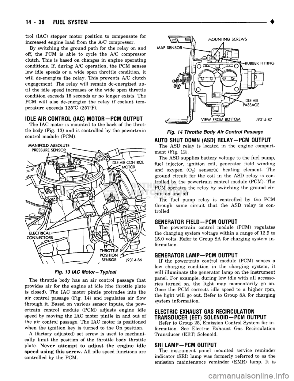
The IAC motor is mounted to the back of the throt
tle body (Fig. 13) and is controlled by the powertrain control module (PCM).
AAANIFOLD ABSOLUTE
PRESSURE
SENSOR
MOUNTING
SCREWS
MAP SENSOR
THROTTLE
POSITION
SENSOR
J9314-86
Fig.
13 IAC Motor—Typical The throttle body has an air control passage that
provides air for the engine at idle (the throttle plate is closed). The IAC motor pintle protrudes into the
air control passage (Fig. 14) and regulates air flow
through it. Based on various sensor inputs, the pow
ertrain control module (PCM) adjusts engine idle speed by moving the IAC motor pintle in and out of
the air control passage. The IAC motor is positioned
when the ignition key is turned to the On position.
A (factory adjusted) set screw is used to mechani
cally limit the position of the throttle body throttle
plate. Never attempt to adjust the engine idle speed using this screw. All idle speed functions are
controlled by the PCM.
RUBBER
FITTING
J9314-87
Fig.
14
Throttle
Body
Air Control
Passage
AUTO SHUT DOWN (ASD) RELAY—PCM OUTPUT
The ASD relay is located in the engine compart
ment (Fig. 12). The ASD supplies battery voltage to the fuel pump,
fuel injector, ignition coil, generator field winding and oxygen (02) sensor(s) heating element. The
ground circuit for the coil in the ASD relay is con
trolled by the powertrain control module (PCM). The PCM operates the relay by switching the ground cir
cuit on and off. The fuel pump relay is controlled by the PCM
through same circuit that the ASD relay is con trolled.
GENERATOR FIELD-PCM OUTPUT
The powertrain control module (PCM) regulates
the charging system voltage within a range of 12.9 to 15.0 volts. Refer to Group 8A for charging system in
formation.
GENERATOR LAMP-PCM OUTPUT
If the powertrain control module (PCM) senses a
low charging condition in the charging system, it
will illuminate the generator lamp on the instrument
panel. For example, during low idle with all accesso
ries turned on, the light may momentarily go on. Once the PCM corrects idle speed to a higher rpm,
the light will go out. Refer to Group 8A for charging system information.
ELECTRIC
EXHAUST GAS RECIRCULATION
TRANSDUCER
(EET)
S0LEN0ID-PCM OUTPUT
Refer to Group 25, Emission Control System for in
formation. See Electric Exhaust Gas Recirculation
Transducer (EET) Solenoid.
SRI
LAMP-PCM OUTPUT
The instrument panel mounted service reminder
indicator (SRI) lamp was formerly referred to as the
emission maintenance reminder (EMR) lamp. It is
Page 904 of 1502
•
FUEL SYSTEM
14-85 to pass through it, but prevents moisture (water)
from doing so. Moisture collects at the bottom of the
separator filter.
WARNING:
EXTINGUISH
ALL
SMOKING
MATERI
ALS
BEFORE
DRAINING
THE
FUEL/WATER
SEPA
RATOR
FILTER.
There is a drain at the bottom of the separator fil
ter (Fig. 16). Place a drain pan under the drain tube.
With the engine not running, push up on the drain
to remove the water from the separator filter. Hold
the drain open until all water and contaminants
have been removed and clean fuel exits the drain. Dispose of mixture in drain pan according to applica
ble regulations.
Refer to the maintenance schedules in Group 0 in
this manual for the recommended fuel/water separa
tor filter replacement intervals.
KSB
SOLENOID
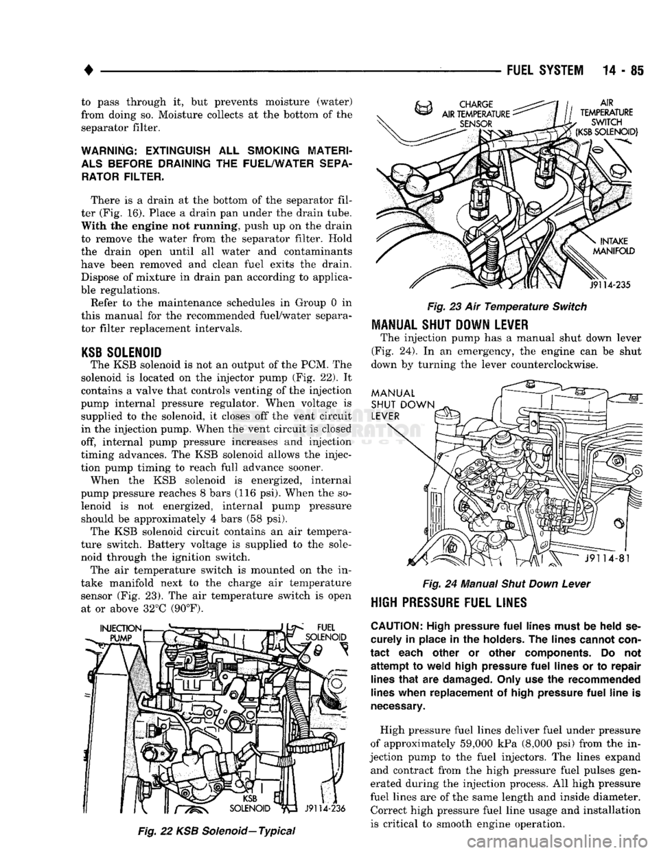
The KSB solenoid is not an output of the PCM. The
solenoid is located on the injector pump (Fig. 22). It
contains a valve that controls venting of the injection
pump internal pressure regulator. When voltage is supplied to the solenoid, it closes off the vent circuit
in the injection pump. When the vent circuit is closed
off, internal pump pressure increases and injection
timing advances. The KSB solenoid allows the injec
tion pump timing to reach full advance sooner. When the KSB solenoid is energized, internal
pump pressure reaches 8 bars (116 psi). When the so lenoid is not energized, internal pump pressure should be approximately 4 bars (58 psi). The KSB solenoid circuit contains an air tempera
ture switch. Battery voltage is supplied to the sole
noid through the ignition switch. The air temperature switch is mounted on the in
take manifold next to the charge air temperature sensor (Fig. 23). The air temperature switch is open at or above 32°C (90°F).
Fig.
22 KSB
Solenoid—
Typical
Fig.
23 Air
Temperature
Switch
MANUAL SHUT DOWN LEVER
The injection pump has a manual shut down lever
(Fig. 24). In an emergency, the engine can be shut
down by turning the lever counterclockwise.
Fig.
24 Manual
Shut
Down
Lever
HIGH
PRESSURE FUEL LINES
CAUTION:
High pressure
fuel
lines must
be
held
se
curely
in
place
in the
holders.
The
lines cannot con
tact
each other
or
other components.
Do not
attempt
to
weld high pressure
fuel
lines
or to
repair lines
that
are
damaged. Only use
the
recommended
lines when replacement
of
high pressure
fuel
line
is
necessary.
High pressure fuel lines deliver fuel under pressure
of approximately 59,000 kPa (8,000 psi) from the in
jection pump to the fuel injectors. The lines expand and contract from the high pressure fuel pulses gen
erated during the injection process. All high pressure
fuel lines are of the same length and inside diameter. Correct high pressure fuel line usage and installation
is critical to smooth engine operation.
Page 912 of 1502
•
FUEL SYSTEM
14-93 There is a drain at the bottom of the separator fil
ter (Fig. 13). Place a drain pan under the drain tube. With the engine not running, hold the drain open
until all water and contaminants have been removed and clean fuel exits the drain. Dispose of mixture in
drain pan according to applicable regulations.
If excess water gathers in separator/filter in a short
time,
the fuel tank must be removed, drained and cleaned.
HIGH
PRESSURE FUEL LINE RESTRICTIONS
High pressure fuel line leaks can cause starting
problems, poor engine performance and engine miss under load. Restricted high pressure lines can cause starting problems, poor engine performance, engine
miss under load and black smoke from exhaust.
WARNING:
USE
EXTREME
CAUTION
WHEN
IN
SPECTING
FOR HIGH
PRESSURE
FUEL
LEAKS.
IN
SPECT
FOR HIGH
PRESSURE
FUEL
LEAKS
WITH
A
SHEET
OF
CARDBOARD.
HIGH
FUEL
INJECTION
PRESSURE
CAN
CAUSE
PERSONAL
INJURY
IF
CONTACT
IS
MADE
WITH
THE
SKIN.
Start the engine. Move the cardboard over the high
pressure fuel lines and check for fuel spray onto the cardboard. If a high pressure line connection is leak
ing, bleed the system and tighten the connection. Re
fer to the 5.9L Diesel Service Procedures section for air bleeding procedures. Replace damaged, restricted
or leaking high pressure fuel lines with the correct replacement line.
CAUTION:
The
high pressure
fuel
lines must
be
clamped securely
in
place
in the
holders.
The
lines cannot contact each other
or
other components.
Do
not
attempt
to
weld high pressure
fuel
lines
or to
repair lines
that
are
damaged. Only
use the
recom
mended lines when replacement
of
high pressure
fuel
line
is
necessary.
KSB
SOLENOID
The KSB solenoid will click when it is energized
and de-energized. If the solenoid does not click when 12 volts is sup
plied to it, replace the solenoid.
MECHANICAL
LIFT
PUMP
An improperly operating lift pump can cause low
engine power. Inspect the fuel supply line to the
pump for restrictions, kinks or leaks. Fuel leaking
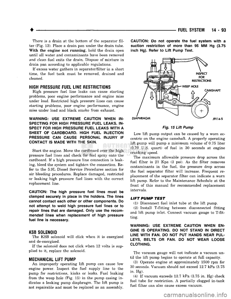
from the weep hole (Fig. 15) in the pump casing in
dicates a leaking pump diaphragm. The lift pump is not repairable and must be replaced as an assembly.
CAUTION:
Do not
operate
the
fuel
system
with
a
suction restriction
of
more than
95 MM Hg (3.75
inch Hg). Refer
to
Lift
Pump Test.
Fig.
15
Lift
Pump
Low lift pump output can be caused by a worn ec
centric on the engine camshaft. A properly operating lift pump will pump a minimum volume of 0.75 liter (0.70 U.S. quart) of fuel in 30 seconds at engine
cranking speed.
The maximum allowable pressure drop across the
fuel filter is 21 Kpa (3 psi). As the filter removes contaminants in the fuel, the pressure drop across
the fuel separator filter will increase. Frequent re
placement of the separator filter can indicate a worn lift pump. Refer to the Maintenance Schedule at the
front of this manual for recommended replacement intervals.
LIFT
PUMP
TEST
(1) Disconnect fuel inlet tube at the lift pump. (2) Install T-fitting between disconnected fitting
and lift pump inlet. Connect vacuum gauge to T-fit
ting.
WARNING:
USE
EXTREME
CAUTION
WHEN
EN
GINE
IS
OPERATING.
DO NOT
STAND
IN
DIRECT
LINE
WITH FAN.
DO NOT PUT
HANDS
NEAR
PUL
LEYS,
BELTS
OR FAN. DO NOT
WEAR
LOOSE
CLOTHING.
The vacuum gauge will not indicate a vacuum un
til the lift pump begins to operate at full capacity.
(3) Operate engine at approximately 1500 rpm for
30 seconds. Vacuum should not exceed 12.7 kPa (3.75
in. Hg).
(4) If vacuum exceeds 12.7 kPa (3.75 in. Hg) check
fuel tube for restriction. A partially clogged in-tank fuel filter can also cause excess vacuum.
Page 947 of 1502
16-2
PROPELLER SHAFTS
• will prevent the undercoating from causing an
unbalanced condition and vibration.
CAUTION: Use exact replacement
hardware
for at
taching
the
propeller
shafts.
Exact replacement
will
ensure safe operation.
The specified
torque must
always
be
applied when tightening
the
fasteners.
UNIVERSAL
JOINTS
The front prop shaft uses the 7260 series universal
joint. The rear prop shaft uses the 7290 series uni versal joint on all but the Dana 70 axle. The 1410 se
ries is used with the Dana 70 axle. Two different types of universal joints systems are
used:
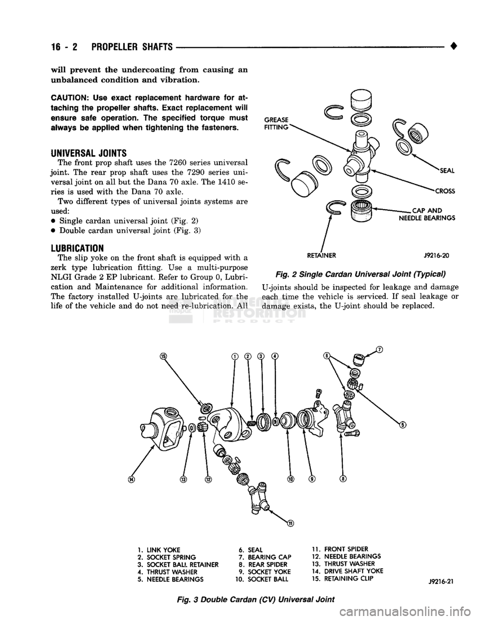
• Single cardan universal joint (Fig. 2)
• Double cardan universal joint (Fig. 3)
LUBRICATION
The slip yoke on the front shaft is equipped with a
zerk type lubrication fitting. Use a multi-purpose NLGI Grade 2 EP lubricant. Refer to Group 0, Lubri
cation and Maintenance for additional information.
The factory installed U-joints are lubricated for the life of the vehicle and do not need re-lubrication. All
RETAINER
J9216-20
Fig.
2
Single
Cardan Universal Joint
(Typical)
U-joints should be inspected for leakage and damage
each time the vehicle is serviced. If seal leakage or damage exists, the U-joint should be replaced.
1.
LINK YOKE
2.
SOCKET SPRING
3. SOCKET BALL RETAINER
4.
THRUST
WASHER
5.
NEEDLE BEARINGS
6.
SEAL
7.
BEARING
CAP
8.
REAR SPIDER
9.
SOCKET YOKE
10.
SOCKET BALL 11.
FRONT
SPIDER
12.
NEEDLE BEARINGS
13.
THRUST
WASHER
14.
DRIVE SHAFT YOKE
15.
RETAINING CLIP
Fig.
3
Double
Cardan (CV) Universal Joint