check engine light DODGE TRUCK 1993 Service Service Manual
[x] Cancel search | Manufacturer: DODGE, Model Year: 1993, Model line: TRUCK, Model: DODGE TRUCK 1993Pages: 1502, PDF Size: 80.97 MB
Page 456 of 1502
•
REAR
WINDOW DEFOGGER
8N - 1
REAR
WINDOW
DEFOGGER
CONTENTS
page
REPAIR
PROCEDURES (GRID LINES,
TERMINALS,
AND
PIGTAILS)
3
GENERAL
INFORMATION
The electrically heated rear window defogger
is
available
on
Ramcharger with sunscreen glass only. The system consists
of a
rear window with
two
ver
tical
bus
bars
and a
series
of
electrically connected
grid lines baked
on the
inside surface. Circuit protection
for the
heated grid circuit
is
pro
vided
by a 18
gauge fusible link wire located
in the
engine compartment.
The
relay circuit
is
protected
by
a 20 amp
fuse, located
in the
fuse block. When
the
rear window defogger switch
is
placed
in
the
ON
position, current
is
directed
to
rear window
grid lines.
The
heated grid lines
in
turn heat
the
rear window
to
clear
the
surface
of fog or
snow.
CAUTION;
Grid lines
can be
damaged
or
scraped
off
with
sharp instruments. Care should
be
taken
in
page
SERVICE
PROCEDURES
4
TEST
PROCEDURES
1
cleaning
the
glass
or
removing foreign materials,
decals
or
stickers. Normal
glass
cleaning solvents
or
hot
water
used
with
rags
or
toweling
is
recom mended.
SYSTEM
DESCRIPTION CONTROL
SWITCH/TIMER
RELAY MODULE
The control switch
and
timer relay
are
integrated
into
a
single panel mounted assembly. Actuating
the
switch energizes
the
electronic timing circuit. This
allows current
to
flow through
the
grid system
for
approximately
10
minutes,
or
until either
the
control
switch
or
ignition
is
turned
off. An
indicating lamp
illuminates
a
lens inlaid
in the
control switch.
TEST PROCEDURES
SYSTEM
TEST
Electrically heated rear window defogger operation
can
be
checked in-vehicle
in the
following manner: (1) Turn
the
ignition
ON.
(2) Turn rear window defogger control switch
ON.
(3) Monitor vehicle voltmeter. With
the
control
switch
ON, a
distinct needle deflection should
be
noted. (4)
The
rear window defogger operation
can be
checked
by
feeling
the
glass.
A
distinct difference
in
temperature between
the
grid lines
and
adjacent clear glass
can be
detected
in 3 to 4
minutes
of
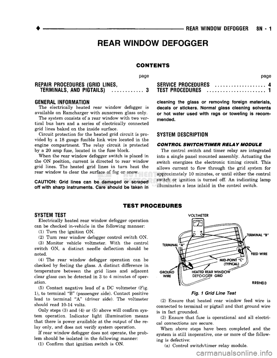
operation. (5) Contact negative lead
of a DC
voltmeter
(Fig.
1),
to
terminal
"B"
(passenger side). Contact positive
lead
to
terminal
"A"
(driver side).
The
voltmeter
should read
10-14
volts. Only steps
(3) and (4) or (5)
above will confirm sys
tem operation. Indicator light illumination means
that there
is
power available
at the
output
of the re
lay only,
and
does
not
verify system operation.
If rear window defogger does
not
operate,
the
prob
lem should
be
isolated
in the
following manner:
(1) Confirm that ignition switch
is ON.
VOLTMETER
Fig.
1
Grid
Line
Test (2) Ensure that heated rear window feed wire
is
connected
to
terminal
or
pigtail
and
that ground wire
is
in
fact grounded.
(3) Ensure that fuse
is
operational
and all
electri
cal connections
are
secure.
When above steps have been completed
and the
system
is
still inoperative,
one or
more
of the
follow
ing
is
defective:
(a) Control switch/timer relay module.
Page 482 of 1502
CAVITY
FUSE/
COLOR ITEMS FUSED
CAVITY
FUSE/
COLOR ITEMS FUSED
10
11
12
13 2 AMP
GY VEHICLE SPEED CONTROL
5 AMP TN
GAUGES,
BRAKE WARNING LAMP, SEAT BELT WARNING
LAMP, BUZZER, LOW OIL LAMP, CHECK ENGINE LAMP,
ANTI-LOCK LAMP, TAILGATE OPEN LAMP, 4WD LAMP, O/D MODULE, LOW FUEL LAMP,
WAIT
TO START LAMP
WATER-IN-FUEL LAMP 14
3 AMP
VT
20 AMP YL BACK-UP LAMP, HEATED REAR WINDOW
15 10 AMP
RD
ILLUMINATION
LAMPS, A/C HEATER LAMP, ASH
RECEIVER LAMP, RADIO LAMP, TRANSMISSION
OVERDRIVE SWITCH LAMP, TACHOMETER LAMP, HEATED REAR WINDOW SWITCH LAMP.
RADIO AND CLOCK MEMORY, POWER MIRRORS, GLOVE BOX LAMP, DOME LAMP, READING LAMP, MAP LAMP,
CARGO LAMP,
IGNITION
SWITCH LAMP, UNDERHOOD LAMP
20 AMP YL FUSE CAVITY #14,
TAIL
LAMPS, PARKING LAMPS, SIDE
AAARKER
LAMPS, LICENSE LAMPS, FRONT AND REAR CLEARANCE LAMPS, RADIO INTENSITY, HORNS
20 AMP YL STOP LAMPS, KEY-IN & HEADLAMP ON BUZZER, RWAL
MODULE 30 AMP
CIRCUIT
BREAKER
TURN
SIGNAL
FLASHER 20 AMP
YL POWER DOOR LOCKS
15 AMP
BL
CIGAR LIGHTER
10 AMP RD RADIO AND CLOCK
20 AMP YL
TURN
SIGNALS, TACHOMETER PROVISION,
RWAL MODULE
20 AMP YL WINDSHIELD WIPERS
30 AMP LG A/C - HEATER BLOWER MOTOR
30 AMP
C/BRKR
POWER WINDOWS
20 AMP YL HAZARD FLASHER
AMPS
FUSE
COLOR
2 GY GRAY
3 VT
VIOLET
5 TN
TAN
10 RD
RED
15
BL
BLUE
20 YL YELLOW
30 LG
LIGHT
GREEN HAZARD
FLASHER
J938W-94
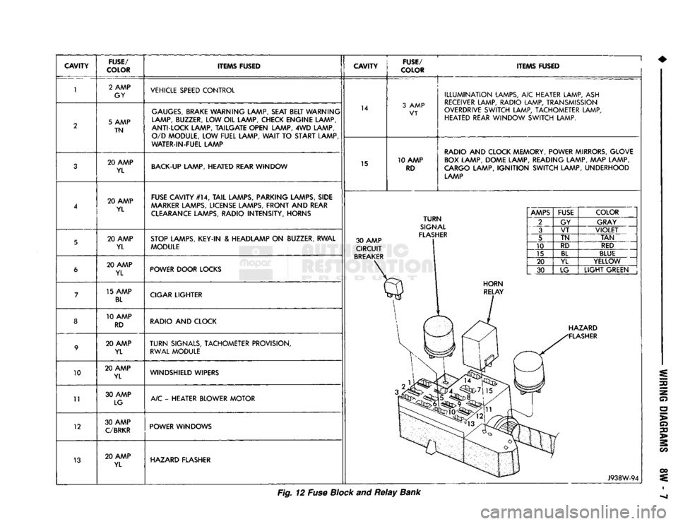
Fig. 12 Fuse Block and
Relay
Bank
Page 607 of 1502
9
- 2
ENGINES
rial surrounds each mounting hole. Excess material
can easily be wiped off. Components should be
torqued in place within 15 minutes. The use of a lo cating dowel is recommended during assembly to pre
vent smearing the material off location.
ENGINE PERFORMANCE
To provide best vehicle performance and lowest ve
hicle emissions, it is most important that the tune-up
be done accurately. Use the specifications listed on
the Vehicle Emission Control Information label found on the engine compartment hood.
(1) Test cranking amperage draw (refer to Group
8B,
Battery/Starter/Generator Service for the proper
procedures).
(2) Tighten the intake manifold bolts (refer to
Group 11, Exhaust System and Intake Manifold for
the proper specifications). (3) Perform cylinder compression test:
(a) Check engine oil level and add oil, if neces
sary.
(b) Drive the vehicle until engine reaches normal
operating temperature. (c) Select a route free from traffic and other
forms of congestion, observe all traffic laws and
briskly accelerate through the gears several times. The higher engine speed may help clean out valve seat deposits which can prevent accurate compres
sion readings.
CAUTION:
DO NOT
overspeed
the
engine.
(d) Remove all spark plugs from engine. As
spark plugs are being removed, check electrodes for
abnormal firing indicators - fouled, hot, oily, etc.
Record cylinder number of spark plug for future
reference.
(e) Disconnect coil wire from distributor and se
cure to good ground to prevent a spark from start
ing a fire.
(f) Be sure throttle blades are fully open during
the compression check. (g) Insert compression gage adaptor into the
No.l spark plug hole. Crank engine until maxi
mum pressure is reached on gauge. Record this
pressure as No.l cylinder pressure.
(h) Repeat Step 3g for all remaining cylinders.
(i) Compression should not be less than 689 kPa
(100 psi) and not vary more than 172 kPa (25 psi)
from cylinder to cylinder.
(j) If cylinder(s) have abnormally low compres
sion pressures, repeat steps 3a through 3h. (k) If the same cylinder(s) repeat an abnormally
low reading, it could indicate the existence of a
problem in the cylinder.
The recommended compression pressures are
to be used only as a guide to diagnosing engine
problems. An engine should NOT be disassem bled to determine the cause of low compression
unless some malfunction is present. (4) Clean or replace spark plugs as necessary. Ad
just gap (refer to Group 8D, Ignition System for gap adjustment and torque).
(5) Test resistance of spark plug cables (refer to
Group 8D, Ignition System.
(6) Inspect the primary wire. Test coil output volt
age,
primary and secondary resistance. Replace parts as necessary (refer to Group 8D, Ignition System and
make necessary adjustment).
(7) Set ignition timing to specifications (refer to
Specification Label on engine compartment hood).
(8) Perform a combustion analysis.
(9) Test fuel pump for pressure and vacuum (refer
to Group 14, Fuel System for the proper specifica
tions).
(10) Inspect air filter element (refer to Group 0,
Lubrication and Maintenance for the proper proce
dure).
(11) Inspect crankcase ventilation system (refer to
Group 0, Lubrication and Maintenance for the proper
procedure).
(12) For emission controls refer to Group 25, Emis
sion Controls System for service procedures.
(13) Inspect and adjust accessory belt drives (refer
to Group 7, Cooling System for the proper adjust
ments).
(14) Road test vehicle as a final test.
H0NIN6
CYLINDER
BORES
Before honing, stuff plenty of clean shop towels un
der the bores and over the crankshaft to keep abra sive materials from entering the crankshaft area.
(1) Used carefully, the Cylinder Bore Sizing Hone
C-823 equipped with 220 grit stones, is the best tool
for this job. In addition to deglazing, it will reduce
taper and out-of-round as well as removing light scuffing, scoring or scratches. Usually a few strokes
will clean up a bore and maintain the required lim
its.
CAUTION:
DO NOT use rigid type
hones
to remove
cylinder
wall
glaze.
(2) Deglazing of the cylinder walls may be done if
the cylinder bore is straight and round. Use a cylin
der surfacing hone, Honing Tool C-3501, equipped
with 280 grit stones (C-3501-3810). 20-60 strokes, de
pending on the bore condition, will be sufficient to
provide a satisfactory surface. Using honing oil C-3501-3880 or a light honing oil available from ma
jor oil distributors.
CAUTION:
DO NOT use engine or
transmission
oil, mineral
spirits
or
kerosene.
Page 632 of 1502
•
3.9L
ENGINE
9 - 27 (2) If valves or seats are reground, check valve
stem height. If valve is too long, replace cylinder
head.
(3) Install new seals on all valve guides. Install
valve springs and valve retainers.
(4) Compress valve springs with Valve Spring
Compressor Tool MD-998772A, install locks and re
lease tool. If valves and/or seats are ground, measure
the installed height of springs. Make sure the mea surement is taken from bottom of spring seat in cyl
inder head to the bottom surface of spring retainer. If
spacers are installed, measure from the top of spacer.
If height is greater than 42.86 mm (1-11/16 inches), install a 1.587 mm (1/16 inch) spacer in head coun-
terbore. This should bring spring height back to nor
mal 41.27 to 42.86 mm (1-5/8 to
1-11/16
inch).
VALVE STEM SEAL
/
SPRING REPLACEMENT
This procedure is done with the cylinder head in
stalled. (1) Set engine basic timing to TDC and remove air
cleaner. (2) Remove cylinder head covers and spark plugs.
(3) Remove coil wire from distributor and secure to
good ground to prevent engine from starting. (4) Using suitable socket and flex handle at crank
shaft retaining bolt, turn engine so the No.l piston is
at Top Dead Center on the compression stroke. (5) Remove rocker arms.
(6) With air hose attached to an adapter installed
in No.l spark plug hole, apply 620-689 kPa (90-100
psi) air pressure. (7) Using Valve Spring Compressor Tool
MD-998772A, compress valve spring and remove re
tainer valve locks and valve spring. (8) Install seals on the exhaust valve stem and po
sition down against valve guides. (9) The intake valve stem seals should be pushed
firmly and squarely over the valve guide using the valve stem as a guide. DO NOT force seal against
top of guide. When installing the valve retainer
locks,
compress the spring only enough to install the
locks.
(10) Follow the same procedure on the remaining 5
cylinders using the firing sequence
1-6-5-4-3-2.
Make sure piston in cylinder is at TDC on the valve spring
that is being removed. (11) Remove adapter from the No.l spark plug
hole.
(12) Install rocker arms.
(13) Install covers and coil wire to distributor.
(14) Install air cleaner.
(15) Road test vehicle.
HYDRAULIC
TAPPETS
Before disassembling any part of the engine to cor
rect tappet noise, check the oil pressure. If vehicle
has no oil pressure gauge, install a reliable gauge at the pressure sending unit. The pressure should be be
tween 207-552 kPa (30-80 psi) at 3,000 RPM.
Check the oil level after the engine reaches normal
operating temperature. Allow 5 minutes to stabilize
oil level, check dipstick.
The oil level in the pan should never be above the
FULL mark or below the ADD OIL mark on dipstick.
Either of these 2 conditions could be responsible for
noisy tappets.
OIL
LEWEL
HIGH
If oil level is above the FULL mark, it is possible
for the connecting rods to dip into the oil. With the engine running, this condition could create foam in
the oil pan. Foam in oil pan would be fed to the hy draulic tappets by the oil pump causing them to lose
length and allow valves to seat noisily.
LOW
Low oil level may allow oil pump to take in air.
When air is fed to the tappets, they lose length
which allows valves to seat noisily. Any leaks on in
take side of oil pump through which air can be drawn will create the same tappet action. Check the
lubrication system from the intake strainer to the
pump cover, including the relief valve retainer cap.
When tappet noise is due to aeration, it may be in
termittent or constant, and usually more than 1 tap
pet will be noisy. When oil level and leaks have been corrected, operate the engine at fast idle. Run engine
for a sufficient time to allow all of the air inside the
tappets to be bled out.
TAPPET
NOISE DIAGNOSIS
(1) To determine source of tappet noise, operate en
gine at idle with cylinder head covers removed. (2) Feel each valve spring or rocker arm to detect
noisy tappet. The noisy tappet will cause the affected
spring and/or rocker arm to vibrate or feel rough in
operation.
Worn valve guides or cocked springs are some
times mistaken for noisy tappets. If such is the
case, noise may be dampened by applying side
thrust on the valve spring. If noise is not appre ciably reduced, it can be assumed the noise is in
the tappet. Inspect the rocker arm push rod sockets and push rod ends for wear.
(3) Valve tappet noise ranges from light noise to a
heavy click. A light noise is usually caused by exces sive leak down around the unit plunger or by the
plunger partially sticking in the tappet body cylin der. The tappet should be replaced. A heavy click is
caused by a tappet check valve not seating or by for
eign particles becoming wedged between the plunger
and the tappet body. This will cause the plunger to
stick in the down position. This heavy click will be
Page 633 of 1502
9
- 28 3.9L
ENGINE
•
accompanied by excessive clearance between the
valve stem and rocker arm as valve closes. In either
case,
tappet assembly should be removed for inspec
tion and cleaning.
The valve train generates a noise very much like a
light tappet noise during normal operation. Care
must be taken to ensure that tappets are making the
noise. In general, if more than one tappet seems to
be noisy, its probably not the tappets.
REMOVAL
(1) Remove the air cleaner.
(2) Remove cylinder head cover.
(3) Remove rocker assembly and push rods. Iden
tify push rods to ensure installation in original loca
tion.
(4) Remove intake manifold.
(5) Remove yoke retainer and aligning yokes.
(6) Slide Hydraulic Tappet Remover/Installer Tool
C-4129-A
through opening in cylinder head and seat
tool firmly in the head of tappet.
(7) Pull tappet out of bore with a twisting motion.
If all tappets are to be removed, identify tappets to
ensure installation in original location. (8) If the tappet or bore in cylinder block is scored,
scuffed, or shows signs of sticking, ream the bore to
next oversize. Replace with oversize tappet.
CAUTION:
The
plunger
and
tappet bodies
are not
interchangeable.
The
plunger
and
valve must
al
ways
be fitted to the
original body.
It is
advisable
to
work
on one
tappet
at a
time
to
avoid mixing
of
parts.
Mixed parts
are not
compatible.
DO NOT
dis
assemble
a
tappet
on a
dirty
work bench.
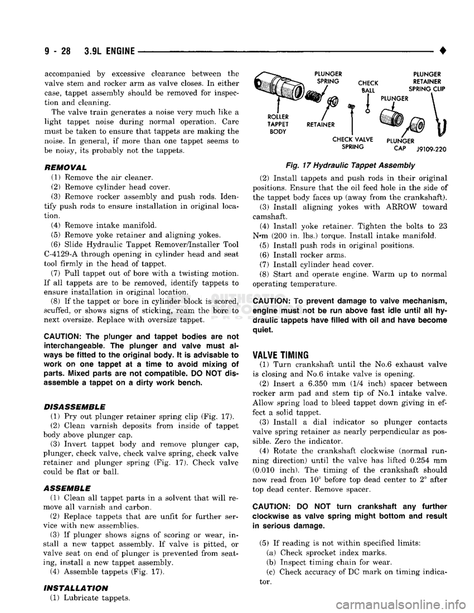
DISASSEMBLE (1) Pry out plunger retainer spring clip (Fig. 17).
(2) Clean varnish deposits from inside of tappet
body above plunger cap.
(3) Invert tappet body and remove plunger cap,
plunger, check valve, check valve spring, check valve retainer and plunger spring (Fig. 17). Check valve
could be flat or ball.
ASSEMBLE (1) Clean all tappet parts in a solvent that will re
move all varnish and carbon.
(2) Replace tappets that are unfit for further ser
vice with new assemblies. (3) If plunger shows signs of scoring or wear, in
stall a new tappet assembly. If valve is pitted, or
valve seat on end of plunger is prevented from seat ing, install a new tappet assembly.
(4) Assemble tappets (Fig. 17).
INSTALLATION
(1) Lubricate tappets.
PLUNGER
SPRING CHECK
BALL PLUNGER
RETAINER
SPRING CLIP
ROLLER
TAPPET
BODY RETAINER
I
PLUNGER
CHECK VALVE
SPRING PLUNGER
CAP
J9109-220
Fig.
17 Hydraulic
Tappet
Assembly
(2) Install tappets and push rods in their original
positions. Ensure that the oil feed hole in the side of
the tappet body faces up (away from the crankshaft).
(3) Install aligning yokes with ARROW toward
camshaft.
(4) Install yoke retainer. Tighten the bolts to 23
N*m (200 in. lbs.) torque. Install intake manifold.
(5) Install push rods in original positions. (6) Install rocker arms.
(7) Install cylinder head cover.
(8) Start and operate engine. Warm up to normal
operating temperature.
CAUTION:
To
prevent damage
to
valve mechanism,
engine must
not be run
above fast idle
until
all hy
draulic tappets have
filled
with
oil and
have become
quiet.
VALVE
TIMING
(1) Turn crankshaft until the No.6 exhaust valve
is closing and No.6 intake valve is opening. (2) Insert a 6.350 mm (1/4 inch) spacer between
rocker arm pad and stem tip of No.l intake valve.
Allow spring load to bleed tappet down giving in ef fect a solid tappet. (3) Install a dial indicator so plunger contacts
valve spring retainer as nearly perpendicular as pos sible. Zero the indicator. (4) Rotate the crankshaft clockwise (normal run
ning direction) until the valve has lifted 0.254 mm (0.010 inch). The timing of the crankshaft should
now read from 10° before top dead center to 2° after
top dead center. Remove spacer.
CAUTION:
DO NOT
turn
crankshaft
any
further
clockwise
as
valve spring might bottom
and
result in serious damage.
(5) If reading is not within specified limits: (a) Check sprocket index marks.
(b) Inspect timing chain for wear. (c) Check accuracy of DC mark on timing indica
tor.
Page 644 of 1502
•
3.9L
ENGINE
9 - 39 (2) Remove the oil pump from the rear main bear
ing cap.
(8)
Identify bearing caps before removal. Remove
bearing caps and bearings one at a time.
(4) Lift the crankshaft out of the block.
(5) Remove and discard the crankshaft rear oil
seals.
(6)
Remove and discard the front crankshaft oil
seal.
INSPECTION OF JOURNALS The crankshaft connecting rod and main journals
should be checked for excessive wear, taper and scor
ing. The maximum taper or out-of-round on any
crankshaft journal is 0.025 mm (0.001 inch).
Journal grinding should not exceed 0.305 mm
(0.012 inch) under the standard journal diameter. DO
NOT grind thrust faces of No.3 main bearing. DO
NOT nick crank pin or bearing fillets. After grind
ing, remove rough edges from crankshaft oil holes and clean out all oil passages.
CAUTION:
After any journal
grind,
it is important
that
the
final
paper or cloth
polish
be in the
same
direction as the engine rotates.
INSTALLATION (1) Lightly oil the new upper seal lips with engine
oil.
(2) Install the new upper rear bearing oil seal with
the yellow paint facing towards the rear of the en
gine.
(3) Position the crankshaft into the cylinder block.
(4) Lightly oil the new lower seal lips with engine
oil.
(5) Install the new lower rear bearing oil seal into
the bearing cap with the yellow paint facing towards the rear of the engine.
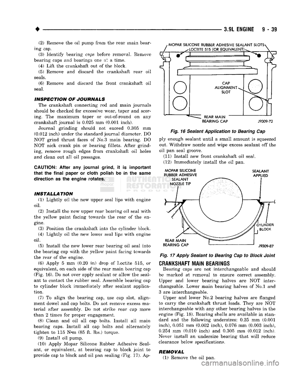
(6) Apply 5 mm (0.20 in) drop of Loctite 515, or
equivalent, on each side of the rear main bearing cap (Fig. 16). Do not over apply sealant or allow the seal
ant to contact the rubber seal. Assemble bearing cap
to cylinder block immediately after sealant applica tion.
(7) To align the bearing cap, use cap slot, align
ment dowel and cap bolts. Do not remove excess ma
terial after assembly. Do not strike rear cap more
than 2 times for proper engagement.
(8) Clean and oil all cap bolts. Install all main
bearing caps. Install all cap bolts and alternately
tighten to 115 N»m (85 ft. lbs.) torque.
(9)
Install oil pump.
(10) Apply Mopar Silicone Rubber Adhesive Seal
ant, or equivalent, at bearing cap to block joint to
provide cap to block and oil pan sealing (Fig. 17). Ap-
BEARING CAP
J9309-72
Fig.
16 Sealant Application to Bearing Cap ply enough sealant until a small amount is squeezed
out. Withdraw nozzle and wipe excess sealant off the
oil pan seal groove.
(11) Install new front crankshaft oil seal. (12) Immediately install the oil pan.
MOPAR SILICONE SEALANT
RUBBER
ADHESIVE APPLIED
Fig.
17
Apply
Sealant to Bearing Cap to
Block
Joint
CRANKSHAFT MAIN BEARINGS
Bearing caps are not interchangeable and should
be marked at removal to ensure correct assembly.
Upper and lower bearing halves are NOT inter changeable. Lower main bearing halves of No.l and
3 are interchangeable. Upper and lower No.2 bearing halves are flanged
to carry the crankshaft thrust loads. They are NOT interchangeable with any other bearing halves in the
engine (Fig. 18). Bearing shells are available in stan
dard and the following undersizes: 0.25 mm (0.001
inch),
0.051 mm (0.002 inch), 0.076 mm (0.003 inch),
0.254 mm (0.010 inch) and 0.305 mm (0.012 inch).
Never install an undersize bearing that will reduce
clearance below specifications.
REMOVAL (1) Remove the oil pan.
Page 646 of 1502
•
3.9L ENGINE
9 - 41 (3) Remove the rear main bearing cap. Remove
and discard the old lower oil seal.
(4) Carefully remove and discard the old upper oil
seal.
(5) Lightly oil the new upper seal lips with engine
oil.
To allow ease of installation of the seal, loosen at
least the 2 main bearing caps forward of the rear
bearing cap.
(6) Rotate the new upper seal into the cylinder
block being careful not to shave or cut the outer sur face of the seal. To assure proper installation, use the installation tool provided with the kit. Install the
new seal with the yellow paint facing towards the
rear of the engine.
(7) Install the new lower rear bearing oil seal into
the bearing cap with the yellow paint facing towards
the rear of the engine.
(8) Apply 5 mm (0.20 in) drop of Loctite 515, or
equivalent, on each side of the rear main bearing cap (Fig. 16). Do not over apply sealant or allow the seal
ant to contact the rubber seal. Assemble bearing cap
to cylinder block immediately after sealant applica
tion. Be sure the yellow paint faces toward the rear of the engine.
(9) To align the bearing cap, use cap slot, align
ment dowel and cap bolts. Do not remove excess ma
terial after assembly. Do not strike rear cap more
than 2 times for proper engagement.
(10) Install the rear main bearing cap with cleaned
and oiled cap bolts. Alternately tighten ALL cap
bolts to 115 N-m (85 ft. lbs.) torque.
(11) Install oil pump.
(12) Apply Mopar Silicone Rubber Adhesive Seal
ant, or equivalent, at bearing cap to block joint to
provide cap to block and oil pan sealing (Fig. 17). Ap
ply enough sealant until a small amount is squeezed out. Withdraw nozzle and wipe excess sealant off the
oil pan seal groove.
(13) Immediately install the oil pan.
LOWER SEAL REPLACEMENT
(1) Remove the oil pan.
(2) Remove the oil pump from the rear main bear
ing cap.
(3) Remove the rear main bearing cap and discard
the old lower seal.
(4) Carefully install a new upper seal (refer to Up
per Seal Replacement - Crankshaft Installed proce dure above).
(5) Lightly oil the new lower seal lips with engine
oil.
(6) Install a new lower seal in bearing cap with
yellow paint facing the rear of engine. (7) Apply 5 mm (0.20 in) drop of Loctite 515, or
equivalent, on each side of the rear main bearing cap (Fig. 16). Do not over apply sealant or allow the seal ant to contact the rubber seal. Assemble bearing cap
to cylinder block immediately after sealant applica tion.
(8) To align the bearing cap, use cap slot, align
ment dowel and cap bolts. Do not remove excess ma
terial after assembly. Do not strike rear cap more
than 2 times for proper engagement.
(9) Install the rear main bearing cap with cleaned
and oiled cap bolts. Alternately tighten the cap bolts
to 115 Nnn (85 ft. lbs.) torque.
(10) Install oil pump.
(11) Apply Mopar Silicone Rubber Adhesive Seal
ant, or equivalent, at bearing cap to block joint to
provide cap to block and oil pan sealing (Fig. 17). Ap
ply enough sealant until a small amount is squeezed out. Withdraw nozzle and wipe excess sealant off the
oil pan seal groove.
(12) Immediately install the oil pan.
CYLINDER
BLOCK
Remove the engine assembly from the vehicle.
DISASSEMBLE
(1) Remove the cylinder head. (2) Remove the oil pan.
(3) Remove the piston/connecting rod assembly.
CLEANING
Clean cylinder block thoroughly and check all core
hole plugs for evidence of leaking.
INSPECTION
Examine block for cracks or fractures.
The cylinder walls should be checked for
out-of-
round and taper with Cylinder Bore Indicator Tool C-119. The cylinder block should be bored and honed
with new pistons and rings fitted if:
• The cylinder bores show more than 0.127 mm (0.005 inch) out-of-round.
• The cylinder bores show a taper of more than 0.254 mm (0.010 inch).
• The cylinder walls are badly scuffed or scored. Boring and honing operation should be closely co
ordinated with the fitting of pistons and rings so specified clearances may be maintained.
Refer to Standard Service Procedures in the begin
ning of this Group for the proper honing of cylinder
bores.
OIL LINE PLUG
The oil line plug is located in the vertical passage
at the rear of the block between the Oil-To-Filter and
Oil-From-Filter passages (Fig. 20). Improper installa
tion or plug missing could cause erratic, low or no oil pressure.
(1) Remove oil pressure sending unit from back of
block.
Page 660 of 1502
•
5.2L
ENGINE
I - 55
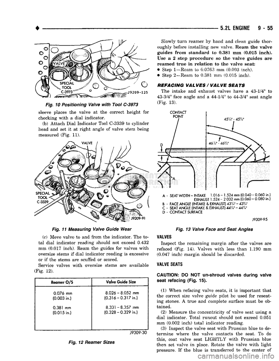
Fig. 10 Positioning Valve with Tool C-3973 sleeve places the valve at the correct height for
checking with a dial indicator.
(b) Attach Dial Indicator Tool C-3339 to cylinder
head and set it at right angle of valve stem being measured (Fig. 11).
Fig. 11 Measuring Valve Guide Wear
(c) Move valve to and from the indicator. The to
tal dial indicator reading should not exceed
0.432
mm
(0.017
inch). Ream the guides for valves with
oversize stems if dial indicator reading is excessive
or if the stems are scuffed or scored. Service valves with oversize stems are available
(Fig. 12).
Reamer
O/S
Valve
Guide
Size
0.076
mm
8.026
-
8.052
mm
(0.003
in.)
(0.316-0.317in.)
0.381
mm
8.331
-
8.357
mm
(0.015
In.)
(0.328-0.329
In.)
J9309-30
Fig. 12 Reamer Sizes
Slowly turn reamer
by
hand
and
clean guide thor
oughly before installing
new
valve. Ream
the valve
guides from standard
to 0,381 mm
(0.015 Inch).
Use
a 2
step procedure
so the
valve guides
are
reamed true
in
relation
to the
valve seat:
• Step
1-Ream
to 0.0763 mm (0.003 inch),
• Step 2—Ream, to 0.381 mm (0.015 inch).
REFACING
VAL
WES
/
WAL
WE
SEATS
The intake and exhaust valves have a 43-1/4° to
43-3/4° face angle and a 44-1/4° to 44-3/4° seat angle
(Fig.
13).
CONTACT
A
-
SEAT
WIDTH
-
INTAKE
1.016-1.524
mm
(0.040
-
0.060
in.)
EXHAUST
1.524 -
2.032
mm
(0.060
-
0.080
in.)
B
-
FACE ANGLE (INTAKE
&
EXHAUST)
437.°
-433//
C
-
SEAT ANGLE (INTAKE
&
EXHAUST)
447/ - 447/
D
-
CONTACT SURFACE
J9309-95
Fig. 13 Valve Face and Seat Angles
VALVES
Inspect the remaining margin after the valves are
refaced (Fig. 14). Valves with less than 1.190 mm (0.047 inch) margin should be discarded.
VALVE
SEATS
CAUTION:
DO NOT
un-shroud valves
during
valve
seat
refacing (Fig.
15).
(1) When refacing valve seats, it is important that
the correct size valve guide pilot be used for reseat ing stones. A true and complete surface must be ob
tained.
(2) Measure the concentricity of valve seat using a
dial indicator. Total runout should not exceed 0.051
mm (0.002 inch) total indicator reading. (3) Inspect the valve seat with Prussian blue to de
termine where the valve contacts the seat. To do
this,
coat valve seat LIGHTLY with Prussian blue
then set valve in place. Rotate the valve with light
pressure. If the blue is transferred to the center of
Page 662 of 1502
•
5.2L
ENGINE
9 - 57 (6) With air hose attached to an adapter installed
in No.l spark plug hole, apply 620-689 kPa (90-100
psi) air pressure.
(7) Using Valve Spring Compressor Tool
MD-998772A, compress valve spring and remove re
tainer valve locks and valve spring.
(8) Install seals on the exhaust valve stem and po
sition down against valve guides.
(9) The intake valve stem seals should be pushed
firmly and squarely over the valve guide using the valve stem as a guide. DO NOT force seal against
top of guide. When installing the valve retainer
locks,
compress the spring only enough to install the
locks.
(10) Follow the same procedure on the remaining 7
cylinders using the firing sequence 1-8-4-3-6-5-7-2.
Make sure piston in cylinder is at TDC on the valve
spring that is being removed. (11) Remove adapter from the No.l spark plug
hole.
(12) Install rocker arms.
(13) Install covers and coil wire to distributor.
(14) Install air cleaner. (15) Road test vehicle.
HYDRAULIC TAPPETS
Before disassembling any part of the engine to cor
rect tappet noise, check the oil pressure. If vehicle
has no oil pressure gauge, install a reliable gauge at the pressure sending unit. The pressure should be be
tween 207-552 kPa (30-80 psi) at 3,000 RPM. Check the oil level after the engine reaches normal
operating temperature. Allow 5 minutes to stabilize oil level, check dipstick. The oil level in the pan should never be above the
FULL mark or below the ADD OIL mark on dipstick.
Either of these 2 conditions could be responsible for
noisy tappets.
OIL LEWEL
HIGH
If oil level is above the FULL mark, it is possible
for the connecting rods to dip into the oil. With the
engine running this condition could create foam in
the oil pan. Foam in oil pan would be fed to the hy
draulic tappets by the oil pump causing them to lose
length and allow valves to seat noisily.
LOW Low oil level may allow oil pump to take in air.
When air is fed to the tappets, they lose length
which allows valves to seat noisily. Any leaks on in
take side of oil pump through which air can be drawn will create the same tappet action. Check the
lubrication system from the intake strainer to the
pump cover, including the relief valve retainer cap. When tappet noise is due to aeration, it may be in termittent or constant, and usually more than 1 tap
pet will be noisy. When oil level and leaks have been
corrected, operate the engine at fast idle. Run engine
for a sufficient time to allow all of the air inside the
tappets to be bled out.
TAPPET
NOISE DIAGNOSIS
(1) To determine source of tappet noise, operate en
gine at idle with cylinder head covers removed.
(2) Feel each valve spring or rocker arm to detect
noisy tappet. The noisy tappet will cause the affected
spring and/or rocker arm to vibrate or feel rough in
operation.
Worn valve guides or cocked springs are some
times mistaken for noisy tappets. If such is the case, noise may be dampened by applying side
thrust on the valve spring. If noise is not appre
ciably reduced, it can be assumed the noise is in
the tappet. Inspect the rocker arm push rod sockets and push rod ends for wear.
(3) Valve tappet noise ranges from light noise to a
heavy click. A light noise is usually caused by exces sive leak-down around the unit plunger or by the
plunger partially sticking in the tappet body cylin der. The tappet should be replaced. A heavy click is caused by a tappet check valve not seating or by for
eign particles becoming wedged between the plunger and the tappet body. This will cause the plunger to
stick in the down position. This heavy click will be accompanied by excessive clearance between the
valve stem and rocker arm as valve closes. In either
case,
tappet assembly should be removed for inspec
tion and cleaning.
The valve train generates a noise very much like a
light tappet noise during normal operation. Care
must be taken to ensure that tappets are making the
noise. In general, if more than one tappet seems to
be noisy, its probably not the tappets.
REMOVAL
(1) Remove the air cleaner.
(2) Remove cylinder head cover.
(3) Remove rocker assembly and push rods. Iden
tify push rods to ensure installation in original loca
tion.
(4) Remove intake manifold.
(5) Remove yoke retainer and aligning yokes.
(6) Slide Hydraulic Tappet Remover/Installer Tool
C-4129-A through opening in cylinder head and seat
tool firmly in the head of tappet.
(7) Pull tappet out of bore with a twisting motion.
If all tappets are to be removed, identify tappets to
ensure installation in original location.
(8) If the tappet or bore in cylinder block is scored,
scuffed, or shows signs of sticking, ream the bore to
next oversize. Replace with oversize tappet.
Page 673 of 1502
9
- 68 5.2L
ENGINE
• INSTALLATION
(1) Be sure that compression ring gaps are stag
gered so that neither is in-line with oil ring rail gap.
(2) Before installing the ring compressor, make
sure the oil ring expander ends are butted and the
rail gaps located properly (Fig. 14).
(3) Immerse the piston head and rings in clean en
gine oil. Slide Piston Ring Compressor Tool C-385
over the piston and tighten with the special wrench (part of Tool C-385). Be sure position of rings does
not change during this operation.
(4) Install connecting rod bolt protectors on rod
bolts,
the long protector should be installed on the numbered side of the connecting rod. (5) Rotate crankshaft so that the connecting rod
journal is on the center of the cylinder bore. Be sure connecting rod and cylinder bore number are the same. Insert rod and piston into cylinder bore and
guide rod over the crankshaft journal.
(6) Tap the piston down in cylinder bore, using a
hammer handle. At the same time, guide connecting rod into position on crankshaft journal.
(7) The notch or groove on top of piston must be
pointing toward front of engine. The larger chamfer
of the connecting rod bore must be installed toward
crankshaft journal fillet.
(8) Install rod caps. Be sure connecting rod, con
necting rod cap and cylinder bore number are the same. Install nuts on cleaned and oiled rod bolts and
tighten nuts to 61 N®m (45 ft. lbs.) torque.
(9) Install the oil pan.
(10) Install the cylinder head.
(11) Install the engine into the vehicle.
CRANKSHAFT
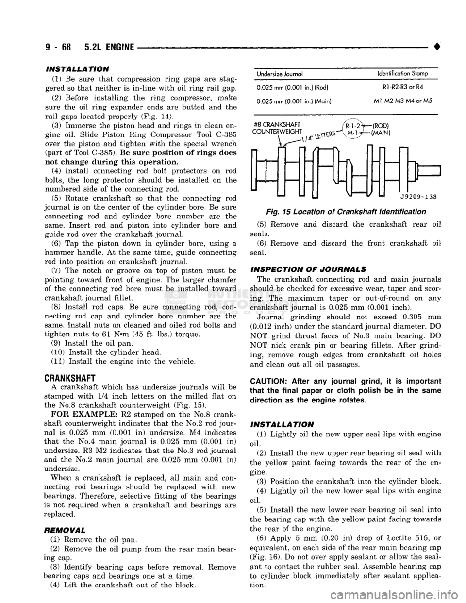
A crankshaft which has undersize journals will be
stamped with 1/4 inch letters on the milled flat on
the No.8 crankshaft counterweight (Fig. 15).
FOR
EXAMPLE: R2 stamped on the No.8 crank
shaft counterweight indicates that the No.2 rod jour
nal is 0.025 mm (0.001 in) undersize. M4 indicates
that the No.4 main journal is 0.025 mm (0.001 in) undersize. R3 M2 indicates that the No.3 rod journal and the No.2 main journal are 0.025 mm (0.Q01 in)
undersize. When a crankshaft is replaced, all main and con
necting rod bearings should be replaced with new
bearings. Therefore, selective fitting of the bearings is not required when a crankshaft and bearings are
replaced.
REMOVAL (1) Remove the oil pan.
(2) Remove the oil pump from the rear main bear
ing cap. (3) Identify bearing caps before removal. Remove
bearing caps and bearings one at a time. (4) Lift the crankshaft out of the block.
Undersize
Journal
Identification
Stamp
0.025
mm
(0.001
in.)
(Rod)
R1-R2-R3
or R4
0.025
mm
(0.001
in.) (Main)
M1-M2-M3-M4
or M5
#8
CRANKSHAFT
COUNTERWEIGHT
(ROD)
(MAIN)
f
J9209-138
Fig.
15 Location of Crankshaft
Identification
(5) Remove and discard the crankshaft rear oil
seals.
(6) Remove and discard the front crankshaft oil
seal.
INSPECTION OF JOURNALS The crankshaft connecting rod and main journals
should be checked for excessive wear, taper and scor
ing. The maximum taper or out-of-round on any crankshaft journal is 0.025 mm (0.001 inch). Journal grinding should not exceed 0.305 mm
(0.012 inch) under the standard journal diameter. DO
NOT grind thrust faces of No.3 main bearing. DO
NOT nick crank pin or bearing fillets. After grind ing, remove rough edges from crankshaft oil holes
and clean out all oil passages.
CAUTION:
After any journal
grind,
it is important
that
the
final
paper or cloth
polish
be in the
same
direction as the engine rotates.
INSTALLATION (1) Lightly oil the new upper seal lips with engine
oil.
(2) Install the new upper rear bearing oil seal with
the yellow paint facing towards the rear of the en
gine.
(3) Position the crankshaft into the cylinder block.
(4) Lightly oil the new lower seal lips with engine
oil.
(5) Install the new lower rear bearing oil seal into
the bearing cap with the yellow paint facing towards
the rear of the engine.
(6)
Apply 5 mm (0.20 in) drop of Loctite 515, or
equivalent, on each side of the rear main bearing cap (Fig. 16). Do not over apply sealant or allow the seal
ant to contact the rubber seal. Assemble bearing cap
to cylinder block immediately after sealant applica tion.