oil DODGE TRUCK 1993 Service Manual PDF
[x] Cancel search | Manufacturer: DODGE, Model Year: 1993, Model line: TRUCK, Model: DODGE TRUCK 1993Pages: 1502, PDF Size: 80.97 MB
Page 190 of 1502
•
BRAKES
i - 3 BRAKE DIAGNOSIS
INDEX
page
Brake
Warning Lights
3
Diagnosing
Brake Problems .................
4
Diagnosis
Procedures
3
Low
Vacuum
Switch—Diesel
Models
3
page
Master
Cylinder/Power Booster Test
5
Power
Booster
Check
Valve Test .............
6
Power
Booster
Vacuum
Test .................
6
Testing Diesel
Engine
Vacuum
Pump
Output
.... 6
DIAGNOSIS
PROCEDURES
Brake diagnosis involves determining
if the
prob
lem
is
related
to a
mechanical, hydraulic
or
vacuum
operated component.
A
preliminary check, road test
ing
and
component inspection
can all be
used
to de
termine
a
problem cause. Road testing will either verify proper brake opera
tion
or
confirm
the
existence
of a
problem. Compo nent inspection will,
in
most cases, identify
the
actual part causing
a
problem. The first diagnosis step
is the
preliminary check. This
involves inspecting fluid level, parking brake action,
wheel
and
tire condition, checking
for
obvious leaks
or
component damage
and
testing brake pedal response. A road test will confirm
the
existence
of a
problem.
Final diagnosis procedure involves road test analysis and
a
visual inspection
of
brake components.
BRAKE
WARNING LIGHTS
The
red
brake warning light
is
connected
to the
parking brake switch
and to the
pressure differential switch
in the
combination valve. The
red
light will illuminate when
the
parking
brakes
are
applied
or
when
a
fluid pressure drop
oc
curs
in the
front
or
rear brake circuit.
The
light will
also illuminate
for
approximately
2-4
seconds
at en
gine start
up.
This
is a
self test feature designed
to
check bulb
and
circuit operation each time
the en
gine
is
started. The amber antilock light
is
connected
to the
anti-
lock rear brake hydraulic valve.
The
light will illu
minate
if a
fault occurs within
the
antilock system.
LOW VACUUM SWITCH-DIESEL MODELS
On diesel models,
the red
brake warning light
is
also
used
to
alert
the
driver
of a low
brake booster vacuum
condition.
The
warning light
is in
circuit with
a
vacuum
warning switch mounted
on the
driver side fender
panel.
The
vacuum side
of the
switch
is
connected
to the
power brake booster.
The
electrical side
of the
switch
is
connected
to the
brake warning light. The
low
vacuum switch monitors booster vacuum
level whenever
the
engine
is
running.
If
booster vac
uum falls below
8.5
inches vacuum
for a
minimum
of
10 seconds,
the
switch completes
the
circuit
to the
warning light causing
it to
illuminate.
The
warning light
is
designed
to
differentiate between
a low
vac
uum condition
and a
hydraulic circuit fault.
PRELIMINARY
BRAKE CHECK
(1) Check condition
of
tires
and
wheels. Damaged
wheels
and
worn, damaged,
or
underinflated tires
can
cause pull, shudder, tramp,
and a
condition similar
to
grab.
(2)
If
complaint
was
based
on
noise when braking,
check suspension components. Jounce front
and
rear
of
vehicle
and
listen
for
noise that might
be
caused
by
loose, worn
or
damaged suspension
or
steering compo
nents.
(3) Inspect brake fluid level
and
condition. Note
that
the
front disc brake reservoir fluid level will drop
in
proportion
to
normal lining wear. Also note
that brake fluid tends
to
darken over time. This
is normal
and
should
not be
mistaken
for
con
tamination.
If the
fluid
is
still clear
and
free
of
foreign material,
it is OK.
(a)
If
fluid level
is
abnormally
low,
look
for
evi
dence
of
leaks
at
calipers, wheel cylinders, brake-
lines
and
master cylinder.
(b)
If
fluid appears contaminated, drain
out a
sample.
If
fluid
is
separated into layers,
or
obvi
ously contains
oil or a
substance other than brake
fluid,
the
system seals
and
cups will have
to be re
placed
and the
hydraulic system flushed.
(4) Check parking brake operation. Verify free
movement
and
full release
of
cables
and
pedal. Also
note
if
vehicle
was
being operated with parking
brake partially applied.
(5) Check brake pedal operation. Verify that pedal
does
not
bind
and has
adequate free play.
If
pedal
lacks free play, check pedal
and
power booster
for be
ing loose
or for
bind condition.
Do not
road test until
condition
is
corrected.
(6)
If
components checked appear
OK,
road test
the
vehicle.
ROAD
TESTING (1)
If
complaint involved
low
brake pedal, pump
the pedal
and
note
if the
pedal comes back
up to
nor mal height.
(2) Check brake pedal response with transmission
in Neutral
and
engine running. Pedal should remain
firm under steady foot pressure.
Page 192 of 1502
•
BRAKES
5 - 5 Disc brake rotors with excessive lateral runout or
thickness variation, or out of round brake drums are
the primary causes of pulsation. Other causes are loose
wheel bearings or calipers and worn, damaged tires.
PULL A
front pull condition could be the result of con
taminated lining in one caliper, seized caliper piston,
binding caliper, loose caliper, loose or corroded slide
pins,
improper brakeshoes, or a damaged rotor.
A worn, damaged wheel bearing or suspension compo
nent are further causes of pull. A damaged front tire (bruised, ply separation) can also cause pull.
A common and frequently misdiagnosed pull condi
tion is where direction of pull changes after a few
stops.
The cause is a combination of brake drag fol
lowed by fade at one of the brake units.
As the dragging brake overheats, efficiency is so
reduced that fade occurs. Since the opposite brake
unit is still functioning normally, its braking effect is
magnified. This causes pull to switch direction in fa
vor of the normally functioning brake unit.
When diagnosing a change in pull condition, re
member that pull will return to the original direction
if the dragging brake unit is allowed to cool down (and is not seriously damaged).
REAR BRAKE GRAB
OR
PULL
Rear grab or pull is usually caused by an improperly
adjusted or seized parking brake cable, contaminated
lining, bent or binding shoes and support plates, or im
properly assembled components. This is particularly
true when only one rear wheel is involved. However,
when both rear wheels are affected, the master cylinder or proportioning valve could be at fault.
BRAKES
DO NOT
HOLD
AFTER
DRIVING
THROUGH
DEEP
WATER
PUDDLES
This condition is generally caused by water soaked
lining. If the lining is only wet, it can be dried by driv
ing with the brakes very lightly applied for a few min
utes.
However, if the lining is thoroughly wet and dirty,
disassembly and cleaning will be necessary.
BRAKE NOISE
Squeak/Squeal
Brake squeak or squeal may be due to linings that
are wet or contaminated with brake fluid, grease, or oil. Glazed linings and rotors with hard spots can also con
tribute to squeak. Dirt and foreign material embedded in the brake lining can also cause squeak/squeal.
A very loud squeak or squeal is frequently a sign of
severely worn brake lining. If the lining has worn
through to the brakeshoes in spots, metal-to-metal con
tact occurs. If the condition is allowed to continue, ro tors can become so scored that replacement is necessary.
Thump/Clunk
Thumping or clunk noises during braking are fre
quently not caused by brake components. In many
cases,
such noises are caused by loose or damaged steering, suspension, or engine components. How
ever, calipers that bind on the slide pins, or slide sur
faces,
can generate a thump or clunk noise. Worn
out, improperly adjusted, or improperly assembled
rear brakeshoes can also produce a thump noise.
Chatter
Brake chatter is usually caused by loose or worn
components, or glazed/burnt lining. Rotors with hard
spots can also contribute to chatter. Additional
causes of chatter are out of tolerance rotors, brake
lining not securely attached to the shoes, loose wheel
bearings and contaminated brake lining.
Brakelining Contamination Brakelining contamination is usually a product of
leaking calipers or wheel cylinders, driving through
deep water puddles, or lining that has become cov
ered with grease and grit during repair.
Wheel and
Tire
Problems Some conditions attributed to brake components
may actually be caused by a wheel or tire problem.
A damaged wheel can cause shudder, vibration and
pull. A worn or damaged tire can also cause pull.
Severely worn tires with very little tread left can
produce a grab-like condition as the tire loses and re covers traction. Flat-spotted tires can cause vibration and wheel
tramp and generate shudder during brake operation. A tire with internal damage such as a severe
bruise or ply separation can cause pull and vibration.
MASTER
CYLINDER/POWER BOOSTER TEST
(1) Start engine and check booster vacuum hose
connections. Hissing noise indicates a vacuum leak. Correct any leaks before proceeding. (2) Stop engine and shift transmission into Neu
tral (3) Pump brake pedal until all vacuum reserve in
booster is depleted. (4) Press and hold brake pedal under light foot
pressure. (a) If pedal holds firm, proceed to step (5).
(b) If pedal does not hold firm and falls away,
master cylinder is faulty (internal leakage). (5) Start engine and note pedal action. (a) If pedal falls away slightly under light foot
pressure then holds firm, proceed to step (6). (b) If pedal is effort is high, or no pedal action is
discernible, power booster or vacuum check valve is
faulty. Install known good check valve and repeat steps (2) through (5).
Page 194 of 1502
•
BRAKES
i - 7
BRAKE
ADJUSTMENTS-BRAKE
BLEEDING
INDEX
page
Brake
Fluid and Level 7
Brake
System
Bleeding 8
Rear
Brake
Adjustment 7
BRAKE
FLUID
AND
LEWEL
RECOMMENDED
FLUID The only brake fluid recommended for AD models
is Mopar brake fluid, or an equivalent fluid meeting SAE
J1703
and DOT 3 standards.
Use new brake fluid only, to top off the master
cylinder or refill the system* Never use re
claimed fluid, fluid not meeting the
SAE/DOT
standards, fluid marked 70R1, or fluid from a
container that has been left open for any length
of time. Using non recommended or unspecified
fluid can result in brake failure after hard pro longed braking.
BRAKE
FLUID
LEWEL Always clean the master cylinder cover before
checking fluid level. If not cleaned, dirt from the
cover could enter the fluid. Also check the cover seal
and replace it if torn or distorted.
Correct fluid level is to the bottom of the ring in
dicators on models with a plastic reservoir and to
within 1/4 inch of the reservoir rim on all others. If necessary, add fluid to bring up to the proper level.
Note that on disc brake equipped vehicles, fluid level can be expected to fall as the brake pads wear.
BRAKE
FLUID
CONTAMINATION
Oil in the fluid will cause brake system rubber
seals to soften and swell. The seals may also become
porous and begin to deteriorate.
If fluid contamination is suspected, drain off a sam
ple from the master cylinder. A suction gun or simi lar device can be used for this purpose.
Empty the drained fluid into a glass container.
Contaminants in the fluid will cause the fluid to sep
arate into distinct layers. If contamination has oc
curred, the system rubber seals, hoses and cups must
be replaced and the system thoroughly flushed with clean brake fluid.
Remember that brake fluid tends to darken
over time. Do not confuse this normal condition
with contamination.
REAR
BRAKE
ADJUSTMENT
The rear drum brakes are equipped with a self ad
justing mechanism. Under normal circumstances, the only time adjustment is required is when the brake-
page
Stop
Light Switch Adjustment 9
Wheel
Nut Tightening 9
shoes are replaced; removed for access to other parts; or when one or both drums are replaced.
Adjustment can be performed with a standard
brake gauge or with adjusting tool C-3784.
ADJUSTMENT
WITH
STANDARD
BRAKE
GAUGE
(1) Verify that left/right automatic adjuster lever
and cable are properly connected and that parking
brakes are fully released. Be sure there is slack in cables.
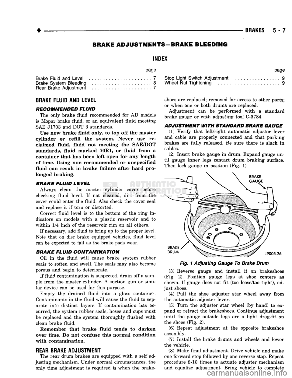
(2) Insert brake gauge in drum. Expand gauge un
til gauge inner legs contact drum braking surface. Then lock gauge in position (Fig. 1).
Fig.
1 Adjusting Gauge To Brake
Drum
(3) Reverse gauge and install it on brakeshoes
(Fig. 2). Position gauge legs at shoe centers as
shown. If gauge does not fit (too loose/too tight), ad
just shoes. (4) Pull the shoe adjuster star wheel away from
the automatic adjuster lever.
(5) Turn the adjuster star wheel (by hand) to ex
pand or retract the brakeshoes. Continue adjustment until the gauge outside legs are a light drag-fit on
the shoes (Fig. 2).
(6) Repeat adjustment at the opposite brakeshoe
assembly. (7) Install the brake drums and wheels and lower
the vehicle.
(8) Make final adjustment. Drive vehicle and make
one forward stop followed by one reverse stop. Repeat
procedure 8-10 times to actuate adjuster mechanism and equalize adjustment. Bring vehicle to complete
Page 200 of 1502
•
BRAKES
5 - 13
COMBINATION VALVE OPERATION
METERING (HOLD-OFF) VALVE The metering valve is used to balance brake action
between the front disc and rear drum brakes. The
valve meters (holds-off) full apply pressure to the front disc brakes until the rear brakeshoes are in full
contact with the drums.
The valve is designed to maintain front brake fluid
pressure at 3-30 psi until the hold-off limit of 117 psi is reached. At this point, the metering valve opens completely permitting full fluid apply pressure to the
front disc brakes.
PRESSURE DIFFERENTIAL SWITCH AND VALVE The pressure differential switch is connected to the
brake warning light. The switch is triggered by movement of the switch valve. The purpose of the switch is to monitor fluid pressure in the separate
front/rear brake hydraulic circuits.
A decrease or loss of fluid pressure in either hy
draulic circuit will cause the switch valve to shuttle
forward or rearward in response to a pressure differ ential.
Movement of the switch valve will push the switch
plunger upward. This closes the switch internal con tacts completing the electrical circuit to the warning light. The switch valve will remain in an actuated
position until repair restores system pressures to nor mal levels.
COMBINATION VALVE TESTING
TESTING METERING VALVE Metering valve operation can be checked visually
and with the aid of a helper.
Observe the metering valve stem while a helper
applies and releases the brakes. If the valve is oper
ating correctly, the stem will extend slightly when
the brakes are applied and retract when the brakes are released.
If the valve is faulty, replace the entire combina
tion valve as an assembly.
TESTING PRESSURE DIFFERENTIAL SWITCH (1) Have helper sit in drivers seat to observe brake
warning light and to operate brake pedal.
(2) Raise vehicle on hoist.
(3) Connect bleed hose to left or right rear wheel
cylinder. Then immerse hose end in glass jar par
tially filled with brake fluid.
(4) Have helper press and hold brake pedal all the
way down and observe warning light.
(a) If warning light illuminates, switch is operat
ing correctly. (b) If light fails to illuminate, check circuit fuse,
bulb and wiring. Repair as necessary and repeat test steps (3) and (4). (5) If warning light still fails to illuminate, check
brakelight and park brake switches (and wiring) with test lamp. Repair or replace parts as necessary and test differential pressure switch operation again.
(6) If warning light still does not illuminate,
switch is faulty. Replace combination valve, bleed
brakes and verify proper switch and valve operation.
COMBINATION VALVE REMOVAL/INSTALLATION
VALVE REMOVAL (1) Raise vehicle on hoist.
(2) Mark or tag brake lines connected to valve for
assembly reference.
(3) Disconnect lines at valve (Fig. 8).
(4) Disconnect wires from differential pressure
switch.
(5) Remove bolts attaching valve to frame bracket
and remove valve.
VALVE INSTALLATION (1) Mount new valve on bracket and tighten valve
and bracket screws/nuts securely.
(2) Connect brakelines to valve. Tighten fittings to
16 N*m (145 in. lbs.)
(3) Connect wires to pressure differential switch
terminal. (4) Bleed brakes.
(5) Lower vehicle and verify proper brake opera
tion.
BRAKE
LINES AND
HOSES
BRAKE LINE AND HOSE INSPECTION Flexible rubber hose is used at both front brakes
and at the rear axle junction block. Inspect the hoses
whenever the brake system is serviced, at every en gine oil change, or whenever the vehicle is in for ser
vice.
Inspect the hoses for surface cracking, scuffing, or
worn spots. Replace any brake hose immediately if
the fabric casing of the hose is exposed by cracks or abrasion.
Also check brake hose installation. Faulty installa
tion can result in kinked, twisted hoses, or contact with the wheels and tires or other chassis compo
nents.
All of these conditions can lead to scuffing,
cracking and eventual failure.
The steel brake lines should be inspected periodi
cally for evidence of corrosion, twists, kinks, leaks, or
other damage. Heavily corroded lines will eventually
rust through causing leaks. In any case, corroded or damaged brake lines should be replaced.
Page 209 of 1502
5
- 22
BRAKES
POWER BRAKE
VACUUM
PUMP—DIESEL ENGINE
INDEX
page
General
Information
22
Low
Vacuum
Warning
Switch
22
Pump
Adapter
Replacement
. 25
Vacuum
Pump
Diagnosis
..................
23
Vacuum
Pump
Operation
..................
23
page
Vacuum
Pump
Replacement
24
Vacuum
Pump
Serviceability
22
Vacuum—Steering
Pump
Assembly
Installation
. . 26
Vacuum—Steering
Pump
Assembly
Removal
... 23
GENERAL
INFORMATION
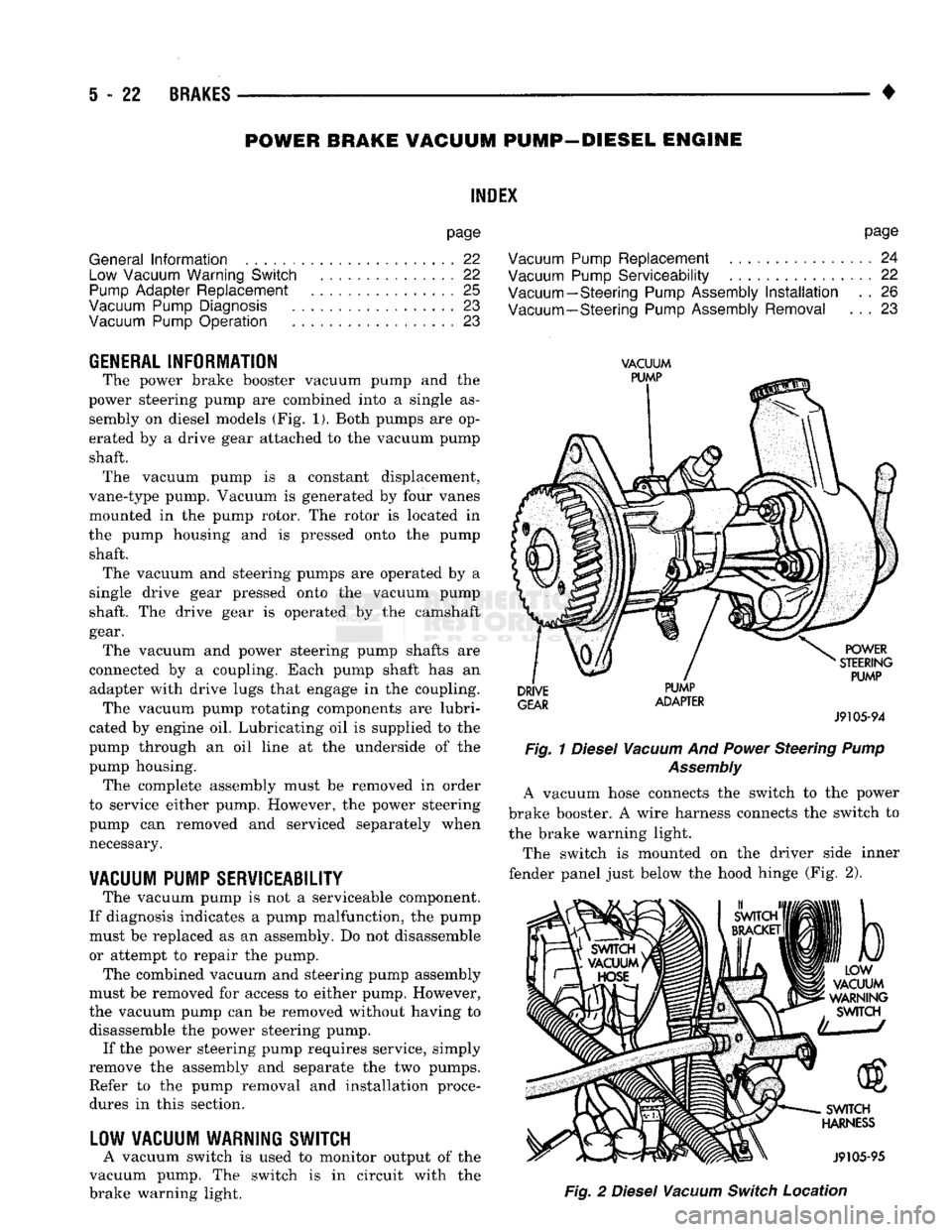
The power brake booster vacuum pump
and the
power steering pump
are
combined into
a
single
as
sembly
on
diesel models
(Fig. 1).
Both pumps
are op
erated
by a
drive gear attached
to the
vacuum pump shaft. The vacuum pump
is a
constant displacement,
vane-type pump. Vacuum
is
generated
by
four vanes
mounted
in the
pump rotor.
The
rotor
is
located
in
the pump housing
and is
pressed onto
the
pump shaft. The vacuum
and
steering pumps
are
operated
by a
single drive gear pressed onto
the
vacuum pump
shaft.
The
drive gear
is
operated
by the
camshaft
gear. The vacuum
and
power steering pump shafts
are
connected
by a
coupling. Each pump shaft
has an
adapter with drive lugs that engage
in the
coupling. The vacuum pump rotating components
are
lubri
cated
by
engine
oil.
Lubricating
oil is
supplied
to the
pump through
an oil
line
at the
underside
of the
pump housing. The complete assembly must
be
removed
in
order
to service either pump. However,
the
power steering
pump
can
removed
and
serviced separately when necessary.
VACUUM
PUMP
SERVICEABILITY
The vacuum pump
is not a
serviceable component.
If diagnosis indicates
a
pump malfunction,
the
pump must
be
replaced
as an
assembly.
Do not
disassemble
or attempt
to
repair
the
pump.
The combined vacuum
and
steering pump assembly
must
be
removed
for
access
to
either pump. However,
the vacuum pump
can be
removed without having
to
disassemble
the
power steering pump. If
the
power steering pump requires service, simply
remove
the
assembly
and
separate
the two
pumps. Refer
to the
pump removal
and
installation procedures
in
this section.
LOW
VACUUM
WARNING
SWITCH
A vacuum switch
is
used
to
monitor output
of the
vacuum pump.
The
switch
is in
circuit with
the
brake warning light.
VACUUM
PUMP
DRIVE
GEAR
PUMP
ADAPTER
POWER
STEERING
PUMP
J9105-94
Fig.
1
Diesel
Vacuum
And
Power
Steering
Pump
Assembly
A vacuum hose connects
the
switch
to the
power
brake booster.
A
wire harness connects
the
switch
to
the brake warning light.
The switch
is
mounted
on the
driver side inner
fender panel just below
the
hood hinge
(Fig. 2),
b
LOW
VACUUM
WARNING
SWITCH
SWITCH
HARNESS
J9105-95
Fig.
2
Diesel
Vacuum
Switch
Location
Page 210 of 1502
•
BRAKES
5 - 23
VACUUM PUMP OPERATION
Vacuum pump output is transmitted to the power
brake booster through a supply hose. The hose is con nected to an outlet port on the pump housing and to
the check valve in the power brake booster.
Pump output ranges from a minimum of 8.5 to 25
inches vacuum. The pump rotor and vanes are rotated by the pump
drive gear. The drive gear is operated by the cam
shaft gear. Booster vacuum level is monitored by a warning
switch (Fig. 2). The switch consists of a vacuum
chamber that measures vacuum level and a sensor in
circuit with the brake warning light. The vacuum chamber is connected to the booster
check valve by a vacuum supply hose. A wire har
ness connects the switch sensor to the brake warning
light. If booster vacuum falls below 8.5 inches for 8-10 seconds or more, the switch sensor completes
the circuit to the warning light causing it to illumi
nate.
VACUUM PUMP DIAGNOSIS
Vacuum pump diagnosis involves checking pump
output with a vacuum gauge. The low vacuum warn
ing switch can also be checked with a vacuum gauge.
Refer to the diagnosis procedure in this section. A standard vacuum gauge can be used to check
pump output when necessary. Simply disconnect the
pump supply hose and connect a vacuum gauge to
the outlet port for testing purposes. Vacuum should
hold steady in a range of approximately 8.5 to 25 inches at various engine speeds.
DIAGNOSING LOW VACUUM OUTPUT CONDITION A low booster vacuum condition or a faulty low
vacuum warning switch will cause the brake warn ing light to illuminate. If the light does go on and in
dicates the existence of a low vacuum condition,
check the vacuum pump, booster and warning switch
as follows:
(1) Check vacuum pump oil feed line. Verify that
line connections are secure and not leaking. If leak age is noted and pump is noisy, replace pump.
(2) Disconnect supply hose to booster. Connect vac
uum gauge to this hose and run engine at various
throttle openings. Output should range from 8.5 to 25 inches vacuum. If vacuum is consistently below
8.5 inches, problem is with vacuum hoses or pump
component. If output is within specified limits, con
tinue testing.
(3) Check booster operation as described in diagno
sis section. Replace check valve, vacuum hoses, or
booster if necessary. However, if booster operation is correct but warning light is still on, continue testing. (4) Disconnect vacuum hose at warning switch.
Plug hose and connect hand vacuum pump to switch. (5) Start and run engine.
(6) Apply 8.5 to 9 inches of vacuum to warning
switch and observe warning light. If light goes out,
switch vacuum hose is either loose or leaking. If
light remains on, leave engine running and continue
testing.
(7) Apply 20-25 inches vacuum to switch and ob
serve warning light operation. If light now goes out,
switch is at fault and should be replaced. If light re
mains on, continue testing.
(8) Reconnect vacuum hoses and replace original
warning switch with known good switch. Run engine and observe warning light operation. If light is now
off, old switch is faulty. If light remains on, problem
is in wiring between switch and warning light.
VACUUM-STEERING PUMP
ASSEMBLY
REMOVAL
(1) Disconnect battery negative cable.
(2) Position drain pan under power steering pump.
(3) Disconnect vacuum and steering pump hoses
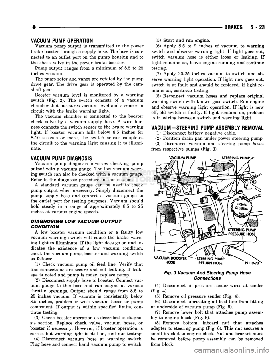
from respective pumps (Fig. 3).
Fig.
3
Vacuum
And Steering
Pump Hose
Connections
(4) Disconnect oil pressure sender wires at sender
(Fig. 4).
(5) Remove oil pressure sender (Fig. 4).
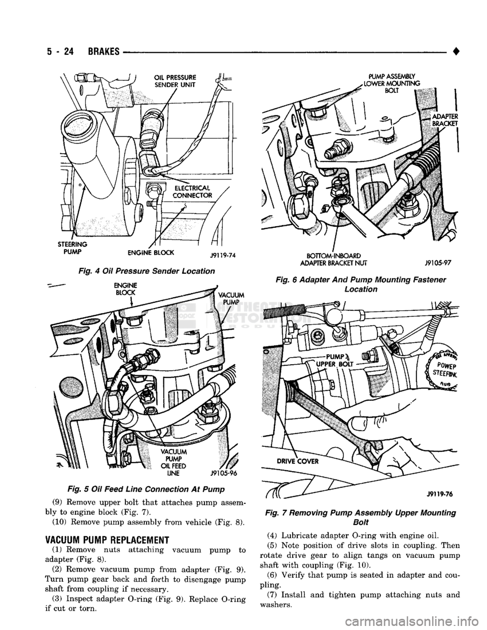
(6) Disconnect lubricating oil feed line from fitting
at underside of vacuum pump (Fig. 5).
(7) Remove lower bolt that attaches pump assem
bly to engine block (Fig. 6).
(8) Remove bottom, inboard nut that attaches
adapter to steering pump (Fig. 6). This nut secures a
small bracket to engine block. Nut and bracket must
be removed before pump assembly can be removed from block.
Page 211 of 1502
S
- 24
BRAKES
•
LINE
J9105-96
Fig. 5 Oil Feed Line Connection At Pump (9) Remove upper bolt that attaches pump assem
bly to engine block (Fig. 7).
(10) Remove pump assembly from vehicle (Fig. 8).
VACUUM PUMP REPLACEMENT
(1) Remove nuts attaching vacuum pump to
adapter (Fig. 8). (2) Remove vacuum pump from adapter (Fig. 9).
Turn pump gear back and forth to disengage pump shaft from coupling if necessary. (3) Inspect adapter O-ring (Fig. 9). Replace O-ring
if cut or torn.
PUMP ASSEMBLY
SOTTOM-INIOAiD
ADAPTER
BRACKET
NUT
J9105-97
Fig. 6 Adapter And
Pump
Mounting Fastener Location Fig. 7 Removing Pump Assembly Upper Mounting
Bolt
(4) Lubricate adapter O-ring with engine oil.
(5) Note position of drive slots in coupling. Then
rotate drive gear to align tangs on vacuum pump shaft with coupling (Fig. 10).
(6) Verify that pump is seated in adapter and cou
pling.
(7) Install and tighten pump attaching nuts and
washers.
Page 213 of 1502
5
- 26
BRAKES
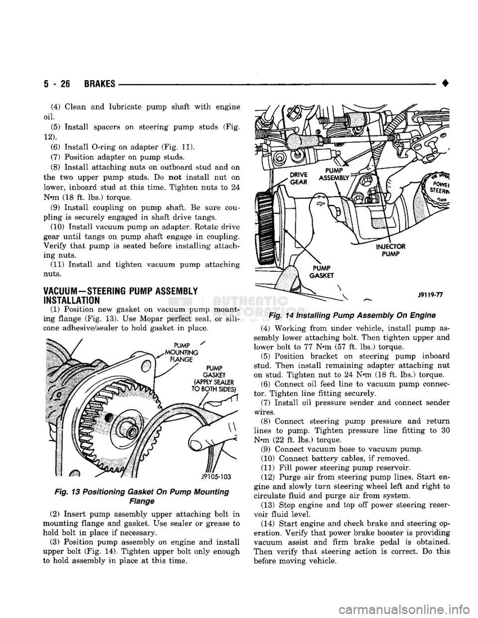
Fig. 13 Positioning Gasket On Pump Mounting
Flange
(2) Insert pump assembly upper attaching bolt in
mounting flange and gasket. Use sealer or grease to
hold bolt in place if necessary.
(3) Position pump assembly on engine and install
upper bolt (Fig. 14). Tighten upper bolt only enough
to hold assembly in place at this time. •
Fig. 14 Installing Pump Assembly On Engine (4) Working from under vehicle, install pump as
sembly lower attaching bolt. Then tighten upper and
lower bolt to 77 N»m (57 ft. lbs.) torque. (5) Position bracket on steering pump inboard
stud. Then install remaining adapter attaching nut
on stud. Tighten nut to 24 N«m (18 ft. lbs.) torque.
(6) Connect oil feed line to vacuum pump connec
tor. Tighten line fitting securely.
(7) Install oil pressure sender and connect sender
wires.
(8) Connect steering pump pressure and return
lines to pump. Tighten pressure line fitting to 30
N-m (22 ft. lbs.) torque.
(9) Connect vacuum hose to vacuum pump.
(10) Connect battery cables, if removed.
(11) Fill power steering pump reservoir.
(12) Purge air from steering pump lines. Start en
gine and slowly turn steering wheel left and right to circulate fluid and purge air from system.
(13) Stop engine and top off power steering reser
voir fluid level.
(14) Start engine and check brake and steering op
eration. Verify that power brake booster is providing
vacuum assist and firm brake pedal is obtained.
Then verify that steering action is correct. Do this
before moving vehicle.
(4) Clean and lubricate pump shaft with engine
oil.
(5) Install spacers on steering pump studs (Fig.
12).
(6) Install O-ring on adapter (Fig. 11).
(7) Position adapter on pump studs.
(8) Install attaching nuts on outboard stud and on
the two upper pump studs. Do not install nut on
lower, inboard stud at this time. Tighten nuts to 24
N-m (18 ft. lbs.) torque. (9) Install coupling on pump shaft. Be sure cou
pling is securely engaged in shaft drive tangs. (10) Install vacuum pump on adapter. Rotate drive
gear until tangs on pump shaft engage in coupling.
Verify that pump is seated before installing attach
ing nuts. (11) Install and tighten vacuum pump attaching
nuts.
VACUUM-STEERING PUMP ASSEMBLY INSTALLATION
(1) Position new gasket on vacuum pump mount
ing flange (Fig. 13). Use Mopar perfect seal, or sili
cone adhesive/sealer to hold gasket in place.
Page 255 of 1502
6
- 2
CLUTCH
•
CLUTCH DIAGNOSIS
INDEX
page
Clutch Problem
Causes
, 2
General
Diagnosis
Information
2
GENERAL
DIAGNOSIS INFORMATION
Unless the cause of a clutch problem is obvious, a
road test and component inspection will be required
for accurate diagnosis. A road test will help determine the type of fault
while component inspection will identify the problem component. During a road test, drive the vehicle at normal
speeds. Shift the transmission through all gear
ranges and observe clutch action. If chatter, grab, slip, or improper release is experi
enced, remove and inspect the clutch components.
However, if the problem is noise or hard shifting,
further diagnosis is needed. The transmission or an
other driveline component may actually be at fault. Careful observation during a road test will help
narrow the problem area.
CLUTCH PROBLEM
CAUSES
CONTAMINATION Fluid contamination is one of the more common
causes of clutch malfunctions. Oil, water, or clutch
fluid on the clutch contact surfaces will result in
faulty operation. The usual result is chatter, slip, or
grab.
During inspection, note if any components are con
taminated with oil, hydraulic fluid, or water/road splash.
Oil contamination indicates a leak at either the
rear main seal or transmission input shaft.
Oil leakage produces a residue of oil on the hous
ing interior and on the clutch cover and flywheel.
Heat buildup caused by slippage between the cover,
disc and flywheel, can sometimes bake the oil residue
onto the components. The glaze-like residue ranges
in color from amber to black.
Road splash contamination means dirt and water
are entering the clutch housing due to loose bolts,
housing cracks, vent openings, or through the slave
cylinder opening. Driving through deep water pud
dles can force water/road splash into the housing
through such openings.
An additional problem caused by water contamina
tion and especially by steam cleaning, involves
clutch disc sticking and poor release. Water and steam vapors can be absorbed by the
clutch facing material. If the vehicle sits idle for long
page
Inspection
and
Diagnosis
Charts 5
periods after water contamination, the force exerted
by the pressure plate may cause the disc to bond it self to the flywheel or pressure plate.
Frequently, the only remedy for the above condi
tion is component replacement. To avoid this prob
lem, a vehicle should be driven as soon as possible to
heat and dry the clutch components.
Clutch fluid leaks are from a loose or damaged
slave cylinder line or connection. However, clutch
fluid leaks will usually be noted and corrected before severe contamination occurs.
CLUTCH MISALIGNMENT
Clutch components must be in proper alignment
with the crankshaft and transmission input shaft.
Misalignment caused by excessive runout or warpage of any clutch component will cause grab, chatter and improper clutch release.
Flywheel
Runout
Common causes of runout are heat warping, im
proper machining, mounting the flywheel on a dirty crankshaft flange, incorrect bolt tightening, or im
proper seating on the crankshaft flange shoulder.
Very light scratches or surface roughness on the
flywheel face can be cleaned up by scuff sanding with 180 grit emery cloth. However, if the surface is
warped or severely scored, replace the flywheel.
Do not machine the flywheel. The flywheel
face is manufactured with a unique surface con
tour. Machining would negate this feature and could result in unsatisfactory operation.
Clean the crankshaft flange before mounting the
flywheel. Dirt and grease on the flange surface may cock the flywheel causing runout.
Use new bolts when remounting a flywheel and se
cure the bolts with Mopar Lock And Seal, or Loctite
242.
Tighten flywheel bolts to specified torque only.
Overtightening could distort the flywheel hub caus
ing runout.
Clutch
Cover
And Disc
Runout
Check the clutch disc before installation. Axial
(face) runout of a new disc should not exceed 0.5 mm
(0.020 in.). Measure runout about 6 mm (1/4 in.)
from the outer edge of the disc facing. Obtain an other disc if runout is excessive.
Page 259 of 1502
6 - 6
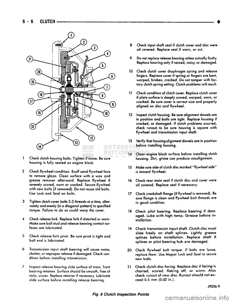
CLUTCH
1
Check
clutch
housing bolts.
Tighten
if loose. Be sure
housing
is
fully
seated on engine block.
2 Check
flywheel
condition.
Scuff sand
flywheel
face
to remove glaze. Clean surface
with
a wax and
grease
remover afterward. Replace
flywheel
if
severely scored, worn or cracked. Secure
flywheel
with
new bolts (if removed). Do not reuse old bolts.
Use
Lock and Seal on bolts.
3
Tighten clutch cover bolts 2-3 threads at a
time,
alter
nately and evenly (in a diagonal
pattern)
to specified
torque. Failure to do so could warp the cover.
4 Check release fork. Replace fork if distorted or worn. Make sure ball stud and release bearing contact sur
faces
are lubricated.
5
Check release fork pivot. Be sure pivot is tight and ball end is lubricated.
6 Transmission input
shaft
bearing
will
cause noise,
chatter,
or improper release if
damaged.
Check
con
dition before installing transmission.
7 Inspect release bearing slide surface of trans,
front
bearing
retainer.
Surface should be smooth,
free
of
nicks,
scores.
Replace
retainer
if
necessary.
Lubricate slide surface before installing release bearing. 8 Check input shaft seal if clutch cover and
disc
were
oil covered. Replace seal if worn, or cut.
9 Do not replace release bearing
unless
actually
faulty.
Replace bearing only if seized, noisy, or damaged.
10 Check clutch cover diaphragm spring and release
fingers.
Replace cover if spring or fingers are bent, warped, broken, cracked. Do not tamper
with
fac
tory
clutch spring setting. Clutch problems
will
result.
11 Check condition of clutch cover. Replace clutch cover if
plate
surface is deeply scored, warped, worn, or
cracked. Be sure cover is correct size and properly
aligned on
disc
and flywheel.
12 Inspect clutch
housing.
Be sure alignment dowels are in position and bolts are tight. Replace housing if
cracked, or damaged. If clutch problems ocurred,
check runout, to be sure housing is square
with
flywheel
and transmission input shaft.
13
Verify
that
housing
alignment dowels are in position before installing
housing.
14 Clean engine block surface before installing clutch
housing.
Dirt, grime can produce misalignment.
15 Make sure side of clutch
disc
marked
"flywheel
side"
is
toward flywheel.
16 Check
rear
main seal if clutch
disc
and cover
were
oil covered. Replace seal if necessary.
17 Check crankshaft flange (if
flywheel
is removed). Be sure flange is clean and
flywheel
bolt threads are
in
good
condition.
18 Check pilot bearing. Replace bearing if dam
aged.
Lube
with
high temp. Grease before in
stallation.
19 Check transmission input shaft. Clutch
disc
must slide
freely
on shaft splines. Lightly grease
splines
before installation. Replace shaft if
splines
or pilot bearing hub are damaged.
20 Check
flywheel
bolt torque. If bolts are loose, replace them. Use Mopar Lock and Seal to secure
new bolts.
21 Check clutch
disc
facing. Replace
disc
if facing is charred, scored, flaking off, or worn.
Also
check runout of new
disc.
Runout should not ex
ceed 0.5 mm (0.02 in.).
J9206-9
Fig. 8 Clutch Inspection Points