dome DODGE TRUCK 1993 Service Repair Manual
[x] Cancel search | Manufacturer: DODGE, Model Year: 1993, Model line: TRUCK, Model: DODGE TRUCK 1993Pages: 1502, PDF Size: 80.97 MB
Page 47 of 1502
0
- 28
LUBRICATION
AND
MAINTENANCE
•
CHASSIS AND BODY
page
Body
Component Mechanisms
32
Front
Suspension
Ball
Joints
28
Front
Wheel Bearings
29
Headlamps
32
Lower
and
Upper Suspension
Arm
Bushings
.... 30
Manual
Steering Gear
28
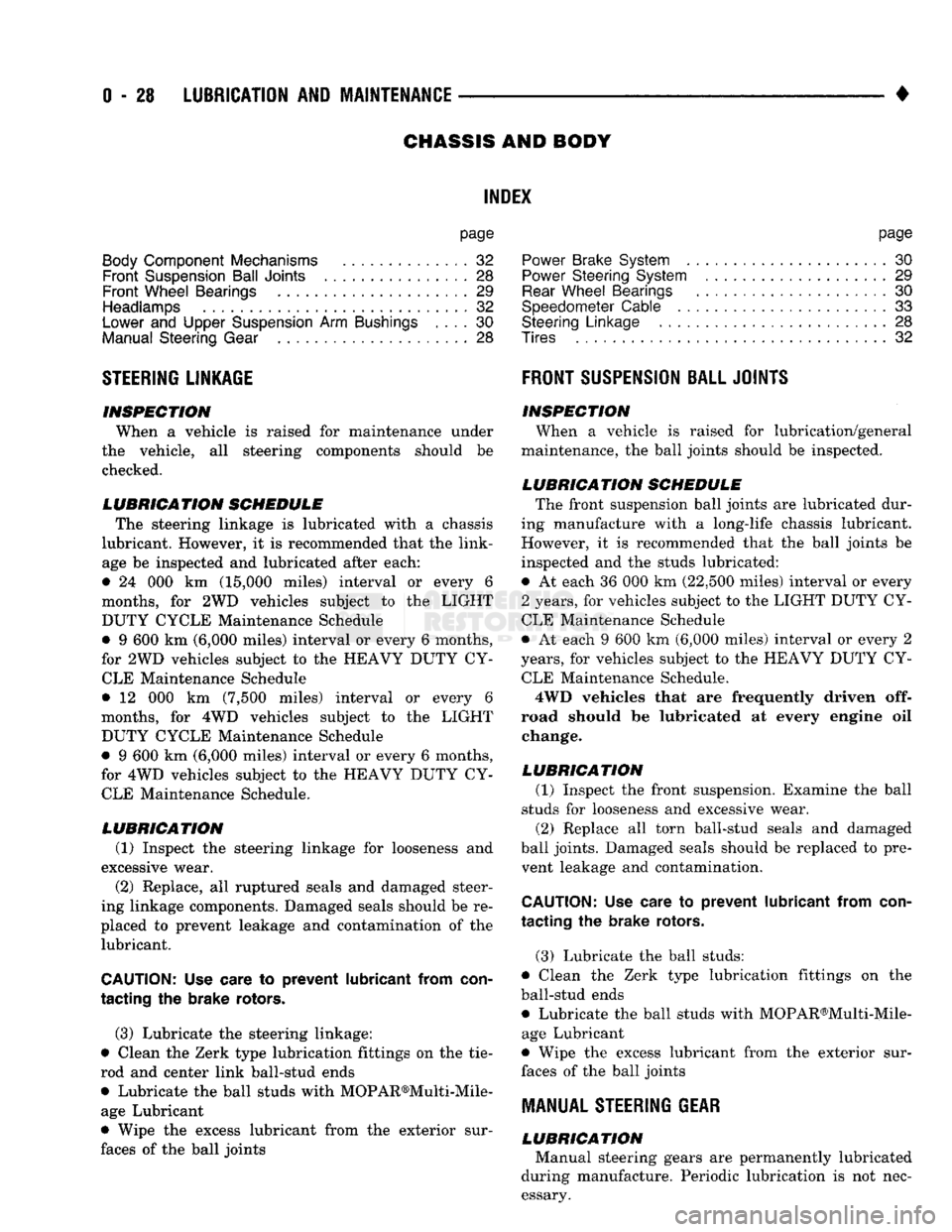
STEERING
LINKAGE
INSPECTION When
a
vehicle
is
raised
for
maintenance under
the vehicle,
all
steering components should
be
checked.
LUBRICATION SCHEDULE The steering linkage
is
lubricated with
a
chassis
lubricant. However,
it is
recommended that
the
link
age
be
inspected
and
lubricated after each:
•
24 000 km
(15,000 miles) interval
or
every
6
months,
for 2WD
vehicles subject
to the
LIGHT
DUTY CYCLE Maintenance Schedule
•
9 600 km
(6,000 miles) interval
or
every
6
months,
for
2WD
vehicles subject
to the
HEAVY DUTY
CY
CLE Maintenance Schedule
•
12 000 km
(7,500 miles) interval
or
every
6
months,
for 4WD
vehicles subject
to the
LIGHT DUTY CYCLE Maintenance Schedule
•
9 600 km
(6,000 miles) interval
or
every
6
months,
for
4WD
vehicles subject
to the
HEAVY DUTY
CY
CLE Maintenance Schedule.
LUBRICATION (1) Inspect
the
steering linkage
for
looseness
and
excessive wear. (2) Replace,
all
ruptured seals
and
damaged steer
ing linkage components. Damaged seals should
be re
placed
to
prevent leakage
and
contamination
of the
lubricant.
CAUTION:
Use
care
to
prevent lubricant from
con
tacting
the
brake rotors.
(3) Lubricate
the
steering linkage:
• Clean
the
Zerk type lubrication fittings
on the tie-
rod
and
center link ball-stud ends
• Lubricate
the
ball studs with MOPAR®Multi-Mile- age Lubricant
• Wipe
the
excess lubricant from
the
exterior sur
faces
of the
ball joints
page
Power
Brake System
30
Power
Steering System
. . 29
Rear
Wheel Bearings
30
Speedometer Cable
33
Steering Linkage
28
Tires
32
FRONT
SUSPENSION
BALL JOINTS
INSPECTION When
a
vehicle
is
raised
for
lubrication/general
maintenance,
the
ball joints should
be
inspected.
LUBRICATION SCHEDULE The front suspension ball joints
are
lubricated dur
ing manufacture with
a
long-life chassis lubricant.
However,
it is
recommended that
the
ball joints
be
inspected
and the
studs lubricated:
•
At
each
36 000 km
(22,500 miles) interval
or
every
2 years,
for
vehicles subject
to the
LIGHT DUTY
CY
CLE Maintenance Schedule
•
At
each
9 600 km
(6,000 miles) interval
or
every
2
years,
for
vehicles subject
to the
HEAVY DUTY
CY
CLE Maintenance Schedule.
4WD vehicles that
are
frequently driven
off-
road should
be
lubricated
at
every engine
oil
change.
LUBRICATION (1) Inspect
the
front suspension. Examine
the
ball
studs
for
looseness
and
excessive wear. (2) Replace
all
torn ball-stud seals
and
damaged
ball joints. Damaged seals should
be
replaced
to
pre vent leakage
and
contamination.
CAUTION:
Use
care
to
prevent lubricant from
con
tacting
the
brake rotors.
(3) Lubricate
the
ball studs:
• Clean
the
Zerk type lubrication fittings
on the
ball-stud ends
• Lubricate
the
ball studs with MOPAR®Multi-Mile-age Lubricant
• Wipe
the
excess lubricant from
the
exterior sur
faces
of the
ball joints
MANUAL
STEERING
GEAR
LUBRICATION Manual steering gears
are
permanently lubricated
during manufacture. Periodic lubrication
is not
nec
essary.
Page 52 of 1502
•
LUBRICATION
AND
MAINTENANCE
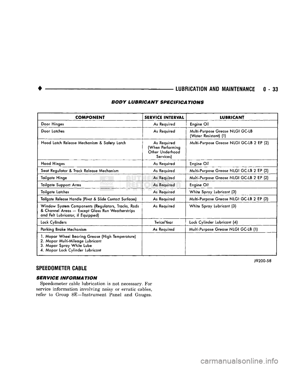
0 - 33 BODY LUBRICANT SPECIFICATIONS
COMPONENT
SERVICE
INTERVAL
LUBRICANT
Door
Hinges
As
Required
Engine
Oil
Door
Latches
As
Required Multi-Purpose Grease
NLGI
GC-LB
(Water
Resistant)
(1)
Hood
Latch Release Mechanism
&
Safety Latch
As
Required
(When Performing Other Underhood Services) Multi-Purpose Grease
NLGI
GC-LB
2
EP
(2)
Hood
Hinges
As
Required
Engine
Oil
Seat Regulator
&
Track Release Mechanism
As
Required Multi-Purpose Grease
NLGI
GC-LB
2
EP
(2)
Tailgate Hinge
As
Required Multi-Purpose Grease
NLGI
GC-LB
2
EP
(2)
Tailgate Support Arms
As
Required
Engine
Oil
Tailgate Latches
As
Required
White
Spray Lubricant
(3)
Tailgate Release Handle (Pivot & Slide Contact Surfaces)
As
Required Multi-Purpose Grease
NLGI
GC-LB
2
EP
(2)
Window System Components (Regulators, Tracks,
Rods
&
Channel Areas — Except
Glass
Run Weatherstrips
and
Felt
Lubricator,
if
Equipped)
As
Required
White
Spray Lubricant
(3)
Lock
Cylinders Twice/Year
Lock
Cylinder Lubricant
(4)
Parking Brake Mechanism
As
Required Multi-Purpose Grease
NLGI
GC-LB
(1)
1.
Mopar
Wheel
Bearing Grease (High
Temperature)
2. Mopar Multi-Mileage Lubricant 3. Mopar Spray
White
Lube
4. Mopar Lock Cylinder Lubricant
J9200-58
SPEEDOMETER
CABLE
SERVICE INFORMATION Speedometer cable lubrication is not necessary. For
service information involving noisy or erratic cables,
refer to Group 8E—Instrument Panel and Gauges.
Page 331 of 1502
8A
- 10
ELECTRICAL
•
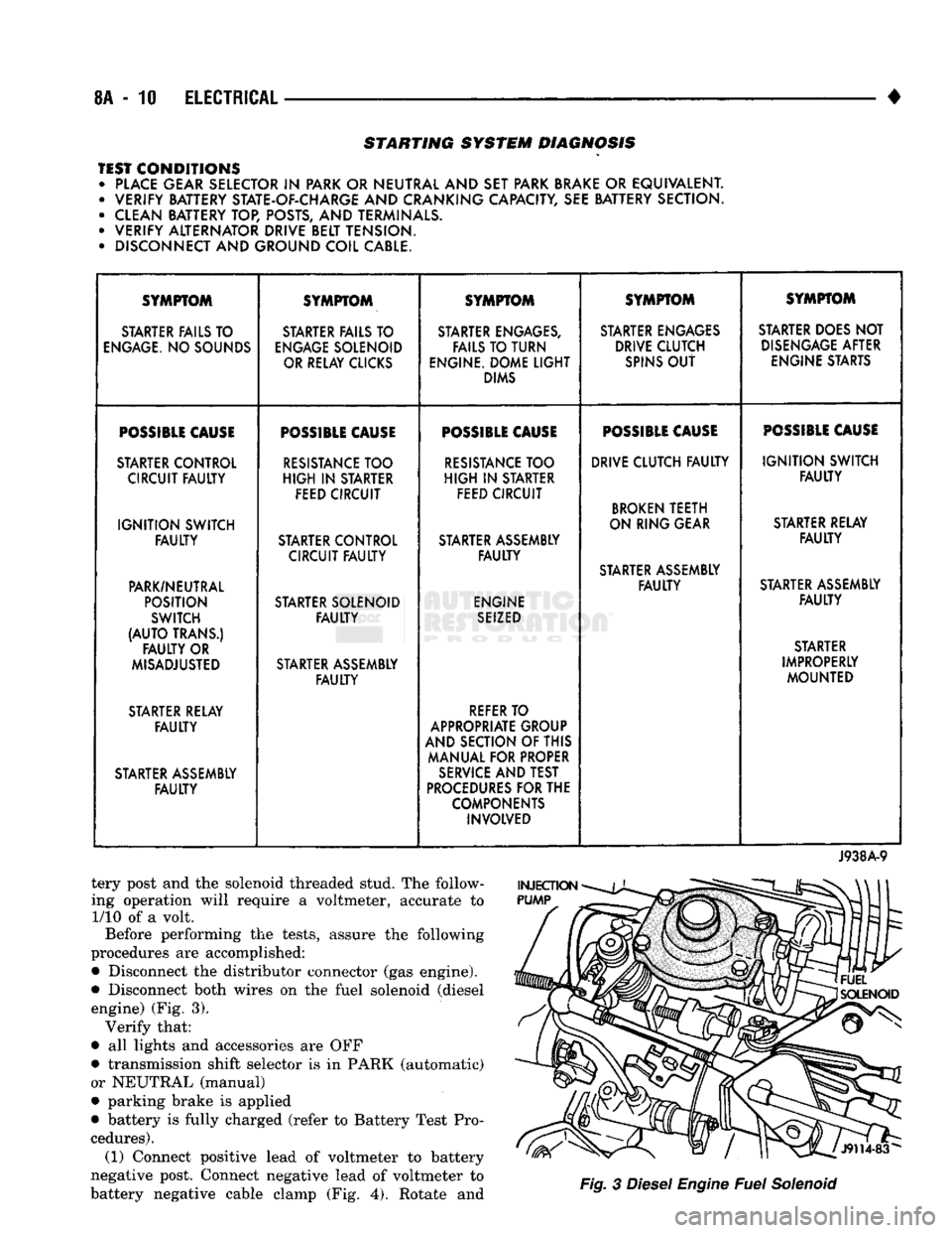
STARTING SYSTEM DIAGNOSIS
TEST CONDITIONS • PLACE GEAR SELECTOR
IN
PARK OR NEUTRAL AND SET PARK BRAKE
OR
EQUIVALENT. • VERIFY BATTERY STATE-OF-CHARGE AND CRANKING CAPACITY, SEE BATTERY SECTION.
• CLEAN BATTERY TOP, POSTS, AND TERMINALS.
• VERIFY ALTERNATOR DRIVE BELT TENSION.
• DISCONNECT AND GROUND COIL CABLE. SYMPTOM
SYMPTOM SYMPTOM SYMPTOM SYMPTOM
STARTER FAILS TO STARTER FAILS TO STARTER ENGAGES, STARTER ENGAGES STARTER DOES NOT
ENGAGE.
NO SOUNDS
ENGAGE
SOLENOID FAILS TO TURN DRIVE CLUTCH
DISENGAGE
AFTER
OR RELAY CLICKS ENGINE. DOME
LIGHT
SPINS
OUT
ENGINE STARTS
DIMS
POSSIBLE
CAUSE
POSSIBLE
CAUSE
POSSIBLE
CAUSE
POSSIBLE
CAUSE
POSSIBLE
CAUSE
STARTER CONTROL
RESISTANCE
TOO
RESISTANCE
TOO DRIVE CLUTCH
FAULTY
IGNITION
SWITCH
CIRCUIT
FAULTY
HIGH
IN
STARTER
HIGH
IN
STARTER
FAULTY
FEED CIRCUIT FEED CIRCUIT
BROKEN
TEETH
IGNITION
SWITCH ON RING GEAR
STARTER RELAY
FAULTY
STARTER CONTROL STARTER ASSEMBLY
FAULTY
CIRCUIT
FAULTY FAULTY
STARTER ASSEMBLY
PARK/NEUTRAL
FAULTY
STARTER ASSEMBLY
POSITION STARTER SOLENOID ENGINE
FAULTY
SWITCH
FAULTY
SEIZED
(AUTO
TRANS.) STARTER
FAULTY
OR STARTER
MISADJUSTED STARTER ASSEMBLY IMPROPERLY
FAULTY
MOUNTED
STARTER RELAY
REFER
TO
FAULTY
APPROPRIATE GROUP
AND SECTION OF THIS
MANUAL FOR PROPER
STARTER ASSEMBLY
SERVICE
AND TEST
FAULTY
PROCEDURES
FOR THE
COMPONENTS INVOLVED
J938A-9
tery post and the solenoid threaded stud. The follow
ing operation will require a voltmeter, accurate to 1/10 of a volt.
Before performing the tests, assure the following
procedures are accomplished:
•
Disconnect the distributor connector (gas engine).
•
Disconnect both wires on the fuel solenoid (diesel engine) (Fig. 3). Verify that:
•
all lights and accessories are OFF
•
transmission shift selector is in PARK (automatic)
or NEUTRAL (manual)
•
parking brake is applied
•
battery is fully charged (refer to Battery Test Pro
cedures). (1) Connect positive lead of voltmeter to battery
negative post. Connect negative lead of voltmeter to
battery negative cable clamp (Fig. 4). Rotate and
Fig.
3
Diesel
Engine
Fuel
Solenoid
Page 382 of 1502

• • ^ ^ ^ INSTRUMENT PANEL AND GAUGES 8E - 1
CONTENTS
page
CLUSTER AND GAUGE SERVICE PROCEDURES . 12
CLUSTER AND GAUGE TEST PROCEDURES .. i
GENERAL INFORMATION . 1
page
MESSAGE CENTER-DIESEL ENGINE ........ 4
MESSAGE CENTER-GAS ENGINE .......... 3
SWITCH
AND PANEL COMPONENT SERVICE . 16
GENERAL
INFORMATION
INDEX
page
Generator
Indicating
System
2
Distance
Sensor
2
Electronic
Digital
Clock
3
Fuel
Level
Indicating
System
1
page
Malfunction
Indicator
(Check
Engine)
3
Oil
Pressure
Warning
Lamp
................. 2
Speedometer/Odometer
System
2
Temperature
and Oil
Indicating
System
......... 2
D-body trucks have an instrument cluster which
includes gauges for fuel level, coolant temperature,
oil pressure, and charging system voltage (Fig. 1).
When the ignition switch is in the OFF position all
the gauges will show a reading except the voltage gauge. However, the readings are only accurate
when the ignition switch is in the ON position.
The cluster also includes warning lamps for:
• seat belt warning
• low oil pressure
• high beam
• left and right turn signals
• check engine. J908E-66
Fig.
11nstrument
Cluster
FUEL LEVEL INDICATING SYSTEM (FIG. 2)
A hinged float arm in the fuel tank raises or lowers
depending on the fuel level. The float arm contacts a
variable resistor in the gauge sending unit. This pro
vides a change of resistance in the fuel gauge circuit
with any up or down movement of the float. This sender
resistance is shown as fuel level on the gauge. Resistance is greatest when the fuel level in the
tank is low and the float arm drops. With high resis
tance current flow is low and consequently positions
the instrument panel gauge pointer to low.
Resistance in the circuit is at a minimum when the
tank is full and the float arm is raised. With resis
tance at a minimum, current flow is high registering
full on the instrument panel gauge.
12
VOLTS
TO
GAUGE
IP
FUEL
TANK
SENDING
UNIT
FLOAT
SENDING
UNIT
1:
1
j
^
fCONNECTOR
!g|yj-»—
FUEL
GAUGE
FUEL
TANK
J098E-47
Fig.
2
Fuel
Level
Indicating
System
INSTRUMENT PANEL AND GAUGES
Page 383 of 1502
8E
- 2
INSTRUMENT PANEL
AND
GAUGES
•
TEMPERATURE AND
OIL
INDICATING SYSTEM
(FIG.
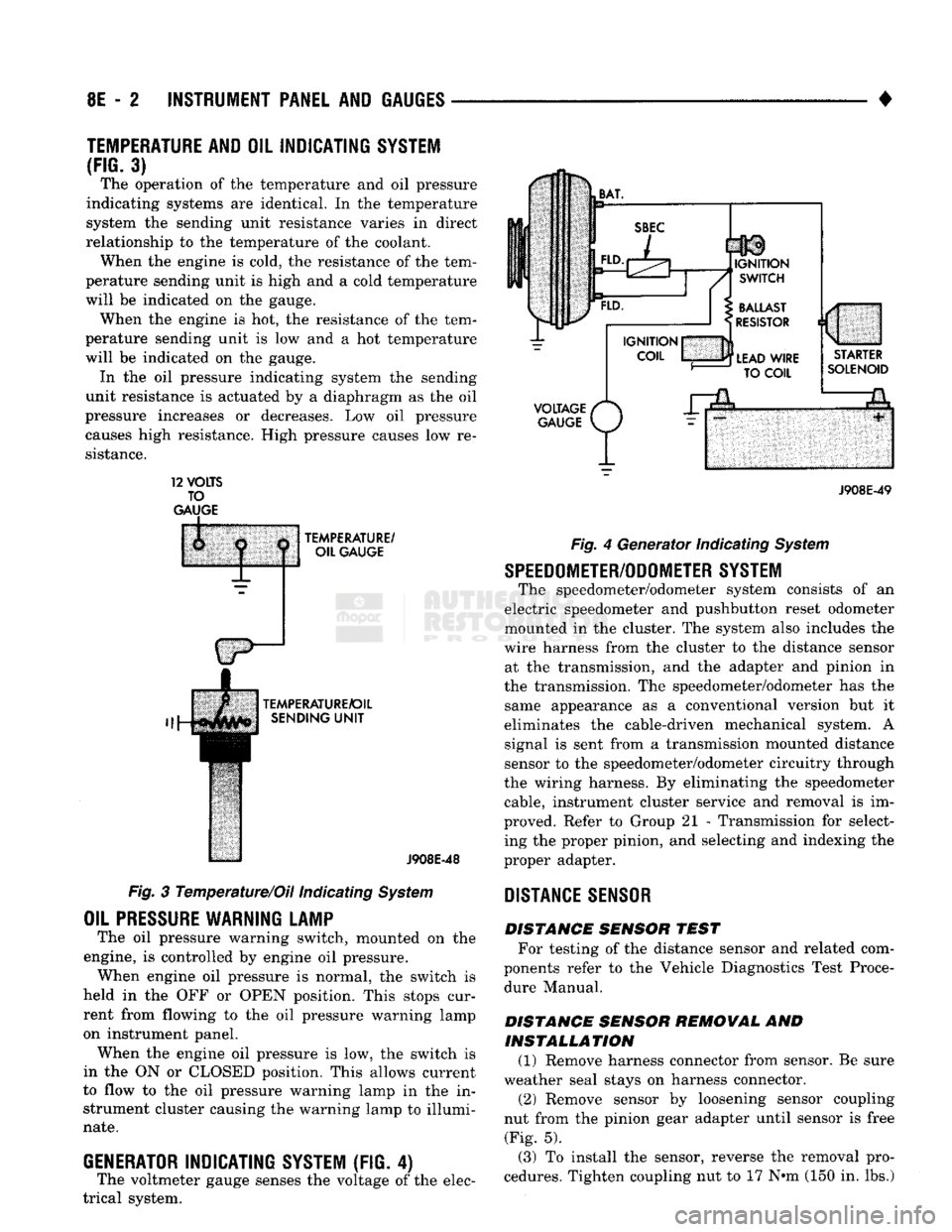
3) The operation of the temperature and oil pressure
indicating systems are identical. In the temperature
system the sending unit resistance varies in direct
relationship to the temperature of the coolant. When the engine is cold, the resistance of the tem
perature sending unit is high and a cold temperature
will be indicated on the gauge. When the engine is hot, the resistance of the tem
perature sending unit is low and a hot temperature
will be indicated on the gauge. In the oil pressure indicating system the sending
unit resistance is actuated by a diaphragm as the oil
pressure increases or decreases. Low oil pressure causes high resistance. High pressure causes low re
sistance. 12
VOLTS
TO
GAUGE
TEMPERATURE/
OIL GAUGE
TEMPERATURE/OIL SENDING
UNIT
J908E-48
Fig. 3 Temperature/Oil indicating System
OIL
PRESSURE
WARNING LAMP
The oil pressure warning switch, mounted on the
engine, is controlled by engine oil pressure. When engine oil pressure is normal, the switch is
held in the OFF or OPEN position. This stops cur
rent from flowing to the oil pressure warning lamp
on instrument panel. When the engine oil pressure is low, the switch is
in the ON or CLOSED position. This allows current
to flow to the oil pressure warning lamp in the in strument cluster causing the warning lamp to illumi
nate.
GENERATOR
INDICATING
SYSTEM
(FIG. 4)
The voltmeter gauge senses the voltage of the elec
trical system.
VOLTAGE
/*
GAUGE
P/
J908E-49 Fig. 4 Generator Indicating System
SPEEDOMETER/ODOMETER SYSTEM
The speedometer/odometer system consists of an
electric speedometer and pushbutton reset odometer
mounted in the cluster. The system also includes the
wire harness from the cluster to the distance sensor at the transmission, and the adapter and pinion in
the transmission. The speedometer/odometer has the same appearance as a conventional version but it
eliminates the cable-driven mechanical system. A signal is sent from a transmission mounted distance
sensor to the speedometer/odometer circuitry through
the wiring harness. By eliminating the speedometer cable, instrument cluster service and removal is im
proved. Refer to Group 21 - Transmission for select ing the proper pinion, and selecting and indexing the
proper adapter.
DISTANCE
SENSOR
DISTANCE SENSOR TEST For testing of the distance sensor and related com
ponents refer to the Vehicle Diagnostics Test Proce dure Manual.
DISTANCE SENSOR REMOVAL AND INSTALLATION (1) Remove harness connector from sensor. Be sure
weather seal stays on harness connector. (2) Remove sensor by loosening sensor coupling
nut from the pinion gear adapter until sensor is free (Fig. 5).
(3) To install the sensor, reverse the removal pro
cedures. Tighten coupling nut to 17 N»m (150 in. lbs.)
Page 386 of 1502
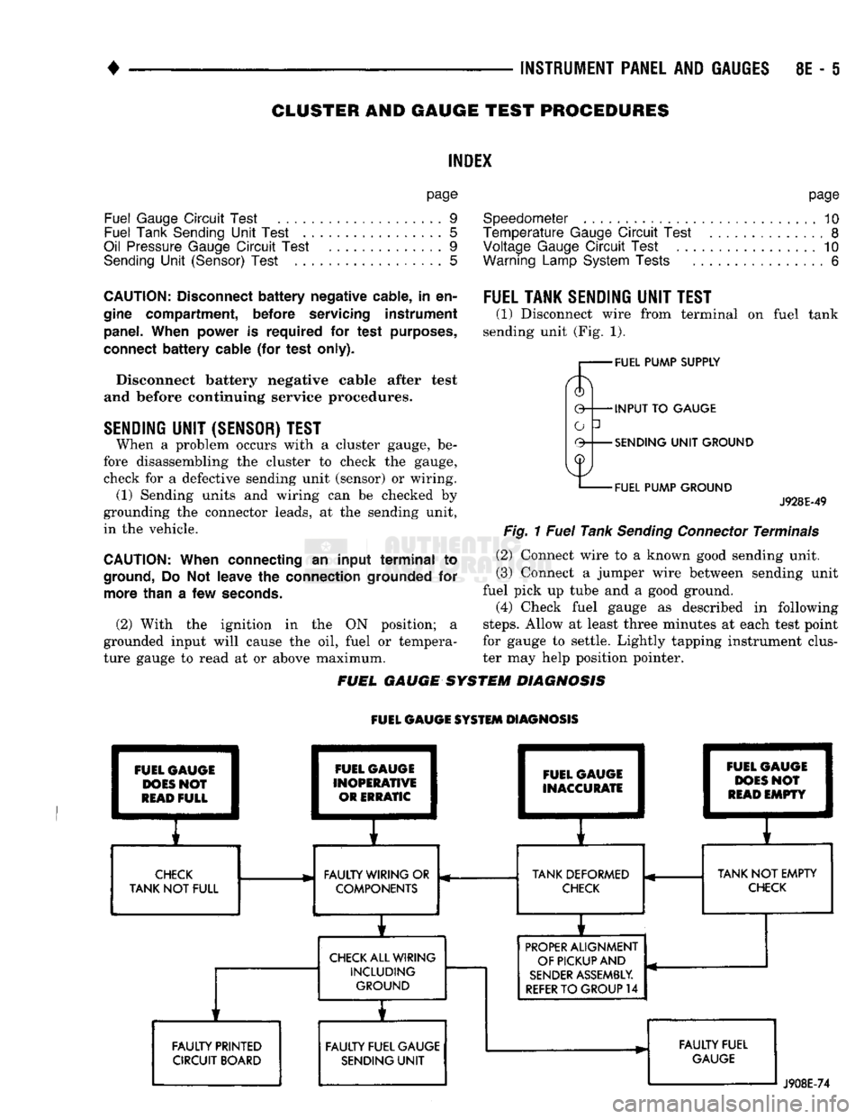
•
INSTRUMENT PANEL
AND
GAUGES
8E - 5
CLUSTER
AND
GAUGE TEST
PROCEDURES
INDEX
page
Fuel Gauge
Circuit
Test
9
Fuel Tank Sending
Unit
Test
5
Oil Pressure Gauge
Circuit
Test
..............
9
Sending
Unit
(Sensor) Test
5
page
Speedometer
10
Temperature
Gauge
Circuit
Test
8
Voltage Gauge
Circuit
Test
10
Warning Lamp System Tests
6
CAUTION:
Disconnect
battery
negative cable,
in
en
gine compartment, before servicing instrument panel. When power
is
required
for
test purposes,
connect
battery
cable
(for
test only).
Disconnect battery negative cable after test
and before continuing service procedures.
SENDING
UNIT
(SENSOR) TEST
When
a
problem occurs with
a
cluster gauge,
be
fore disassembling
the
cluster
to
check
the
gauge, check
for a
defective sending unit (sensor)
or
wiring.
(1) Sending units
and
wiring
can be
checked
by
grounding
the
connector leads,
at the
sending unit,
in
the
vehicle.
CAUTION:
When connecting
an
input
terminal
to
ground,
Do Not
leave
the
connection grounded
for
more than
a
few
seconds.
(2) With
the
ignition
in the ON
position;
a
grounded input will cause
the oil,
fuel
or
tempera
ture gauge
to
read
at or
above maximum.
FUEL TANK SENDING
UNIT
TEST
(1) Disconnect wire from terminal
on
fuel tank
sending unit (Fig.
1).
FUEL PUMP SUPPLY
INPUT
TO
GAUGE
SENDING
UNIT
GROUND
FUEL PUMP GROUND
J928E-49
Fig.
1
Fuel
Tank
Sending
Connector
Terminals
(2) Connect wire
to a
known good sending unit.
(3) Connect
a
jumper wire between sending unit
fuel pick
up
tube
and a
good ground.
(4) Check fuel gauge
as
described
in
following
steps.
Allow
at
least three minutes
at
each test point
for gauge
to
settle. Lightly tapping instrument clus
ter
may
help position pointer.
FUEL GAUGE SYSTEM DIAGNOSIS
FUEL GAUGE SYSTEM DIAGNOSIS FUEL GAUGE
DOES
NOT
READ
FULL FAULTY PRINTED
CIRCUIT BOARD FUEL GAUGE
INOPERATIVE OR ERRATIC FUEL GAUGE
INACCURATE
E
1
I
CHECK
FAULTY WIRING
OR
TANK DEFORMED
TANK
NOT
FULL COMPONENTS
CHECK
CHECK
ALL WIRING INCLUDING GROUND
i
FAULTY FUEL GAUGE SENDING
UNIT
i 1
FUEL
C
1
DOES
1
READ
1
pAUGE
I
>N0?
1
EMPTY
1
r
TANK
NOT
EMPTY
CHECK
PROPER
ALIGNMENT
OF PICKUP AND
SENDER
ASSEMBLY.
REFER
TO
GROUP
14
FAULTY FUEL
GAUGE
J908E-74
Page 391 of 1502

8E
- 10
INSTRUMENT
PANEL
AND
GAUGES
GROUND
OIL
PRESSURE
SENSOR
INPUT
J908E-70
Fig.
10 Oil Pressure
Sending
Unit—Gas Engine
STEERING
PUMP
ENGINE
BLOCK
J9119-74
Fig.
11 Oil Pressure
Sending
Unit—Diesel Engine
SENDING
UNIT
(GAUGE)
SWITCH
(LIGHT)
898E-2
Fig.
12 Combination Oil Unit Terminals
VOLTAGE
GAUGE
CIRCUIT
TEST
(1) Remove voltage gauge. Refer to Gauge Replace
ment.
Fig.
13 Oil Pressure
Gauge
Pins
r— FUEL
PUMP
SUPPLY
0 INPUT TO
GAUGE
-SENDING
UNIT
GROUND
-FUEL
PUMP
GROUND
J928E-49
Fig.
14 Fuel Tank
Sending
Connector Terminals
FUEL
GAUGE
INPUT
^
GROUND
y
J908E-71
Fig.
15 Fuel
Gauge
Pins
(2) With the ignition switch in the ON position,
check for battery voltage across the B+ pin and the Ground pin (Fig. 16).
The instrument panel voltmeter indicates elec
trical system battery voltage.
SPEEDOMETER
(1) Remove speedometer assembly. Refer to Gauge
Replacement.
Page 392 of 1502

•
Fig.
16
Voltmeter
Pins
(2) Check for continuity in the wire between the
distance sensor connector and the speedometer (dis
tance sensor input pin) (Fig. 17).
(3) With the ignition switch in the ON position,
check for battery voltage across the B + pin and the Ground pin. —
INSTRUMENT PANEL
AND
GAUGES
8E - 11
Fig.
17 Speedometer
Pins
(4) Perform distance sensor test. Refer to General
Information - Distance Sensor in this section.
(5)
If all previous tests prove good, replace speed
ometer.
Page 393 of 1502

8E
- 12
INSTRUMENT PANEL
AND
GAUGES
•
CLUSTER AND GAUGE
SERVICE
PROCEDURES
INDEX
page
Cluster Bezel
12
Cluster
Mask
and
Lens
12
Fuel Gauge
13
Instrument
Cluster Assembly
12
Lamp Bulb Replacement—Message Center
..... 15
CLUSTER
BEZEL
REMOVAL
(1) Disconnect negative cable from battery.
(2) Tape
or
cover steering column
to
prevent dam
age
to
paint.
(3) Remove
2
screws and remove map lamp.
CAUTION:
Map
lamp must
be
removed
to
prevent
damage
to
instrument panel.
(4) Remove
6
screws which attach cluster bezel
to
base panel (Fig.
1).
Make sure
the
screw below
the
Heater-A/C control
is
removed.
(5)
Place column shift lever
in
Position
"1".
(6) Remove bezel
by
pulling
top
edge rearward
to
clear brow. Disengage attaching clips around bottom
of bezel
and
complete removal
of
bezel.
(7)
If
bezel
is
equipped with
a
four wheel drive
in
dicator, remove bulb socket
as
bezel
is
removed.
(8) Disconnect message center wires.
INSTRUMENT
CLUSTER BEZEL
J938E-51
Fig.
1 instrument
Cluster
Bezel
INSTALLATION
(1) Connect bulb socket
for
four wheel drive indi
cator
if
equipped.
(2)
Connect message center wires.
(3) Engage attaching clips around bottom
of
bezel,
roll bezel into position.
(4) Install
6
mounting screws. page
Lamp Bulbs
. . 15
Printed
Circuit
Board
13
PRND21
Indicator
. 15
Specifications
15
Speedometer/Odometer
14
(5)
Install map lamp.
(6) Remove tape from steering column.
(7) Connect negative cable
to
battery.
CLUSTER
MASK AND LENS REMOVAL
(1) Disconnect negative cable from battery.
(2) Remove cluster bezel.
(3) Remove
8
screws holding mask
and
lens.
(4) Remove mask
and
lens.
INSTALLATION
(1) Position mask
and
lens.
(2) Install
8
screws.
(3) Install cluster bezel.
(4) Connect negative cable
to
battery.
INSTRUMENT CLUSTER ASSEMBLY
(Fig.
2)
REMOVAL
(1) Disconnect negative cable from battery.
(2) Tape
or
cover steering column
to
prevent dam
age
to
paint.
(3) Remove bezel.
(4) Remove lower steering column cover
4
screws.
(5)
Spread upper steering column cover
out of
the
locking tangs
and
slide downward. (6) Disconnect PRND21 actuator cable from steer
ing column
if
equipped.
(7) Loosen heater
and
A/C control. Pull rearward
to clear forward mount
on
cluster housing.
(8) Remove
6
screws that retain cluster. Pull clus
ter rearward
and
disconnect
2
large connectors.
(9) Remove cluster.
INSTALLATION
(1) Connect
2
large connectors
to
cluster.
(2) Position cluster
to
instrument panel and install
6 retaining screws.
(3) Install heater A/C control.
(4) Connect PRND21 actuator
to
steering column
if
equipped.
(5)
Position upper steering column cover
and
slide
upward until tangs snap into place.
Page 395 of 1502

8E
- 14
INSTRUMENT
PANEL
AND
GAUGES
•
VOLTAGE
GAUGE
Fig. 3 instrument Cluster Printed Circuit Board
SPEEDOMETER OIL
PRESSURE
GAUGE
TEMPERATURE GAUGE
FUEL
GAUGE
Fig. 4 Cluster With Mask Removed
J908E-69
(4)
Remove gauge mounting screws.
(5) Pull gauge rearward to remove.
For Installation, reverse Removal procedures.
SPEEDOMETER/ODOMETER
It is not necessary to remove instrument clus
ter from vehicle for speedometer replacement. When removing speedometer (Fig. 4) from cluster,
gauge must be pulled straight out, not twisted, or
damage to gauge pin and/or printed circuit board
may result. (1) Disconnect negative cable from battery.
(2) Remove bezel. Refer to Cluster Bezel Removal.
(3) Remove cluster mask and lens. Refer to Cluster
Mask and Lens Removal. (4) Remove mounting screws retaining speedome
ter/odometer to housing.
(5) Pull speedometer/odometer rearward to remove.
For Installation, reverse Removal procedures.