FIAT CROMA 2006 2.G Repair Manual
Manufacturer: FIAT, Model Year: 2006, Model line: CROMA, Model: FIAT CROMA 2006 2.GPages: 240, PDF Size: 7.41 MB
Page 61 of 240
61
SAFETY
DEVICES
CORRECT USE
OF THE CAR
WARNING
LIGHTS AND
MESSAGES
IN AN
EMERGENCY
CAR
MAINTENANCE
TECHNICAL
SPECIFICATIONS
INDEX
DASHBOARD
AND CONTROLS
TO INCREASE THE MEMORISED
SPEED
The speed memorised can be increased in
two ways:
❒pressing the accelerator and then
memorising the new speed reached;
or
❒moving the stalk upwards (+).
Each operation of the stalk will corre-
spond to a slight increase in speed (about
1 km/h), while keeping the stalk upwards
will correspond to a continuous speed in-
crease.
TO REDUCE MEMORISED
SPEED
The speed memorised can be increased in
two ways:
❒disengaging the device and then mem-
orising the new speed;
or
❒moving the stalk downwards (–) until
reaching the new speed which will be
memorised automatically.
Each operation of the stalk will corre-
spond to a slight reduction in speed (about
1 km/h), while keeping the stalk down-
wards will correspond to a continuous
speed reduction.DEVICE DISENGAGEMENT
The device can be disengaged in the fol-
lowing ways:
❒turning the knurled ring Ato OFF;
❒turning the engine off;
❒pressing the brake pedal or engaging
the hand brake;
❒pressing the clutch pedal;
❒shifting gear with automatic transmis-
sion in sequential mode;
❒with car speed below the preset lim-
it;
❒pressing the accelerator pedal; in this
case the system is not really disen-
gaged but the request for acceleration
takes priority over the system. The
cruise control is however active and it
will not be necessary to press button
RES to resume previous conditions
after ending acceleration.The device is automatically deactivated in
one of the following cases:
❒ABS or ESP system cut-in;
❒system failure.
When travelling with the de-
vice on, never set the
gearshift lever to neutral.
WARNING
In the event of device mal-
function or failure, turn the
knurled ring A to OFF and contact a
Fiat Dealership after checking the
protection fuse integrity.
WARNING
Page 62 of 240
62
SAFETY
DEVICES
CORRECT USE
OF THE CAR
WARNING
LIGHTS AND
MESSAGES
IN AN
EMERGENCY
CAR
MAINTENANCE
TECHNICAL
SPECIFICATIONS
INDEX
DASHBOARD
AND CONTROLS
CEILING LIGHTS
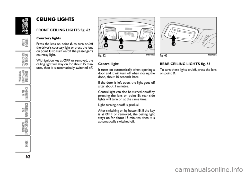
FRONT CEILING LIGHTS fig. 62
Courtesy lights
Press the lens on point Ato turn on/off
the driver’s courtesy light or press the lens
on point Cto turn on/off the passenger’s
courtesy light.
With ignition key at OFFor removed, the
ceiling light will stay on for about 15 min-
utes, then it is automatically switched off.Central light
It turns on automatically when opening a
door and it will turn off when closing the
door, about 10 seconds later.
If the door is left open, the light goes off
after about 3 minutes.
Central light can also be turned on/off by
pressing the lens on point B; rear side
lights will turn on at the same time.
Light turning on/off is gradual.
After switching on by button B, if the key
is at OFFor removed, the ceiling light
stays on for about 15 minutes, then it is
automatically switched off. REAR CEILING LIGHTS fig. 63
To turn these lights on/off, press the lens
on point D.
fig. 62F0L0105mfig. 63F0L0106m
062-098 Croma TRW GB 20-11-2006 15:01 Pagina 62
Page 63 of 240
63
SAFETY
DEVICES
CORRECT USE
OF THE CAR
WARNING
LIGHTS AND
MESSAGES
IN AN
EMERGENCY
MANUTENZIONE
E CURA
TECHNICAL
SPECIFICATIONS
INDEX
DASHBOARD
AND CONTROLS
CONTROLS
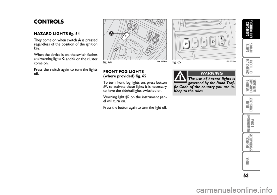
HAZARD LIGHTS fig. 64
They come on when switch Ais pressed
regardless of the position of the ignition
key.
When the device is on, the switch flashes
and warning lights
Îand ¥on the cluster
come on.
Press the switch again to turn the lights
off.fig. 64F0L0034mfig. 65F0L0035m
The use of hazard lights is
governed by the Road Traf-
fic Code of the country you are in.
Keep to the rules.
WARNINGFRONT FOG LIGHTS
(where provided) fig. 65
To turn front fog lights on, press button
5, to activate these lights it is necessary
to have the side/taillights switched on.
Warning light
5on the instrument pan-
el will turn on.
Press the button again to turn the light off.
062-098 Croma TRW GB 20-11-2006 15:01 Pagina 63
Page 64 of 240
64
SAFETY
DEVICES
CORRECT USE
OF THE CAR
WARNING
LIGHTS AND
MESSAGES
IN AN
EMERGENCY
CAR
MAINTENANCE
TECHNICAL
SPECIFICATIONS
INDEX
DASHBOARD
AND CONTROLS
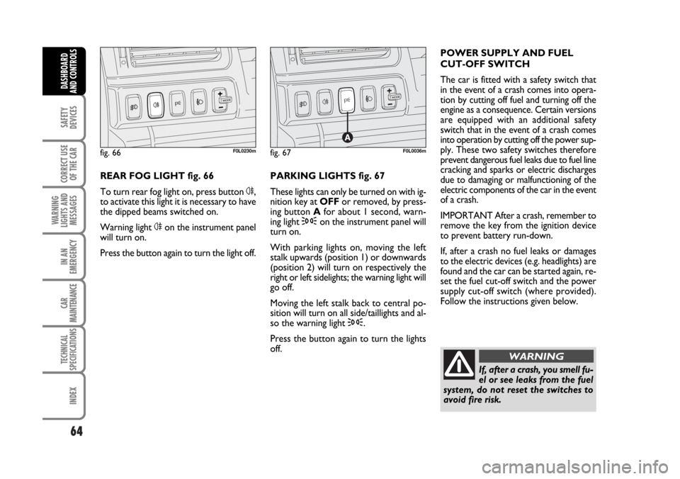
REAR FOG LIGHT fig. 66
To turn rear fog light on, press button 4,
to activate this light it is necessary to have
the dipped beams switched on.
Warning light 4on the instrument panel
will turn on.
Press the button again to turn the light off.PARKING LIGHTS fig. 67
These lights can only be turned on with ig-
nition key at OFFor removed, by press-
ing button Afor about 1 second, warn-
ing light 3on the instrument panel will
turn on.
With parking lights on, moving the left
stalk upwards (position 1) or downwards
(position 2) will turn on respectively the
right or left sidelights; the warning light will
go off.
Moving the left stalk back to central po-
sition will turn on all side/taillights and al-
so the warning light 3.
Press the button again to turn the lights
off. POWER SUPPLY AND FUEL
CUT-OFF SWITCH
The car is fitted with a safety switch that
in the event of a crash comes into opera-
tion by cutting off fuel and turning off the
engine as a consequence. Certain versions
are equipped with an additional safety
switch that in the event of a crash comes
into operation by cutting off the power sup-
ply. These two safety switches therefore
prevent dangerous fuel leaks due to fuel line
cracking and sparks or electric discharges
due to damaging or malfunctioning of the
electric components of the car in the event
of a crash.
IMPORTANT After a crash, remember to
remove the key from the ignition device
to prevent battery run-down.
If, after a crash no fuel leaks or damages
to the electric devices (e.g. headlights) are
found and the car can be started again, re-
set the fuel cut-off switch and the power
supply cut-off switch (where provided).
Follow the instructions given below.
fig. 66F0L0230mfig. 67F0L0036m
If, after a crash, you smell fu-
el or see leaks from the fuel
system, do not reset the switches to
avoid fire risk.
WARNING
062-098 Croma TRW GB 20-11-2006 15:01 Pagina 64
Page 65 of 240
65
SAFETY
DEVICES
CORRECT USE
OF THE CAR
WARNING
LIGHTS AND
MESSAGES
IN AN
EMERGENCY
CAR
MAINTENANCE
TECHNICAL
SPECIFICATIONS
INDEX
DASHBOARD
AND CONTROLS
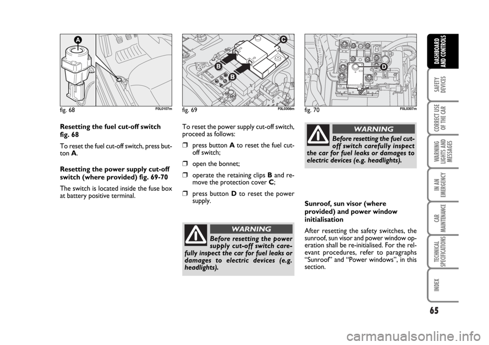
Resetting the fuel cut-off switch
fig. 68
To reset the fuel cut-off switch, press but-
ton A.
Resetting the power supply cut-off
switch (where provided) fig. 69-70
The switch is located inside the fuse box
at battery positive terminal.To reset the power supply cut-off switch,
proceed as follows:
❒press button Ato reset the fuel cut-
off switch;
❒open the bonnet;
❒operate the retaining clips Band re-
move the protection cover C;
❒press button Dto reset the power
supply.
fig. 68F0L0107mfig. 69F0L0308mfig. 70F0L0307m
Before resetting the power
supply cut-off switch care-
fully inspect the car for fuel leaks or
damages to electric devices (e.g.
headlights).
WARNING
Before resetting the fuel cut-
off switch carefully inspect
the car for fuel leaks or damages to
electric devices (e.g. headlights).
WARNING
Sunroof, sun visor (where
provided) and power window
initialisation
After resetting the safety switches, the
sunroof, sun visor and power window op-
eration shall be re-initialised. For the rel-
evant procedures, refer to paragraphs
“Sunroof” and “Power windows”, in this
section.
062-098 Croma TRW GB 20-11-2006 15:01 Pagina 65
Page 66 of 240
66
SAFETY
DEVICES
CORRECT USE
OF THE CAR
WARNING
LIGHTS AND
MESSAGES
IN AN
EMERGENCY
CAR
MAINTENANCE
TECHNICAL
SPECIFICATIONS
INDEX
DASHBOARD
AND CONTROLS
INTERIOR FITTINGS
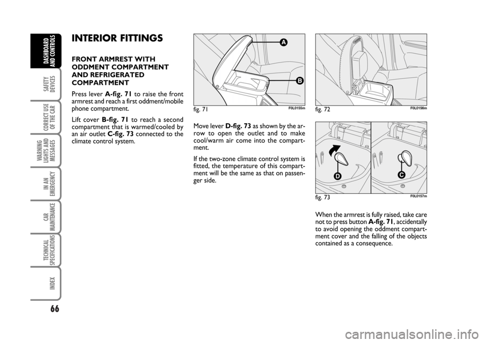
FRONT ARMREST WITH
ODDMENT COMPARTMENT
AND REFRIGERATED
COMPARTMENT
Press lever A-fig. 71to raise the front
armrest and reach a first oddment/mobile
phone compartment.
Lift cover B-fig. 71to reach a second
compartment that is warmed/cooled by
an air outlet C-fig. 73connected to the
climate control system.Move lever D-fig. 73as shown by the ar-
row to open the outlet and to make
cool/warm air come into the compart-
ment.
If the two-zone climate control system is
fitted, the temperature of this compart-
ment will be the same as that on passen-
ger side.
When the armrest is fully raised, take care
not to press button A-fig. 71, accidentally
to avoid opening the oddment compart-
ment cover and the falling of the objects
contained as a consequence.
fig. 71F0L0155mfig. 72F0L0156m
fig. 73F0L0157m
062-098 Croma TRW GB 20-11-2006 15:01 Pagina 66
Page 67 of 240
67
SAFETY
DEVICES
CORRECT USE
OF THE CAR
WARNING
LIGHTS AND
MESSAGES
IN AN
EMERGENCY
CAR
MAINTENANCE
TECHNICAL
SPECIFICATIONS
INDEX
DASHBOARD
AND CONTROLS
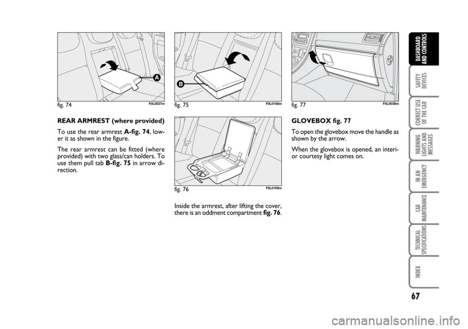
REAR ARMREST (where provided)
To use the rear armrest A-fig. 74, low-
er it as shown in the figure.
The rear armrest can be fitted (where
provided) with two glass/can holders. To
use them pull tab B-fig. 75in arrow di-
rection.
Inside the armrest, after lifting the cover,
there is an oddment compartment fig. 76. GLOVEBOX fig. 77
To open the glovebox move the handle as
shown by the arrow.
When the glovebox is opened, an interi-
or courtesy light comes on.
fig. 74F0L0037mfig. 75F0L0108m
fig. 76F0L0109m
fig. 77F0L0038m
062-098 Croma TRW GB 20-11-2006 15:01 Pagina 67
Page 68 of 240
68
SAFETY
DEVICES
CORRECT USE
OF THE CAR
WARNING
LIGHTS AND
MESSAGES
IN AN
EMERGENCY
CAR
MAINTENANCE
TECHNICAL
SPECIFICATIONS
INDEX
DASHBOARD
AND CONTROLS
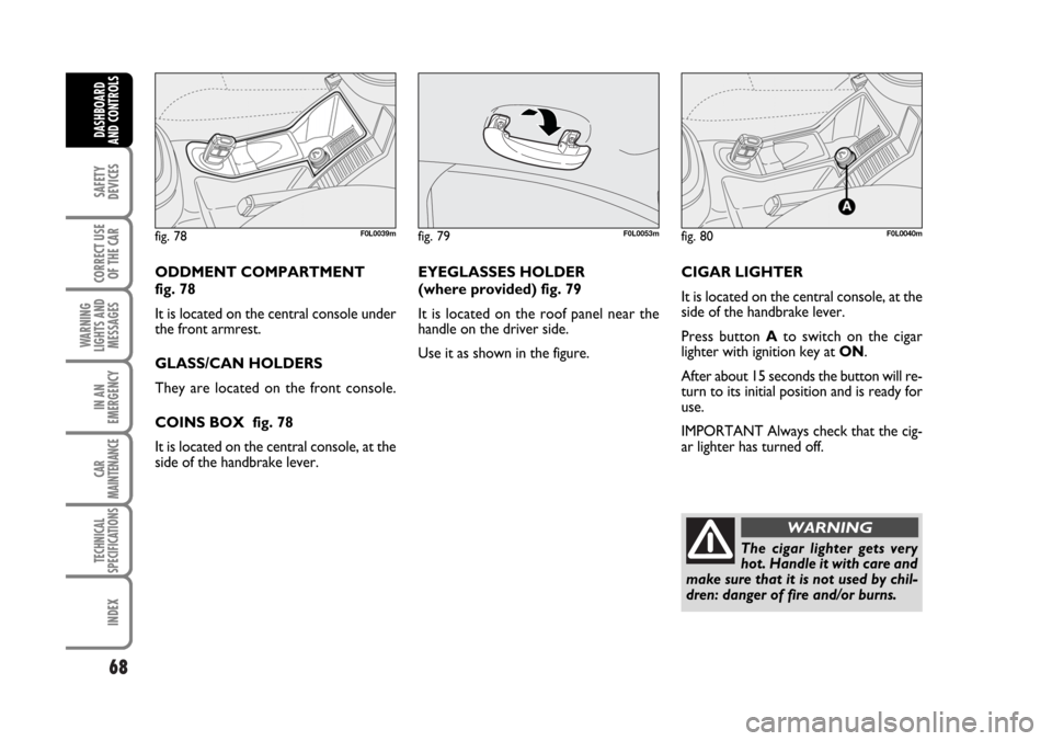
ODDMENT COMPARTMENT
fig. 78
It is located on the central console under
the front armrest.
GLASS/CAN HOLDERS
They are located on the front console.
COINS BOX fig. 78
It is located on the central console, at the
side of the handbrake lever.EYEGLASSES HOLDER
(where provided) fig. 79
It is located on the roof panel near the
handle on the driver side.
Use it as shown in the figure.CIGAR LIGHTER
It is located on the central console, at the
side of the handbrake lever.
Press button Ato switch on the cigar
lighter with ignition key at ON.
After about 15 seconds the button will re-
turn to its initial position and is ready for
use.
IMPORTANT Always check that the cig-
ar lighter has turned off.
fig. 78F0L0039mfig. 79F0L0053mfig. 80F0L0040m
The cigar lighter gets very
hot. Handle it with care and
make sure that it is not used by chil-
dren: danger of fire and/or burns.
WARNING
062-098 Croma TRW GB 20-11-2006 15:01 Pagina 68
Page 69 of 240
69
SAFETY
DEVICES
CORRECT USE
OF THE CAR
WARNING
LIGHTS AND
MESSAGES
IN AN
EMERGENCY
CAR
MAINTENANCE
TECHNICAL
SPECIFICATIONS
INDEX
DASHBOARD
AND CONTROLS
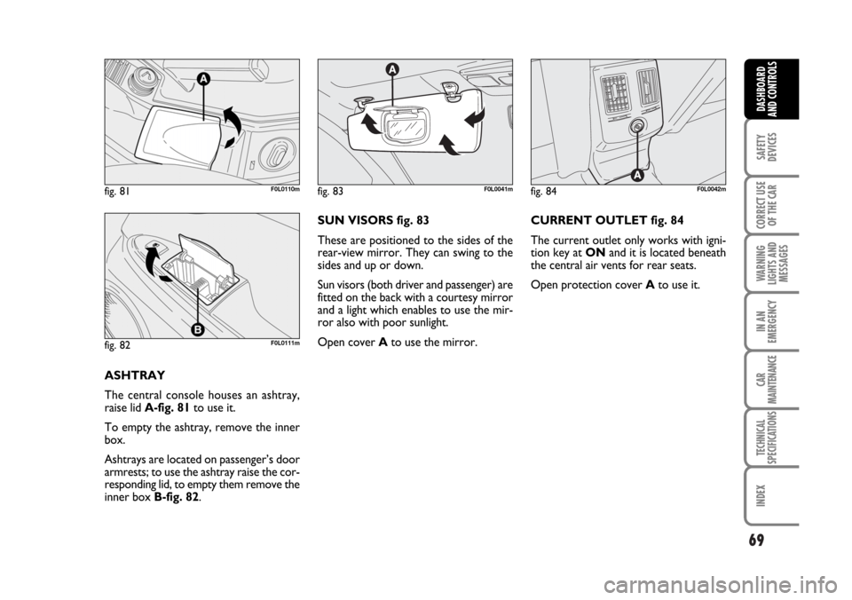
ASHTRAY
The central console houses an ashtray,
raise lid A-fig. 81to use it.
To empty the ashtray, remove the inner
box.
Ashtrays are located on passenger’s door
armrests; to use the ashtray raise the cor-
responding lid, to empty them remove the
inner box B-fig. 82.SUN VISORS fig. 83
These are positioned to the sides of the
rear-view mirror. They can swing to the
sides and up or down.
Sun visors (both driver and passenger) are
fitted on the back with a courtesy mirror
and a light which enables to use the mir-
ror also with poor sunlight.
Open cover Ato use the mirror.CURRENT OUTLET fig. 84
The current outlet only works with igni-
tion key at ONand it is located beneath
the central air vents for rear seats.
Open protection cover Ato use it.
fig. 81F0L0110m
fig. 82F0L0111m
fig. 83F0L0041mfig. 84F0L0042m
062-098 Croma TRW GB 20-11-2006 15:01 Pagina 69
Page 70 of 240
70
SAFETY
DEVICES
CORRECT USE
OF THE CAR
WARNING
LIGHTS AND
MESSAGES
IN AN
EMERGENCY
CAR
MAINTENANCE
TECHNICAL
SPECIFICATIONS
INDEX
DASHBOARD
AND CONTROLS
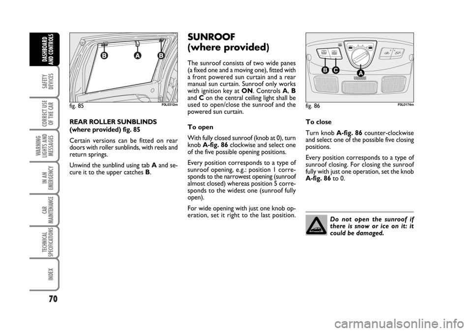
REAR ROLLER SUNBLINDS
(where provided) fig. 85
Certain versions can be fitted on rear
doors with roller sunblinds, with reels and
return springs.
Unwind the sunblind using tab Aand se-
cure it to the upper catches B.
SUNROOF
(where provided)
The sunroof consists of two wide panes
(a fixed one and a moving one), fitted with
a front powered sun curtain and a rear
manual sun curtain. Sunroof only works
with ignition key at ON. Controls A, B
and Con the central ceiling light shall be
used to open/close the sunroof and the
powered sun curtain.
To open
With fully closed sunroof (knob at 0), turn
knob A-fig. 86clockwise and select one
of the five possible opening positions.
Every position corresponds to a type of
sunroof opening, e.g.: position 1 corre-
sponds to the narrowest opening (sunroof
almost closed) whereas position 5 corre-
sponds to the widest one (sunroof fully
open).
For wide opening with just one knob op-
eration, set it right to the last position.To close
Turn knob A-fig. 86counter-clockwise
and select one of the possible five closing
positions.
Every position corresponds to a type of
sunroof closing. For closing the sunroof
fully with just one operation, set the knob
A-fig. 86to 0.
fig. 85F0L0312mfig. 86F0L0174m
Do not open the sunroof if
there is snow or ice on it: it
could be damaged.
062-098 Croma TRW GB 20-11-2006 15:01 Pagina 70