sensor FIAT CROMA 2009 2.G Owners Manual
[x] Cancel search | Manufacturer: FIAT, Model Year: 2009, Model line: CROMA, Model: FIAT CROMA 2009 2.GPages: 258, PDF Size: 5.69 MB
Page 5 of 258
4
SAFETY
DEVICES
CORRECT USE
OF THE CAR
WARNING
LIGHTS AND
MESSAGES
IN AN
EMERGENCY
CAR
MAINTENANCE
TECHNICAL
SPECIFICATIONS
INDEX
DASHBOARD
AND CONTROLSINSTRUMENT DASHBOARD........................................... 5
INSTRUMENT PANEL......................................................... 6
SYMBOLS................................................................................ 8
THE FIAT CODE SYSTEM.................................................. 9
THE KEYS............................................................................... 10
ALARM.................................................................................... 14
DEAD LOCK DEVICE......................................................... 16
IGNITION DEVICE.............................................................. 19
ON BOARD INSTRUMENTS............................................ 20
MULTIFUNCTIONAL DISPLAY ...................................... 22
RECONFIGURABLE MULTIFUNCTIONAL DISPLAY .. 25
DISPLAY FUNCTIONS........................................................ 28
TRIP COMPUTER................................................................. 36
SEATS....................................................................................... 39
HEAD RESTS.......................................................................... 42
STEERING WHEEL............................................................... 43
REAR VIEW MIRRORS ....................................................... 44
HEATING/AIR CONDITIONING SYSTEM................... 47
MANUAL AIR CONDITIONER........................................ 49
AUTOMATIC AIR CONDITIONER................................ 52
EXTERIOR LIGHTS.............................................................. 62
WINDOW CLEANING...................................................... 65CRUISE CONTROL............................................................. 68
CEILING LIGHTS.................................................................. 70
CONTROLS........................................................................... 71
INTERIOR EQUIPMENT..................................................... 74
SUN ROOF............................................................................. 78
DOORS................................................................................... 81
ELECTRIC WINDOW REGULATORS........................... 82
BOOT ...................................................................................... 84
ENGINE HOOD................................................................... 90
ROOF RACK/SKI RACK..................................................... 92
HEADLAMPS.......................................................................... 93
ABS SYSTEM........................................................................... 94
ESP SYSTEM............................................................................ 96
ASR SYSTEM.......................................................................... 97
EOBD SYSTEM...................................................................... 98
T.P.M.S. SYSTEM.................................................................... 99
CAR RADIO........................................................................... 100
USER PURCHASED ACCESSORIES................................. 101
PARKING SENSORS............................................................ 102
VEHICLE REFUELLING........................................................ 104
ENVIRONMENTAL PROTECTION................................. 105
DD D
A A
S S
H H
B B
O O
A A
R R
D D
A A
N N
D D
C C
O O
N N
T T
R R
O O
L L
S S
001-038 Croma TRW GB 28-05-2008 16:29 Pagina 4
Page 13 of 258
12
SAFETY
DEVICES
CORRECT USE
OF THE CAR
WARNING
LIGHTS AND
MESSAGES
IN AN
EMERGENCY
CAR
MAINTENANCE
TECHNICAL
SPECIFICATIONS
INDEX
DASHBOARD
AND CONTROLS
Used batteries are harmful to
the environment. They should
be disposed of as specified by
law in the special containers
provided, or take them to a Fiat Deal-
ership, which will deal with their dis-
posal. Opening the tailgate
by the remote control
Press button
Rto open the tailgate by
remote control even if the alarm (where
provided) is on.
Opening the tailgate is accompanied by the
direction indicators flashing twice; clos-
ing is accompanied by a single flash (only
if the alarm is on).
If the alarm is on, when the tailgate is
opened the alarm system switches off vol-
umetric protection and the tailgate
perimetral protection sensor.
When closing the tailgate again, volumet-
ric and perimetral protection sensors are
restored.
IMPORTANT If the remote control does
not work properly, it is however possi-
ble to open the tailgate through the me-
chanical lever set on the lock inside the
boot (see paragraph “Boot” in this sec-
tion).LED signals on door lock button
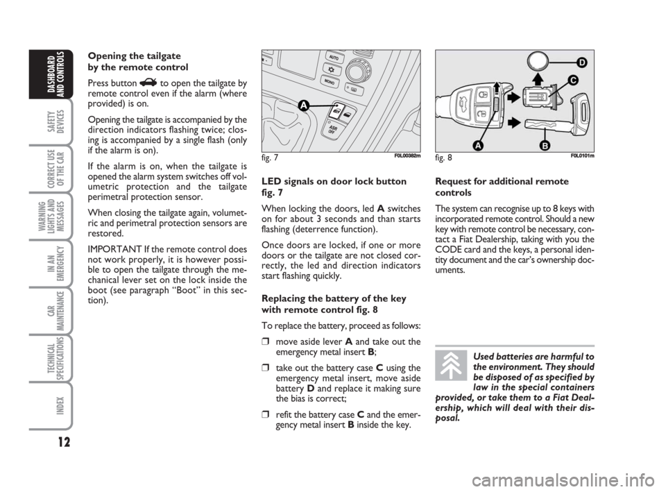
fig. 7
When locking the doors, led Aswitches
on for about 3 seconds and than starts
flashing (deterrence function).
Once doors are locked, if one or more
doors or the tailgate are not closed cor-
rectly, the led and direction indicators
start flashing quickly.
Replacing the battery of the key
with remote control fig. 8
To replace the battery, proceed as follows:
❒move aside lever Aand take out the
emergency metal insert B;
❒take out the battery case Cusing the
emergency metal insert, move aside
battery Dand replace it making sure
the bias is correct;
❒refit the battery case Cand the emer-
gency metal insert Binside the key.Request for additional remote
controls
The system can recognise up to 8 keys with
incorporated remote control. Should a new
key with remote control be necessary, con-
tact a Fiat Dealership, taking with you the
CODE card and the keys, a personal iden-
tity document and the car’s ownership doc-
uments.
fig. 7F0L00382mfig. 8F0L0101m
001-038 Croma TRW GB 28-05-2008 16:29 Pagina 12
Page 15 of 258
14
SAFETY
DEVICES
CORRECT USE
OF THE CAR
WARNING
LIGHTS AND
MESSAGES
IN AN
EMERGENCY
CAR
MAINTENANCE
TECHNICAL
SPECIFICATIONS
INDEX
DASHBOARD
AND CONTROLS
ALARM
(where provided)
WHEN THE ALARM
IS TRIGGERED
The alarm comes into action in the fol-
lowing cases:
❒unlawful opening of one of the doors,
bonnet or boot (perimetral protec-
tion);
❒attempt to start the engine with unau-
thorised key;
❒battery cable cutting;
❒presence of moving bodies in the pas-
senger’s compartment (volumetric
protection);
❒abnormal raising/sloping of the car.
Depending on the markets, the cutting in
of the alarm causes operation of the siren
and direction indicators (for about 26 sec-
onds). The ways of operating and the num-
ber of cycles may vary depending on the
markets.
A maximum number of sound/sight cycles
is however envisaged.Volumetric and anti-raising protections
can be cut off by operating the front ceil-
ing light controls (see paragraphs “Volu-
metric protection sensors” and “Anti-rais-
ing sensor” on the following pages).
IMPORTANT The engine immobiliser
function is guaranteed by the Fiat CODE
system, which is automatically activated
when the ignition key is removed.
HOW TO ACTIVATE
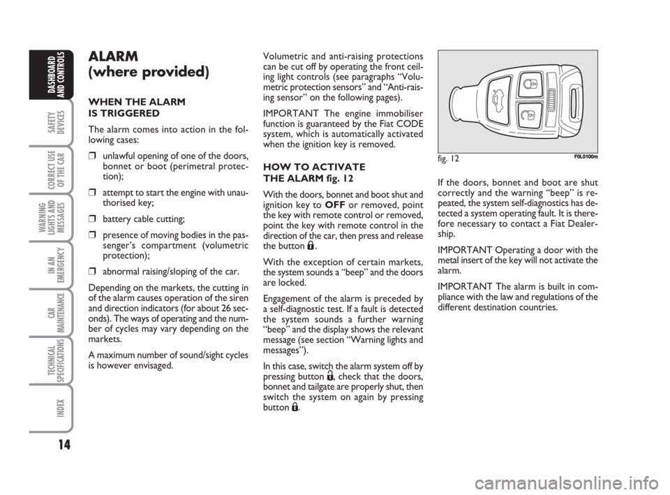
THE ALARM fig. 12
With the doors, bonnet and boot shut and
ignition key to OFFor removed, point
the key with remote control or removed,
point the key with remote control in the
direction of the car, then press and release
the button
Á.
With the exception of certain markets,
the system sounds a “beep” and the doors
are locked.
Engagement of the alarm is preceded by
a self-diagnostic test. If a fault is detected
the system sounds a further warning
“beep” and the display shows the relevant
message (see section “Warning lights and
messages”).
In this case, switch the alarm system off by
pressing button Ë, check that the doors,
bonnet and tailgate are properly shut, then
switch the system on again by pressing
button Á.
fig. 12F0L0100m
If the doors, bonnet and boot are shut
correctly and the warning “beep” is re-
peated, the system self-diagnostics has de-
tected a system operating fault. It is there-
fore necessary to contact a Fiat Dealer-
ship.
IMPORTANT Operating a door with the
metal insert of the key will not activate the
alarm.
IMPORTANT The alarm is built in com-
pliance with the law and regulations of the
different destination countries.
001-038 Croma TRW GB 28-05-2008 16:29 Pagina 14
Page 16 of 258
15
SAFETY
DEVICES
CORRECT USE
OF THE CAR
WARNING
LIGHTS AND
MESSAGES
IN AN
EMERGENCY
CAR
MAINTENANCE
TECHNICAL
SPECIFICATIONS
INDEX
DASHBOARD
AND CONTROLS
HOW TO DEACTIVATE
THE ALARM fig. 12
Press button
Ëof the key with remote
control.
The system will react as follows (with the
exception of certain markets):
❒two brief flashes of the direction in-
dicators;
❒two brief “beeps”;
❒door unlocking.
IMPORTANT Operating a door with the
metal insert of the key will not activate the
alarm.
To deactivate the alarm, turn the ignition
key to ON.
fig. 13F0L0171m
VOLUMETRIC PROTECTION
SENSORS
The volumetric sensors are located inside
the front ceiling light in the passenger’s
compartment. To make sure that the vol-
umetric sensors are working properly,
check that doors, boot, bonnet, windows
and sunroof (where provided) are shut.
Anti-raising protection
deactivation
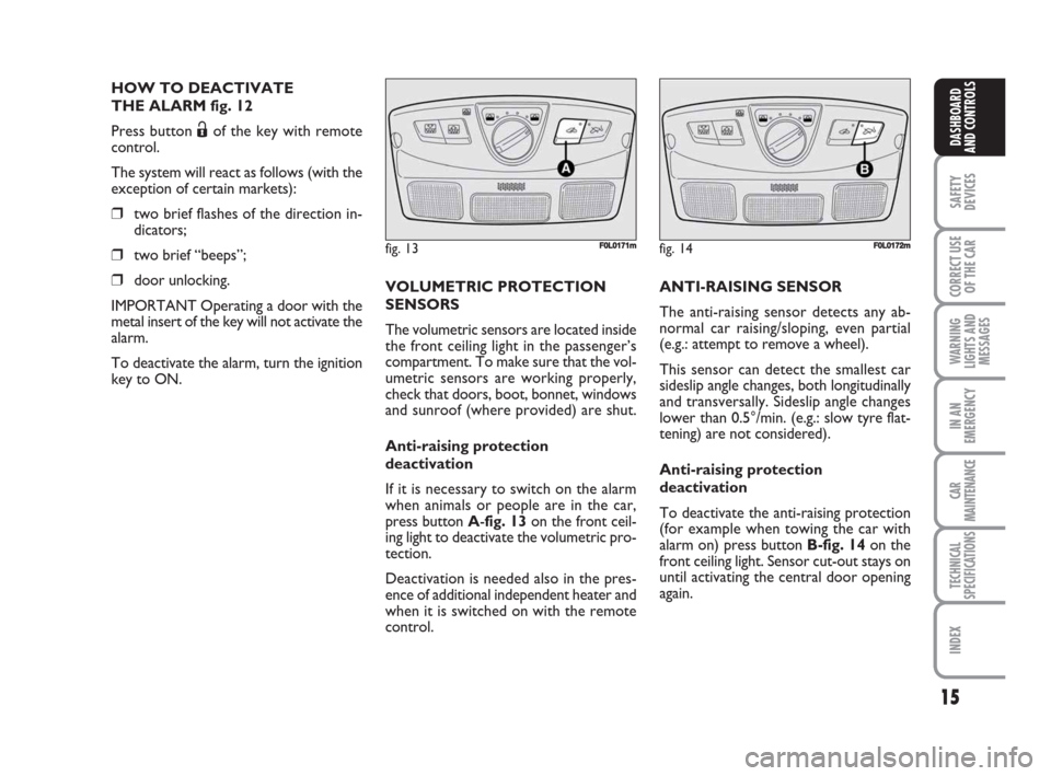
If it is necessary to switch on the alarm
when animals or people are in the car,
press button A-fig. 13 on the front ceil-
ing light to deactivate the volumetric pro-
tection.
Deactivation is needed also in the pres-
ence of additional independent heater and
when it is switched on with the remote
control.
fig. 14F0L0172m
ANTI-RAISING SENSOR
The anti-raising sensor detects any ab-
normal car raising/sloping, even partial
(e.g.: attempt to remove a wheel).
This sensor can detect the smallest car
sideslip angle changes, both longitudinally
and transversally. Sideslip angle changes
lower than 0.5°/min. (e.g.: slow tyre flat-
tening) are not considered).
Anti-raising protection
deactivation
To deactivate the anti-raising protection
(for example when towing the car with
alarm on) press button B-fig. 14on the
front ceiling light. Sensor cut-out stays on
until activating the central door opening
again.
001-038 Croma TRW GB 28-05-2008 16:30 Pagina 15
Page 24 of 258
23
SAFETY
DEVICES
CORRECT USE
OF THE CAR
WARNING
LIGHTS AND
MESSAGES
IN AN
EMERGENCY
CAR
MAINTENANCE
TECHNICAL
SPECIFICATIONS
INDEX
DASHBOARD
AND CONTROLS
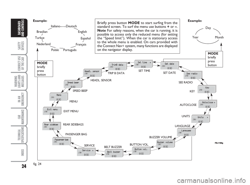
SETUP MENU fig. 24
The menu comprises a series of functions
arranged in a “circular fashion” which can
be selected through buttons +and –to
access the different select operations and
settings (setup) given in the following para-
graphs.
The setup menu can be activated by press-
ing briefly button MODE, only with the
car turned on (with car off, only the re-
duced menu can be displayed).
Single presses on buttons +or –will scroll
the setup menu options.
Handling modes differ with each other ac-
cording to the characteristic of the option
selected.
NOTE If the car is equipped with the Ra-
dionavigation System, the only functions
that can be adjusted/set through the in-
strument panel display are the following:
“Speed limit”, “Automatic headlight day-
light sensor” (where provided) and “S.B.R.
(Seat Belt Reminder) buzzer reactivation”
(where provided). The other functions are
displayed by and can be adjusted/set
through the Radionavigation System dis-
play.Selecting a menu option
– press briefly button MODEto select
the menu option to set;
– press buttons +or –(by single press-
es) to select the new setting;
– press briefly button MODEto store the
new setting and to go back to the previ-
ously selected menu option.
Selecting “Date” and “Set Clock”:
– briefly press button MODEto select
the first value to change (e.g. hours /min-
utes or year / month / day);
– press buttons +or –(by single press-
es) to select the new setting;
– briefly press button MODEto store the
new setting and to go to the next setup
menu option, if this is the last one you will
go back to the previously selected option of
the main menu.Press button MODE for long:
– to quit the setup menu and to save on-
ly the settings stored yet by the user (and
confirmed by pressing briefly button
MODE).
The setup menu displaying is timed; when
quitting the menu due to timing expiry,
only settings stored yet by the user (and
confirmed by pressing briefly button
MODE) will be saved.
001-038 Croma TRW GB 28-05-2008 16:30 Pagina 23
Page 25 of 258
24
SAFETY
DEVICES
CORRECT USE
OF THE CAR
WARNING
LIGHTS AND
MESSAGES
IN AN
EMERGENCY
CAR
MAINTENANCE
TECHNICAL
SPECIFICATIONS
INDEX
DASHBOARD
AND CONTROLS
Day
Year
MODE
briefly
press
button
Month
Deutsch
Português
English
Español
Français
Italiano
Nederland
Polski
Example:
BELT BUZZER SPEED BEEPHEADL. SENSORSET TIME
SET DATE
SEE RADIO
KEY
AUTOCLOSE
UNITS
LANGUAGE
BUZZER VOLUME
BUTTON VOL. EXIT MENU
SERVICETRIP B DATA
fig. 24Example:
MODE
briefly
press
button
Briefly press button MODEto start surfing from the
standard screen. To surf the menu use buttons +or –.
NoteFor safety reasons, when the car is running, it is
possible to access only the reduced menu (for setting
the “Speed limit”). When the car is stationary access
to the whole menu is enabled. On cars provided with
the Connect Nav+ system, many functions are displayed
on the navigator display.
F0L1195g
Turkçe
Brasilian
PASSENGER BAG REAR SIDEBAGSMENU
001-038 Croma TRW GB 28-05-2008 16:30 Pagina 24
Page 27 of 258
26
SAFETY
DEVICES
CORRECT USE
OF THE CAR
WARNING
LIGHTS AND
MESSAGES
IN AN
EMERGENCY
CAR
MAINTENANCE
TECHNICAL
SPECIFICATIONS
INDEX
DASHBOARD
AND CONTROLS
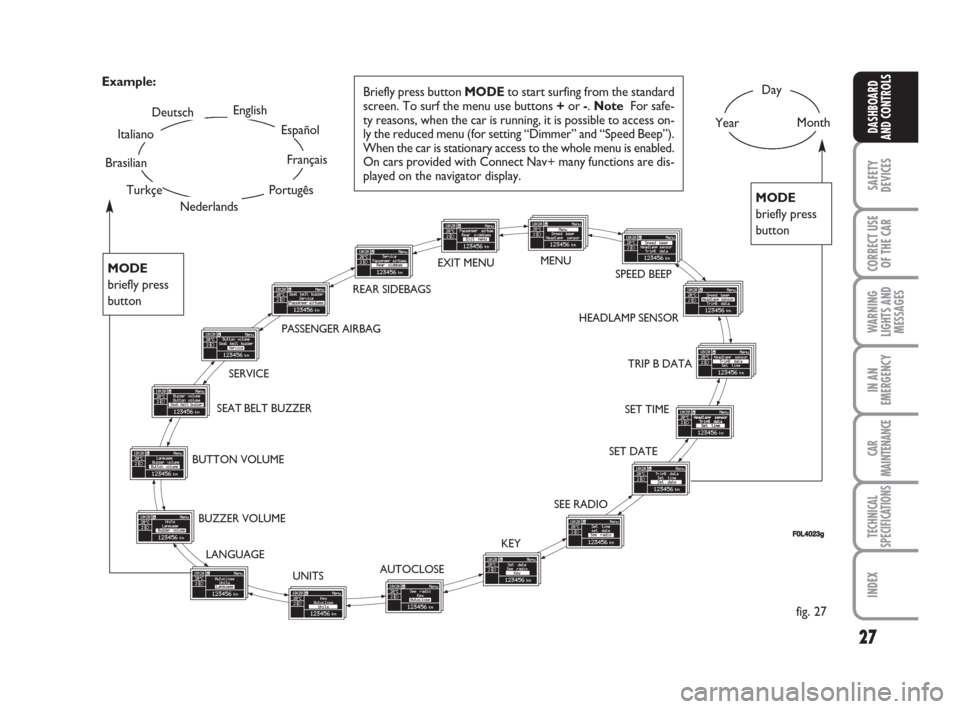
SETUP MENU fig. 27
The menu comprises a series of functions
arranged in a “circular fashion” which can
be selected through buttons +and –to
access the different select operations and
settings (setup) given below. For certain
options (Set time and Units) there is a sub-
menu.
The setup menu can be activated by press-
ing briefly button MODE.
Single presses on buttons +or –will scroll
the setup menu options. Handling modes
differ with each other according to the
characteristic of the option selected.
If the car is equipped with Connect Nav+,
the only functions that can be adjusted/set
through the instrument panel display are
the following: “Dimmer”, “Speed Beep”,
“Headl. sensor” (where provided), “Belt
buzzer” and “Passenger bag”. The other
functions are displayed by and can be ad-
justed/set through the Connect Nav+ sys-
tem display.Selecting an option in the main menu
without submenu:
– press briefly button MODEto select
the menu option to set;
– press buttons +or –(by single press-
es) to select the new setting;
– press briefly button MODEto store the
new setting and to go back to the previ-
ously selected menu option.Selecting an option in the main menu with
submenu:
– press briefly button MODEto display
the first submenu option;
– press buttons +or –(by single press-
es) to scroll all submenu options;
– press briefly button MODEto select
the displayed submenu option and to en-
ter the relevant setup menu;
– press buttons +or –(by single press-
es) to select the new setting;
– press briefly button MODEto store the
new setting and to go back to the previ-
ously selected submenu option.
001-038 Croma TRW GB 28-05-2008 16:30 Pagina 26
Page 28 of 258
27
SAFETY
DEVICES
CORRECT USE
OF THE CAR
WARNING
LIGHTS AND
MESSAGES
IN AN
EMERGENCY
CAR
MAINTENANCE
TECHNICAL
SPECIFICATIONS
INDEX
DASHBOARD
AND CONTROLS
Day
YearMonthEnglish
Portugês
Español
Français
Deutsch
Italiano
SEAT BELT BUZZERTRIP B DATA
SET DATE
SEE RADIO
KEY
AUTOCLOSE
UNITS LANGUAGE BUZZER VOLUME BUTTON VOLUMESERVICE
Briefly press button MODEto start surfing from the standard
screen. To surf the menu use buttons +or -. Note For safe-
ty reasons, when the car is running, it is possible to access on-
ly the reduced menu (for setting “Dimmer” and “Speed Beep”).
When the car is stationary access to the whole menu is enabled.
On cars provided with Connect Nav+ many functions are dis-
played on the navigator display. Example:
fig. 27
FF0L4023g
SET TIME HEADLAMP SENSORSPEED BEEP EXIT MENU
Nederlands
PASSENGER AIRBAG
Turkçe
Brasilian
MODE
briefly press
button
MODE
briefly press
button
REAR SIDEBAGSMENU
001-038 Croma TRW GB 28-05-2008 16:30 Pagina 27
Page 30 of 258
29
SAFETY
DEVICES
CORRECT USE
OF THE CAR
WARNING
LIGHTS AND
MESSAGES
IN AN
EMERGENCY
CAR
MAINTENANCE
TECHNICAL
SPECIFICATIONS
INDEX
DASHBOARD
AND CONTROLS
Headlamp sensor
(Automatic headlight sensor
sensitivity adjustment)
(where provided)
With this function it is possible to adjust
the light sensor sensitivity according to 3
levels (level 1 = min. level, level 2 = av-
erage level, level 3 = max. level); the high-
er the sensitivity is, the lower is the ex-
ternal light intensity required to switch on
the lights.
To set the light level required, proceed as
follows:
– briefly press button MODE, the previ-
ously set level will flash on the display;
– press button +or –to select the re-
quired level;
– briefly press button MODEto go back
to the menu screen or press the button
for long to go back to the standard screen
without storing settings.Trip B data (Trip On/Off)
Through this option it is possible to acti-
vate (On) or deactivate (Off) the Trip B
(partial trip).
For further information see “Trip com-
puter”.
For activation / deactivation, proceed as
follows:
– briefly press button MODE: On or Off
will flash on the display according to pre-
vious setting;
– press button +or –to select the re-
quired level;
– briefly press button MODEto go back
to the menu screen or press the button
for long to go back to the standard screen
without storing settings.Set time (Setting the clock)
This function enables to set the clock
through two sub-menus: “Time” and
“Mode”.
Proceed as follows:
– briefly press button MODE, the display
will show the two submenus “Time” and
“Mode”;
– press button +or –to scroll the two
submenus;
– select the required submenu and then
press briefly MODE;
– if selecting “Time”: briefly press button
MODE, “hours” will flash on the display;
– press button +or –for setting;
– press button MODE, “minutes” will
flash on the display;
– press button +or –for setting.
001-038 Croma TRW GB 28-05-2008 16:30 Pagina 29
Page 53 of 258
52
SAFETY
DEVICES
CORRECT USE
OF THE CAR
WARNING
LIGHTS AND
MESSAGES
IN AN
EMERGENCY
CAR
MAINTENANCE
TECHNICAL
SPECIFICATIONS
INDEX
DASHBOARD
AND CONTROLS
CLIMATE CONTROL (cooling)
Proceed as follows:
❒turn knob Cto the blue sector;
❒turn knob Eto the required speed;
❒turn knob Ato O;
❒turn air recirculation on by pressing
button G(button led on);
❒press button Bto turn climate control
compressor on.
Cooling adjustment
Proceed as follows:
❒turn air recirculation off by pressing
button G(button led off);
❒turn knob Cto the right to raise tem-
perature;
❒turn knob Eto the left to reduce the
fan speed.LOOKING AFTER THE SYSTEM
During winter, the climate control system
must be turned on at least once a month
for about 10 minutes. Before summer,
have the system checked at a Fiat Deal-
ership.
AUTOMATIC CLIMATE
CONTROL SYSTEM
(where provided)
GENERAL
The car is fitted with a two-zone climate
control system which makes it possible to
separately adjust the air temperature on
the driver’s side and on the passenger’s
side. Temperature control is based on the
“equivalent temperature” logic, i.e.: the
system continuously works to keep con-
stant the comfort inside the passenger
compartment and to compensate any vari-
ation of the outside climate conditions, in-
cluding sunshine detected by a proper sen-
sor provided for the purpose.
The system is also fitted with AQS (Air
Quality System) sensor that turns on air
recirculation automatically when it detects
the presence of outside polluted air (for
example when driving in the city, queues
and tunnels).
039-069 Croma TRW GB 10-11-2008 13:15 Pagina 52