sensor FIAT CROMA 2009 2.G User Guide
[x] Cancel search | Manufacturer: FIAT, Model Year: 2009, Model line: CROMA, Model: FIAT CROMA 2009 2.GPages: 258, PDF Size: 5.69 MB
Page 60 of 258
59
SAFETY
DEVICES
CORRECT USE
OF THE CAR
WARNING
LIGHTS AND
MESSAGES
IN AN
EMERGENCY
CAR
MAINTENANCE
TECHNICAL
SPECIFICATIONS
INDEX
DASHBOARD
AND CONTROLS
Air recirculation and AQS function
on/off button A
If the AQSsensor is not fitted, air recir-
culation works according to the following
operating logics:
❒forced switching on (inside air recir-
culation always on), indicated by sym-
bol íon the display;
❒forced switching off (air recirculation
always off with air inlet from the out-
side), indicated by symbol
êon the
display.
The above operating conditions are ob-
tained by pressing in sequence the air re-
circulation button A.
Due to safety reasons, after long recircu-
lation activation (over 25 minutes), the
system will deactivate automatically air re-
circulation for 60 seconds to enable out-
side air inlet.
IMPORTANT The inside air recirculation
system makes it possible to reach the re-
quired heating or cooling conditions faster. It is however inadvisable to use it on
rainy/cold days as it would considerably in-
crease the possibility of the windows mist-
ing inside, especially if the climate control
system is off.
When outside temperature is below 3°C,
recirculation is forced to off (outside air
inlet) to prevent window misting up.
It will be reactivated automatically if out-
side temperature becomes higher than 5
°C.
The AQSsensor (Air Quality System) in
addition to the above operating logics, en-
ables to control recirculation automati-
cally according to the quality of outside air:
❒automatic control indicated by symbol
≥on the display.
In this event the display will show symbol
ïor ñaccording to actual recircu-
lation operating conditions (on or off).
In automatic operation with AQS,inside
air recirculation is turned on automatical-
ly when the antipollution sensor detectsthe presence of polluted air, for example
when driving in the city, queues and tun-
nels.
With compressor on, in order to prevent
polluted air (exhaust gas) inlet at stops, the
system will stop air recirculation when the
car speed falls below 6 km/h. As the car
speed increases (over 25 km/h), the sys-
tem will restore the previous automatic
operating conditions.
In automatic operation, AQSis deacti-
vated when outside temperature is below
3°C, the system will activate air recircu-
lation (indicated by symbol ≥on the
display). The user can however set it man-
ually by operating in rolling mode the reir-
culation button: pressing the button for
the first time will display the current re-
circulation condition, indicated by symbol
ê.
It will be reactivated automatically if out-
side temperature becomes higher than 5
°C.
Press the button again to select the re-
quired recirculation condition, indicated
by the corresponding symbol on the dis-
play. Under these conditions manual ac-
tivation of the AQSfunction could cause
window misting up.
When air recirculation is set manually,
wording FULLwill turn off and A will dis-
appear from the recirculation symbol on
the display.
It is inadvisable to use the in-
side air recirculation func-
tion with low outside temperature as
windows may mist over quickly.
WARNING
039-069 Croma TRW GB 10-11-2008 13:15 Pagina 59
Page 65 of 258
64
SAFETY
DEVICES
CORRECT USE
OF THE CAR
WARNING
LIGHTS AND
MESSAGES
IN AN
EMERGENCY
CAR
MAINTENANCE
TECHNICAL
SPECIFICATIONS
INDEX
DASHBOARD
AND CONTROLS
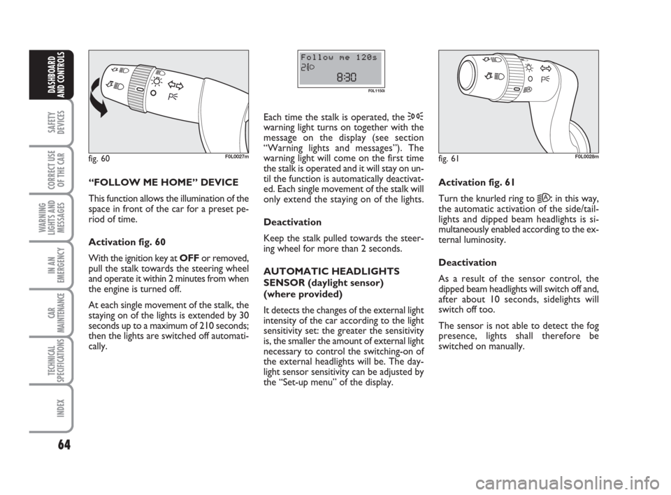
“FOLLOW ME HOME” DEVICE
This function allows the illumination of the
space in front of the car for a preset pe-
riod of time.
Activation fig. 60
With the ignition key at OFFor removed,
pull the stalk towards the steering wheel
and operate it within 2 minutes from when
the engine is turned off.
At each single movement of the stalk, the
staying on of the lights is extended by 30
seconds up to a maximum of 210 seconds;
then the lights are switched off automati-
cally. Each time the stalk is operated, the 3
warning light turns on together with the
message on the display (see section
“Warning lights and messages”). The
warning light will come on the first time
the stalk is operated and it will stay on un-
til the function is automatically deactivat-
ed. Each single movement of the stalk will
only extend the staying on of the lights.
Deactivation
Keep the stalk pulled towards the steer-
ing wheel for more than 2 seconds.
AUTOMATIC HEADLIGHTS
SENSOR (daylight sensor)
(where provided)
It detects the changes of the external light
intensity of the car according to the light
sensitivity set: the greater the sensitivity
is, the smaller the amount of external light
necessary to control the switching-on of
the external headlights will be. The day-
light sensor sensitivity can be adjusted by
the “Set-up menu” of the display.
fig. 60F0L0027m
F0L1150i
Activation fig. 61
Turn the knurled ring to
2A:in this way,
the automatic activation of the side/tail-
lights and dipped beam headlights is si-
multaneously enabled according to the ex-
ternal luminosity.
Deactivation
As a result of the sensor control, the
dipped beam headlights will switch off and,
after about 10 seconds, sidelights will
switch off too.
The sensor is not able to detect the fog
presence, lights shall therefore be
switched on manually.
fig. 61F0L0028m
039-069 Croma TRW GB 10-11-2008 13:15 Pagina 64
Page 67 of 258
66
SAFETY
DEVICES
CORRECT USE
OF THE CAR
WARNING
LIGHTS AND
MESSAGES
IN AN
EMERGENCY
CAR
MAINTENANCE
TECHNICAL
SPECIFICATIONS
INDEX
DASHBOARD
AND CONTROLS
RAIN SENSOR (where provided)
The rain sensor is located behind the dri-
ving mirror in contact with the windscreen
and has the purpose of automatically ad-
just, during the intermittent operation, the
frequency of the windscreen wiper
strokes as to the rain intensity.
IMPORTANT Keep clean the glass in the
sensor area.
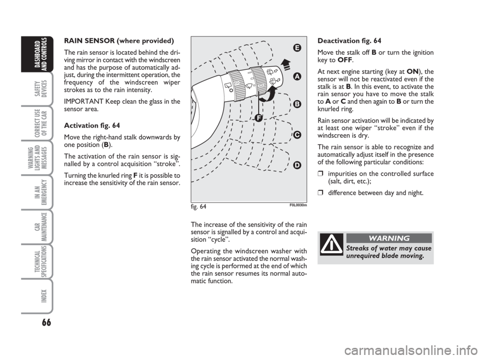
Activation fig. 64
Move the right-hand stalk downwards by
one position (B).
The activation of the rain sensor is sig-
nalled by a control acquisition “stroke”.
Turning the knurled ring Fit is possible to
increase the sensitivity of the rain sensor.
The increase of the sensitivity of the rain
sensor is signalled by a control and acqui-
sition “cycle”.
Operating the windscreen washer with
the rain sensor activated the normal wash-
ing cycle is performed at the end of which
the rain sensor resumes its normal auto-
matic function.Deactivation fig. 64
Move the stalk off Bor turn the ignition
key to OFF.
At next engine starting (key at ON), the
sensor will not be reactivated even if the
stalk is at B. In this event, to activate the
rain sensor you have to move the stalk
to Aor Cand then again to Bor turn the
knurled ring.
Rain sensor activation will be indicated by
at least one wiper “stroke” even if the
windscreen is dry.
The rain sensor is able to recognize and
automatically adjust itself in the presence
of the following particular conditions:
❒impurities on the controlled surface
(salt, dirt, etc.);
❒difference between day and night.
fig. 64F0L0030m
Streaks of water may cause
unrequired blade moving.
WARNING
039-069 Croma TRW GB 10-11-2008 13:15 Pagina 66
Page 101 of 258
100
SAFETY
DEVICES
CORRECT USE
OF THE CAR
WARNING
LIGHTS AND
MESSAGES
IN AN
EMERGENCY
CAR
MAINTENANCE
TECHNICAL
SPECIFICATIONS
INDEX
DASHBOARD
AND CONTROLS
IMPORTANT NOTES ABOUT
THE T.P.M.S. SYSTEM
Failure indications will not be stored and
therefore will not be displayed when turn-
ing the engine off and on again. If failure
persists, the control unit will send warn-
ing indications to the instrument panel on-
ly after a few seconds when the car is
moving.
IMPORTANT T.P.M.S. system cannot in-
dicate sudden tyre pressure drops (e.g.:
tyre burst). In this event, brake the car
cautiously and avoid sudden steering.
IMPORTANT Replacing standard tyres
with winter tyres and vice versa involves
T.P.M.S. system set-up that shall be per-
formed at Fiat Dealerships only.
IMPORTANT The T.P.M.S. system re-
quires special equipment. Consult Fiat
Dealership to know what type of acces-
sories are compatible with the system
(wheels, wheel caps, etc.). Using other ac-
cessories could cause system malfunc-
tioning.IMPORTANT Tyre pressure could change
according to outside temperature. For this
reason the T.P.M.S. system could tem-
porarily indicate low tyre pressure. In this
event check pressure with cold tyres and
restore proper inflation values if required.
IMPORTANT If the car is fitted with
T.P.M.S. system, tyre and/or rim removal
and refitting operations involve special
precautions; to prevent damages or wrong
sensor refitting, contact Fiat Dealership to
have tyre and/or rim changed.
IMPORTANT If the car is fitted with
T.P.M.S. system, when changing a tyre,
change also the rubber seal of the valve.
Contact a Fiat Dealership.
IMPORTANT Strong radiofrequency
noise may inhibit regular TPMS system op-
eration; in this event, a dedicated message
will be displayed to warn the driver. This
message will disappear automatically as
soon as noise disappears.SOUND SYSTEM
(where provided)
For the operation of the radio with
CD/MP3 CD (where provided), read the
instructions for use given in the Supple-
ment attached to the Owner Handbook.
SOUND SYSTEM
(where provided)
The system includes:
❒2 tweeters (power 40W max. each),
located on front doors;
❒2 mid-woofers, (diameter 165 mm,
power 40W max. each), located on
front doors;
❒2 full-range speakers, (diameter 165
mm, power 40W max. each), located
on rear doors.
070-106 Croma TRW GB 19-02-2009 15:03 Pagina 100
Page 103 of 258
102
SAFETY
DEVICES
CORRECT USE
OF THE CAR
WARNING
LIGHTS AND
MESSAGES
IN AN
EMERGENCY
CAR
MAINTENANCE
TECHNICAL
SPECIFICATIONS
INDEX
DASHBOARD
AND CONTROLS
PARKING SENSORS
(where provided)
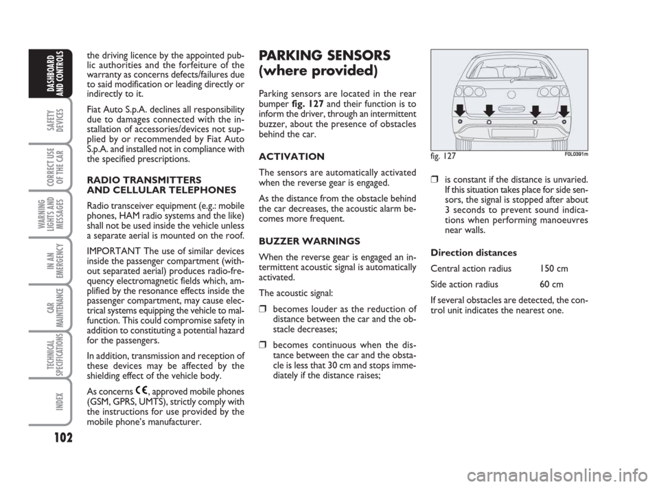
Parking sensors are located in the rear
bumper fig. 127and their function is to
inform the driver, through an intermittent
buzzer, about the presence of obstacles
behind the car.
ACTIVATION
The sensors are automatically activated
when the reverse gear is engaged.
As the distance from the obstacle behind
the car decreases, the acoustic alarm be-
comes more frequent.
BUZZER WARNINGS
When the reverse gear is engaged an in-
termittent acoustic signal is automatically
activated.
The acoustic signal:
❒becomes louder as the reduction of
distance between the car and the ob-
stacle decreases;
❒becomes continuous when the dis-
tance between the car and the obsta-
cle is less that 30 cm and stops imme-
diately if the distance raises;
❒is constant if the distance is unvaried.
If this situation takes place for side sen-
sors, the signal is stopped after about
3 seconds to prevent sound indica-
tions when performing manoeuvres
near walls.
Direction distances
Central action radius 150 cm
Side action radius 60 cm
If several obstacles are detected, the con-
trol unit indicates the nearest one.
fig. 127F0L0391m
the driving licence by the appointed pub-
lic authorities and the forfeiture of the
warranty as concerns defects/failures due
to said modification or leading directly or
indirectly to it.
Fiat Auto S.p.A. declines all responsibility
due to damages connected with the in-
stallation of accessories/devices not sup-
plied by or recommended by Fiat Auto
S.p.A. and installed not in compliance with
the specified prescriptions.
RADIO TRANSMITTERS
AND CELLULAR TELEPHONES
Radio transceiver equipment (e.g.: mobile
phones, HAM radio systems and the like)
shall not be used inside the vehicle unless
a separate aerial is mounted on the roof.
IMPORTANT The use of similar devices
inside the passenger compartment (with-
out separated aerial) produces radio-fre-
quency electromagnetic fields which, am-
plified by the resonance effects inside the
passenger compartment, may cause elec-
trical systems equipping the vehicle to mal-
function. This could compromise safety in
addition to constituting a potential hazard
for the passengers.
In addition, transmission and reception of
these devices may be affected by the
shielding effect of the vehicle body.
As concerns , approved mobile phones
(GSM, GPRS, UMTS), strictly comply with
the instructions for use provided by the
mobile phone’s manufacturer.
070-106 Croma TRW GB 19-02-2009 15:03 Pagina 102
Page 104 of 258
103
SAFETY
DEVICES
CORRECT USE
OF THE CAR
WARNING
LIGHTS AND
MESSAGES
IN AN
EMERGENCY
CAR
MAINTENANCE
TECHNICAL
SPECIFICATIONS
INDEX
DASHBOARD
AND CONTROLS
GENERAL WARNINGS
❒When parking, take the utmost care
to obstacles that may be set above or
under the sensors.
❒Objects set close to the car, under
certain circumstances are not detect-
ed and could therefore cause damages
to the car or be damaged.
❒Indications sent by the sensors can be
altered by dirt, snow or ice deposit-
ed on the sensors or by ultrasound
systems (e.g.: truck pneumatic brakes
or pneumatic hammers) set nearby the
car. For proper operation, the
parking sensors shall always
be clean from mud, dirt, snow
or ice. When cleaning the sen-
sors, take the utmost care to prevent
their damaging; do not use therefore
dry or rough clothes. Sensors shall be
washed with clean water and car de-
tergent, if required.
Parking manoeuvres howev-
er are always under the dri-
ver’s responsibility that shall always
check the absence of people (spe-
cially children) or animals in the ma-
noeuvre space. This system is just a
help for the driver but she/he shall
never reduce attention during dan-
gerous manoeuvres even if performed
at low speed.
WARNING
FAILURE INDICATIONS
In the event of sensor failures, the driver
is warned by the turning on of warning
light
èon the instrument panel and by
the relevant message on the display (see
section “Warning lights and messages”).
OPERATION WITH TRAILER
Parking sensor operation is deactivated
automatically when the trailer electric ca-
ble plug is fitted into the car tow hook
socket.
Sensors are reactivated when removing
the trailer cable plug.
In washing stations, clean sensors quickly
keeping the vapour jet/high pressure
washing nozzles at 10 cm at least from the
sensors.
070-106 Croma TRW GB 19-02-2009 15:03 Pagina 103
Page 106 of 258
105
SAFETY
DEVICES
CORRECT USE
OF THE CAR
WARNING
LIGHTS AND
MESSAGES
IN AN
EMERGENCY
CAR
MAINTENANCE
TECHNICAL
SPECIFICATIONS
INDEX
DASHBOARD
AND CONTROLS
PROTECTING THE
ENVIRONMENT
The devices for curtailing petrol engine
emissions are the following:
❒three-way catalytic converter;
❒Lambda sensor;
❒fuel evaporation system.
In addition, do not let the engine run, even
for a test, with one or more spark plugs
disconnected.
The devices for curtailing diesel fuel en-
gine emissions are the following:
❒oxidising catalytic converter;
❒exhaust gas recirculation system
(E.G.R.);
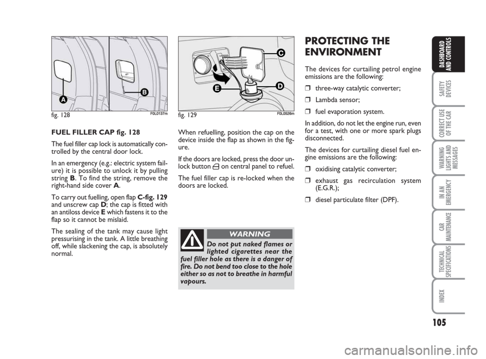
❒diesel particulate filter (DPF). FUEL FILLER CAP fig. 128
The fuel filler cap lock is automatically con-
trolled by the central door lock.
In an emergency (e.g.: electric system fail-
ure) it is possible to unlock it by pulling
string B. To find the string, remove the
right-hand side cover A.
To carry out fuelling, open flap C-fig. 129
and unscrew cap D; the cap is fitted with
an antiloss device Ewhich fastens it to the
flap so it cannot be mislaid.
The sealing of the tank may cause light
pressurising in the tank. A little breathing
off, while slackening the cap, is absolutely
normal.When refuelling, position the cap on the
device inside the flap as shown in the fig-
ure.
If the doors are locked, press the door un-
lock button
´on central panel to refuel.
The fuel filler cap is re-locked when the
doors are locked.
fig. 128F0L0137m
Do not put naked flames or
lighted cigarettes near the
fuel filler hole as there is a danger of
fire. Do not bend too close to the hole
either so as not to breathe in harmful
vapours.
WARNING
fig. 129F0L0526m
070-106 Croma TRW GB 19-02-2009 15:03 Pagina 105
Page 153 of 258
Warning light vturns on
together with the dedicated
message on the display to in-
dicate that the cleaning pro-
cedure cannot be performed, contact
Fiat Dealership as soon as possible.
152
IN AN
EMERGENCY
CAR
MAINTENANCE
TECHNICAL
SPECIFICATIONS
INDEX
DASHBOARD
AND CONTROLS
SAFETY
DEVICES
CORRECT USE
OF THE CAR
WARNING
LIGHTS AND
MESSAGES
GENERIC FAILURE
INDICATION
(amber)
The warning light turns on in the follow-
ing circumstances.
Engine oil pressure
sensor failure
The warning light comes on when the en-
gine oil pressure sensor is faulty. Contact
Fiat Dealership as soon as possible.
The display will show the dedicated mes-
sage.
è
EXTERNAL LIGHT
FAILURE (amber)
The warning light turns on
when one of the following lights is failing:
– side/taillights
– brake lights (third brake light excluded)
– rear fog lights
– direction indicators
– number plate lights.
The failure referring to these lights could
be: one or more blown bulbs, a blown
protection fuse or an electric connection
cut-off.
The display will show the dedicated mes-
sage.
W
REAR FOG LIGHTS
(amber)
The warning light turns on
when the rear fog lights are turned on.
4
Diesel particulate filter clogged
(Multijet versions)
The warning light turns on together with
the message on the display and the buzzer
when the diesel particulate filter is clogged
and the driving conditions do not enable
to activate automatically the reclaiming
procedure.
To enable the cleaning procedure, keep
the car running until the warning light
turns off.
Inertial fuel cut-off switch
intervened
The warning light turns on together with
the message on the display, when the in-
ertial fuel cut-off switch is triggered.
To reset the fuel cut-off switch, see para-
graph “Power and fuel cut-off switch” in
section “Dashboard and controls”.
Rain sensor failure
The warning light on the dial turns on (on
certain versions together with the mes-
sage on the display) when the rain sensor
is faulty. Contact Fiat Dealership.
145-156 Croma TRW GB 28-05-2008 15:18 Pagina 152
Page 154 of 258
153
IN AN
EMERGENCY
CAR
MAINTENANCE
TECHNICAL
SPECIFICATIONS
INDEX
DASHBOARD
AND CONTROLS
SAFETY
DEVICES
CORRECT USE
OF THE CAR
WARNING
LIGHTS AND
MESSAGES
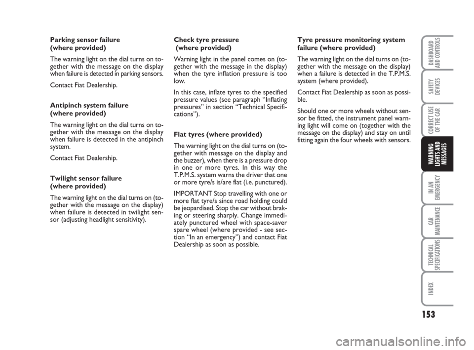
Parking sensor failure
(where provided)
The warning light on the dial turns on to-
gether with the message on the display
when failure is detected in parking sensors.
Contact Fiat Dealership.
Antipinch system failure
(where provided)
The warning light on the dial turns on to-
gether with the message on the display
when failure is detected in the antipinch
system.
Contact Fiat Dealership.
Twilight sensor failure
(where provided)
The warning light on the dial turns on (to-
gether with the message on the display)
when failure is detected in twilight sen-
sor (adjusting headlight sensitivity).Check tyre pressure
(where provided)
Warning light in the panel comes on (to-
gether with the message in the display)
when the tyre inflation pressure is too
low.
In this case, inflate tyres to the specified
pressure values (see paragraph “Inflating
pressures” in section “Technical Specifi-
cations”).
Flat tyres (where provided)
The warning light on the dial turns on (to-
gether with message on the display and
the buzzer), when there is a pressure drop
in one or more tyres. In this way the
T.P.M.S. system warns the driver that one
or more tyre/s is/are flat (i.e. punctured).
IMPORTANT Stop travelling with one or
more flat tyre/s since road holding could
be jeopardised. Stop the car without brak-
ing or steering sharply. Change immedi-
ately punctured wheel with space-saver
spare wheel (where provided - see sec-
tion “In an emergency”) and contact Fiat
Dealership as soon as possible.Tyre pressure monitoring system
failure (where provided)
The warning light on the dial turns on (to-
gether with the message on the display)
when a failure is detected in the T.P.M.S.
system (where provided).
Contact Fiat Dealership as soon as possi-
ble.
Should one or more wheels without sen-
sor be fitted, the instrument panel warn-
ing light will come on (together with the
message on the display) and stay on until
fitting again the four wheels with sensors.
145-156 Croma TRW GB 28-05-2008 15:18 Pagina 153
Page 187 of 258
186
WARNING
LIGHTS AND
MESSAGES
CAR
MAINTENANCE
TECHNICAL
SPECIFICATIONS
INDEX
DASHBOARD
AND CONTROLS
SAFETY
DEVICES
CORRECT USE
OF THE CAR
IN AN
EMERGENCY
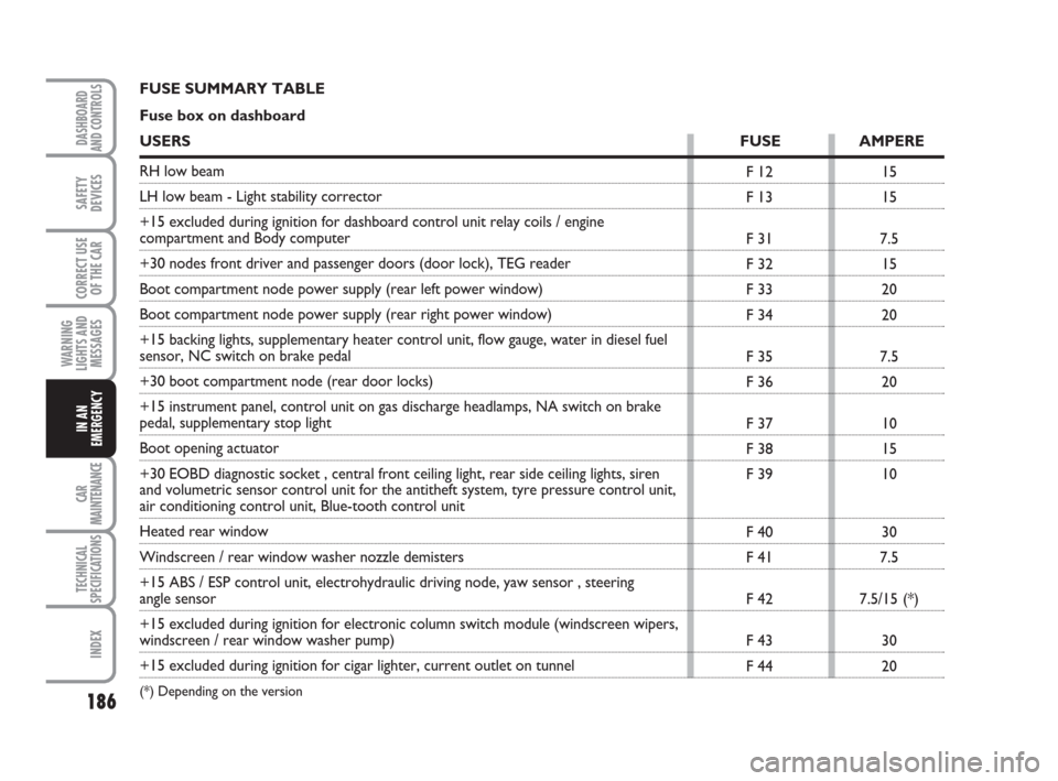
F 12
F 13
F 31
F 32
F 33
F 34
F 35
F 36
F 37
F 38
F 39
F 40
F 41
F 42
F 43
F 4415
15
7.5
15
20
20
7.5
20
10
15
10
30
7.5
7.5/15 (*)
30
20 FUSE SUMMARY TABLE
Fuse box on dashboard
USERSFUSE AMPERE
RH low beam
LH low beam - Light stability corrector
+15 excluded during ignition for dashboard control unit relay coils / engine
compartment and Body computer
+30 nodes front driver and passenger doors (door lock), TEG reader
Boot compartment node power supply (rear left power window)
Boot compartment node power supply (rear right power window)
+15 backing lights, supplementary heater control unit, flow gauge, water in diesel fuel
sensor, NC switch on brake pedal
+30 boot compartment node (rear door locks)
+15 instrument panel, control unit on gas discharge headlamps, NA switch on brake
pedal, supplementary stop light
Boot opening actuator
+30 EOBD diagnostic socket , central front ceiling light, rear side ceiling lights, siren
and volumetric sensor control unit for the antitheft system, tyre pressure control unit,
air conditioning control unit, Blue-tooth control unit
Heated rear window
Windscreen / rear window washer nozzle demisters
+15 ABS / ESP control unit, electrohydraulic driving node, yaw sensor , steering
angle sensor
+15 excluded during ignition for electronic column switch module (windscreen wipers,
windscreen / rear window washer pump)
+15 excluded during ignition for cigar lighter, current outlet on tunnel
(*) Depending on the version
157-192 Croma TRW GB 19-02-2009 14:58 Pagina 186