heating FIAT DOBLO 2009 2.G User Guide
[x] Cancel search | Manufacturer: FIAT, Model Year: 2009, Model line: DOBLO, Model: FIAT DOBLO 2009 2.GPages: 274, PDF Size: 6.6 MB
Page 55 of 274
54
KNOW
YOUR
VEHICLE
SAFETY
STARTING
AND
DRIVING
WARNING
LIGHTS AND
MESSAGES
IN AN
EMERGENCY
SERVICING
AND
MAINTENANCE
TECHNICAL
SPECIFICATIONS
INDEX
Air distribution buttons (B)
By pressing these buttons, it is possible to set one of the
seven possible air distributions manually:
▲Air flow to the windscreen and front side window dif-
fusers to demist or defrost them.
˙Air flow to the centre and side dashboard diffusers to
ventilate the chest and the face during the hot
season.
▼Air flow to the front and rear footwell diffusers.
Thanks to the natural tendency of hot air to rise up-
wards, this distribution pattern allows the passenger
compartment to warm up as quickly as possible, pro-
viding an immediate feeling of warmth.
˙
▼Air flow distribution split between footwell diffusers
(hotter air) and central and side dashboard vents
(cooler air). This distribution mode is particularly use-
ful in spring and autumn on sunny days.
▲
▼Air flow distribution split between the footwell dif-
fusers and the windscreen and front side windows de-
frosting/demisting diffusers. This allows an adequate
warming of the passenger compartment and prevents
the windows from steaming up. This function may be used to heat up the passenger com-
partment exploiting the system potential to the maximum.
In this condition, the system stops controlling the tem-
perature automatically and sets the air mixing to maximum
heating. The air speed and distribution are fixed.
In particular, if the heating fluid is not sufficiently hot, the
maximum fan speed does not come on straight away in or-
der to limit the intake of insufficiently hot air into the pas-
senger compartment.
All manual settings will be allowed when this function
is on.
To switch the function off, simply turn the temperature
knob anticlockwise and set the required temperature.
❒LO function (maximum cooling):
select by turning the temperature knob anticlockwise un-
der the minimum value (16 °C).
This function may be used to cool down the passenger
compartment exploiting the system potential to the max-
imum. In this condition, the system stops controlling the
temperature automatically and sets the air mixing to max-
imum cooling. The air speed and distribution are fixed. All
manual settings will be allowed when this function is on.
To switch the function off, simply turn the temperature
knob clockwise and set the required temperature.
Page 57 of 274

56
KNOW
YOUR
VEHICLE
SAFETY
STARTING
AND
DRIVING
WARNING
LIGHTS AND
MESSAGES
IN AN
EMERGENCY
SERVICING
AND
MAINTENANCE
TECHNICAL
SPECIFICATIONS
INDEX
It is however not advised to use it on rainy/cold days as
it would considerably increase the possibility of the win-
dows steaming up, especially if the climate control com-
pressor is off.
The recirculation is forced off (i.e. air is introduced from
the outside) when the the outside temperature is cold to
prevent misting up.
It is advisable not to use the air recirculation function when
the outside temperature is low, because the windows
could rapidly steam up.
Climate control compressor on/off button (F)
Press button √to switch the climate control compres-
sor off (if it is already on). The icon on the display will
go out.
Press the button when the LED is off to automatically
restore system control and use of the compressor. The
icon will light up in the display in this case.
The system will switch the recirculation off when the cli-
mate control compressor is switched off to prevent the
windows misting up. Although the system is capable of
maintaining the required temperature, the word FULL will
disappear from the display. If the system is no longer able
to maintain the temperature, the figures will flash and the
word AUTO will go out. WARNING Should the system (after manual intervention)
no longer be able to guarantee the target temperature for
the passenger compartment, the set temperature value will
start flashing to indicate the difficulties the system is ex-
periencing and then the word AUTO will go out.
To restore system automatic control at any time, after one
or more manual adjustments, press the AUTO
button.
Air recirculation on/off button (G)
The air recirculation works according to the following op-
erating logic:
❒override on (air recirculation always on), indicated by
the LED on the button
Gcoming on and the symbol
íon the display;
❒override off (air recirculation always off and intro-
duction of outside air), indicated by the fact that the
LED in the button goes off and symbol êwill ap-
pear on the display.
These operating conditions are obtained by pressing air
recirculation button G in sequence.
WARNING The engagement of the air recirculation sys-
tem makes it possible to reach the required heating or
cooling conditions faster.
Page 119 of 274

F0V0106mfig. 113118
KNOW
YOUR
VEHICLE
SAFETY
STARTING
AND
DRIVING
WARNING
LIGHTS AND
MESSAGES
IN AN
EMERGENCY
SERVICING
AND
MAINTENANCE
TECHNICAL
SPECIFICATIONS
INDEXThe pretensioner can be used only once.
Go to a Fiat Dealership to have it replaced
after it has been deployed. See the label inside the
glove box to check the status of the device; go to
a Fiat Dealership when it is time to replace it.
WARNING
Operations which lead to knocks, vibrations
or localised heating (over 100 °C for a max-
imum of six hours) in the area around the
pretensioners may damage or trigger them. These
devices are not affected by vibrations caused by
uneven road surfaces or low obstacles such as kerbs,
etc. Contact a Fiat Dealership for any assistance.
GENERAL INSTRUCTIONS FOR USING THE
SEAT BELTS
The driver is responsible for respecting (and ensuring that
all the other passengers also respect) the local laws in
force regarding the use of seat belts. Always fasten the
seat belts before setting off.
Seat belts must also be worn by expectant mothers: the
risk of injury in the event of an accident is greatly reduced
for them and the unborn child if they are wearing a seat
belt. Pregnant women must position the lower part of
the belt very low down so that it passes over the hips and
under the abdomen (see fig. 113).
LOAD LIMITERS
(for versions/markets where provided)
To increase passenger safety, the front and rear (for ver-
sions/markets where provided) seat belt reels contain a
load limiter which controls the force acting on the chest
and shoulders during the belt restraining action in the
event of a head-on collision.
Page 135 of 274

134
KNOW
YOUR
VEHICLE
SAFETY
STARTING
AND
DRIVING
WARNING
LIGHTS AND
MESSAGES
IN AN
EMERGENCY
SERVICING
AND
MAINTENANCE
TECHNICAL
SPECIFICATIONS
INDEXSTARTING PROCEDURE FOR DIESEL
VERSIONS
Proceed as follows:
❒ensure that the handbrake is on;
❒put the gear lever into neutral;
❒turn the ignition key to MAR: the warning lights Y
and mon the instrument panel will turn on;
❒wait for the warning lights Yand mto turn off. The
hotter the engine is, the quicker this will happen;
❒fully depress the clutch pedal without touching the ac-
celerator;
❒turn the ignition key to AVV as soon as warning light
mgoes out. Waiting too long will waste the heating
work done by the glow plugs.
Release the key as soon as the engine starts.
IMPORTANT With the engine cold, the accelerator ped-
al must be fully released when you turn the ignition key
to AVV.
If the engine does not start at the first attempt, return
the ignition key to STOP before repeating the procedure.
If instrument panel warning light
Yremains lit when the
ignition key is at MAR, turn the key to STOP and then
back to MAR; if the warning light remains lit, try the oth-
er keys provided with the vehicle. Contact a Fiat Dealer-
ship if the engine still does not start.
Warning light mwill flash for 60 seconds
after starting or during prolonged crank-
ing to indicate a fault in the glow plug pre-
heating system. Use the vehicle normally if the en-
gine starts, but go to a Fiat Dealership as soon as
possible.
HOW TO WARM UP THE ENGINE
AFTER IT HAS JUST STARTED
Proceed as follows:
❒drive off slowly at medium revs, and accelerate
smoothly;
❒do not demand maximum performance for the first few
kilometres. Wait until the engine coolant gauge starts
moving.
EMERGENCY STARTING
If the instrument panel warning light Ystays on steadily, you
can perform an emergency start by using the code on the CODE
card (see the “In an emergency” section).
Page 152 of 274
151
KNOW
YOUR
VEHICLE
SAFETY
STARTING
AND
DRIVING
WARNING
LIGHTS AND
MESSAGES
IN AN
EMERGENCY
SERVICING
AND
MAINTENANCE
TECHNICAL
SPECIFICATIONS
INDEX
Glow plug preheating fault
The warning light flashes if there is a fault in the preheat-
ing system. Go to a Fiat Dealership as soon as possible.
A specific message is displayed on some versions.GLOW PLUG PREHEATING
(Multijet versions – amber)
GLOW PLUG PREHEATING FAULT
(Multijet versions – amber)
Glow plugs preheating
This warning light comes on when the key is turned to
MAR. It will go out as soon as the glow plugs have reached
a preset temperature. Start the engine as soon as the warn-
ing light goes out.
IMPORTANT In hot outside temperatures, the warning
light may stay on for only a very short time.
m
WATER IN DIESEL FILTER
(Multijet versions – amber)
When the ignition key is turned to MAR, the
warning light turns on but should go off after a few
seconds.
The warning light
cturns on when there is water in the
diesel filter. A specific message is displayed on certain ver-
sions.
c
The presence of water in the fuel supply
circuit may cause severe damage to the in-
jection system and irregular engine opera-
tion. If warning light
ccomes on (with a message
on the display on some versions), go to a Fiat Deal-
ership as soon as possible to have the system bled.
Water may have entered the tank if this appears
immediately after refuelling: if this happens, switch
the engine off immediately and contact a Fiat Deal-
ership.
Page 165 of 274
164
KNOW
YOUR
VEHICLE
SAFETY
STARTING
AND
DRIVING
WARNING
LIGHTS AND
MESSAGES
IN AN
EMERGENCY
SERVICING
AND
MAINTENANCE
TECHNICAL
SPECIFICATIONS
INDEXIn the event of a puncture caused by for-
eign bodies, it is possible to repair tyres
showing holes on the track or shoulder of
up to 4 mm in diameter.
It is not possible to repair damage to the
tyre sidewall. Do not use the quick repair
kit if the damage has been caused by travelling on
a flat tyre.
WARNING
If the wheel rim is damaged (the channel
is so deformed as to cause an air leakage)
it cannot be repaired. Do not remove foreign bod-
ies (screws or nails) from the tyre.
WARNING
IMPORTANT INFORMATION:
The sealing fluid of the quick tyre repair kit is effective at
external temperatures of between -20 °C and +50 °C.
Do not operate the compressor for longer
than 20 minutes at a time. Risk of over-
heating. The quick repair kit is not suitable for
permanent repairs. The tyres repaired must there-
fore be used only temporarily.
WARNING
Do not dispose of the cylinder and sealant
in the open environment. Dispose of them
according to the national and local laws in
force.
Page 185 of 274
184
KNOW
YOUR
VEHICLE
SAFETY
STARTING
AND
DRIVING
WARNING
LIGHTS AND
MESSAGES
IN AN
EMERGENCY
SERVICING
AND
MAINTENANCE
TECHNICAL
SPECIFICATIONS
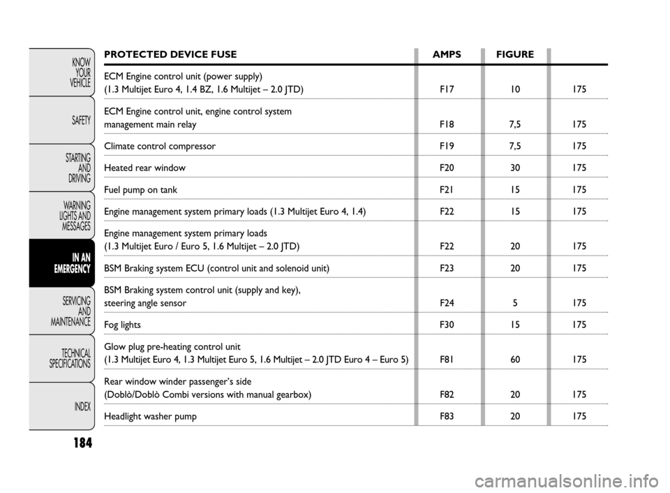
INDEXPROTECTED DEVICE FUSE AMPS FIGURE
ECM Engine control unit (power supply)
(1.3 Multijet Euro 4, 1.4 BZ, 1.6 Multijet – 2.0 JTD) F17 10 175
ECM Engine control unit, engine control system
management main relay F18 7,5 175
Climate control compressor F19 7,5 175
Heated rear window F20 30 175
Fuel pump on tank F21 15 175
Engine management system primary loads (1.3 Multijet Euro 4, 1.4) F22 15 175
Engine management system primary loads
(1.3 Multijet Euro / Euro 5, 1.6 Multijet – 2.0 JTD) F22 20 175
BSM Braking system ECU (control unit and solenoid unit) F23 20 175
BSM Braking system control unit (supply and key),
steering angle sensor F24 5 175
Fog lights F30 15 175
Glow plug pre-heating control unit
(1.3 Multijet Euro 4, 1.3 Multijet Euro 5, 1.6 Multijet – 2.0 JTD Euro 4 – Euro 5) F81 60 175
Rear window winder passenger’s side
(Doblò/Doblò Combi versions with manual gearbox) F82 20 175
Headlight washer pump F83 20 175
Page 212 of 274

211
KNOW
YOUR
VEHICLE
SAFETY
STARTING
AND
DRIVING
WARNING
LIGHTS AND
MESSAGES
IN AN
EMERGENCY
SERVICING
AND
MAINTENANCE
TECHNICAL
SPECIFICATIONS
INDEXRUBBER TUBES
As far as the brake system and fuel rubber hoses are con-
cerned, stick closely to the “Scheduled Servicing Plan” in
this section.
Ozone, high temperatures and a prolonged lack of fluid
in the system may cause hardening and cracking of the
tubes, which could result in leaks. Careful inspections are
therefore necessary.
WINDSCREEN/REAR WINDOW
WIPERS
(for versions/markets where provided)
BLADES
Regularly clean the rubber part using appropriate
products; TUTELA PROFESSIONAL SC 35 is recom-
mended.
Replace the blades if the rubber edge is deformed or worn.
In any event, it is advisable to replace them approximate-
ly once a year.
A few simple precautions can reduce the possibility of dam-
age to the blades:
❒make sure that the rubber part is not frozen to the wind-
screen in sub-zero temperatures. Use an antifreeze
product to release it if required;
❒remove any snow from the glass: in addition to pro-
tecting the blades, this prevents the electric motor from
overheating;
❒do not operate the windscreen and the rear window
wipers on dry glass.
Driving with worn wiper blades is a seri-
ous hazard, because visibility is reduced
in bad weather.
WARNING
Page 217 of 274
216
KNOW
YOUR
VEHICLE
SAFETY
STARTING
AND
DRIVING
WARNING
LIGHTS AND
MESSAGES
IN AN
EMERGENCY
SERVICING
AND
MAINTENANCE
TECHNICAL
SPECIFICATIONS
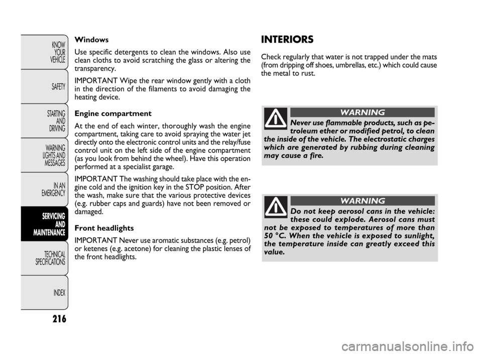
INDEXINTERIORS
Check regularly that water is not trapped under the mats
(from dripping off shoes, umbrellas, etc.) which could cause
the metal to rust. Windows
Use specific detergents to clean the windows. Also use
clean cloths to avoid scratching the glass or altering the
transparency.
IMPORTANT Wipe the rear window gently with a cloth
in the direction of the filaments to avoid damaging the
heating device.
Engine compartment
At the end of each winter, thoroughly wash the engine
compartment, taking care to avoid spraying the water jet
directly onto the electronic control units and the relay/fuse
control unit on the left side of the engine compartment
(as you look from behind the wheel). Have this operation
performed at a specialist garage.
IMPORTANT The washing should take place with the en-
gine cold and the ignition key in the STOP position. After
the wash, make sure that the various protective devices
(e.g. rubber caps and guards) have not been removed or
damaged.
Front headlights
IMPORTANT Never use aromatic substances (e.g. petrol)
or ketenes (e.g. acetone) for cleaning the plastic lenses of
the front headlights.
Never use flammable products, such as pe-
troleum ether or modified petrol, to clean
the inside of the vehicle. The electrostatic charges
which are generated by rubbing during cleaning
may cause a fire.
WARNING
Do not keep aerosol cans in the vehicle:
these could explode. Aerosol cans must
not be exposed to temperatures of more than
50 °C. When the vehicle is exposed to sunlight,
the temperature inside can greatly exceed this
value.
WARNING
Page 264 of 274
263
KNOW
YOUR
VEHICLE
SAFETY
STARTING
AND
DRIVING
WARNING
LIGHTS AND
MESSAGES
IN AN
EMERGENCY
SERVICING
AND
MAINTENANCE
TECHNICAL
SPECIFICATIONS
INDEX
CODE card .............................. 5
Control buttons..................... 70
Coolant overheating
warning light .......................145
Cruise Control....................... 63
Dashboard ................................ 3
Dead lock ................................. 8
Defrosting/demisting
– rear window ......... 46-49-58
– windscreen and front
side windows ........ 45-48-57
Demisting/defrosting
– rear window ......... 46-49-58
– windscreen and front
side windows............... 45-49
– door mirrors ......... 46-49-58
Diesel filter............................ 206
– light warning of water
in filter.............................. 151
Digital display ......................... 14– control buttons ................ 14
– setup menu ....................... 15
– standard screen ............... 14
Dipped beam headlights
– bulb replacement ........... 173
– switching on ...................... 59
Direction Indicators
– front bulb
replacement .................... 173
– rear bulb
replacement ...........175-176
– side bulb
replacement .................... 173
– switching on ...................... 60
Door locking ......................... 77
Doors
– central locking................... 77
– child safety device............. 80
– load area unlocking .......... 77
– locking/unlocking from
the inside......................79-80 – interiors ........................... 216
– leather upholstery ......... 217
– plastic parts .................... 217
– windows............................. 61
Cleaning your vehicle
– engine compartment .... 216
– exterior............................ 214
– interior ............................ 216
Climate control system
controls ..........................47-51
Climate control vents .......... 43
Climate control ............... 47-51
– air vents ...............................43
Clock
– adjusting ...............................22
Clutch
– technical
specifications................... 224
CO
2emissions
in exhaust ........................... 253
CO
2in exhaust .....................253