technical specifications FIAT DOBLO COMBI 2012 Owner handbook (in English)
[x] Cancel search | Manufacturer: FIAT, Model Year: 2012, Model line: DOBLO COMBI, Model: FIAT DOBLO COMBI 2012Pages: 283, PDF Size: 6.31 MB
Page 170 of 283
166
KNOWYOUR
VEHICLE
SAFETY
STARTING AND
DRIVING
WARNING
LIGHTS AND MESSAGES
IN AN
EMERGENCY
SERVICING AND
MAINTENANCE
TECHNICAL
SPECIFICA TIONS
INDEX
F0V0096mfig. 144F0V0097mfig. 145
❒ if in this case a pressure of at least 1.8 bar is not reached
within five minutes of switching on the compressor, do
not continue driving because the tyre is too damaged
and the hold cannot be guaranteed. Contact
a Fiat Dealership
❒ if you do reach the tyre pressure specified in the “Cold
tyre pressures” paragraph of the “Technical specifica-
tions” section, continue your journey immediately;
❒
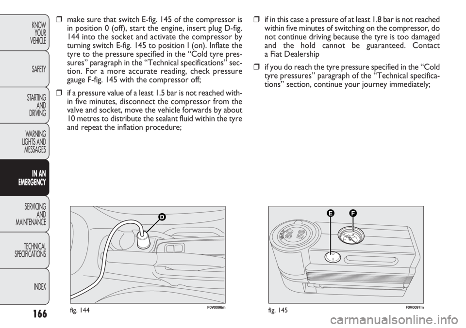
make sure that switch E-fig. 145 of the compressor is
in position 0 (off), start the engine, insert plug D-fig.
144 into the socket and activate the compressor by
turning switch E-fig. 145 to position I (on). Inflate the
tyre to the pressure specified in the “Cold tyre pres-
sures” paragraph in the “Technical specifications” sec-
tion. For a more accurate reading, check pressure
gauge F-fig. 145 with the compressor off;
❒ if a pressure value of a least 1.5 bar is not reached with-
in five minutes, disconnect the compressor from the
valve and socket, move the vehicle forwards by about
10 metres to distribute the sealant fluid within the tyre
and repeat the inflation procedure;
Page 171 of 283
167
KNOW
YOUR
VEHICLE
SAFETY
STARTING
AND
DRIVING
WARNING
LIGHTS AND
MESSAGES
IN AN
EMERGENCY
SERVICING
AND
MAINTENANCE
TECHNICAL
SPECIFICATIONS
INDEX
F0V0098mfig. 146
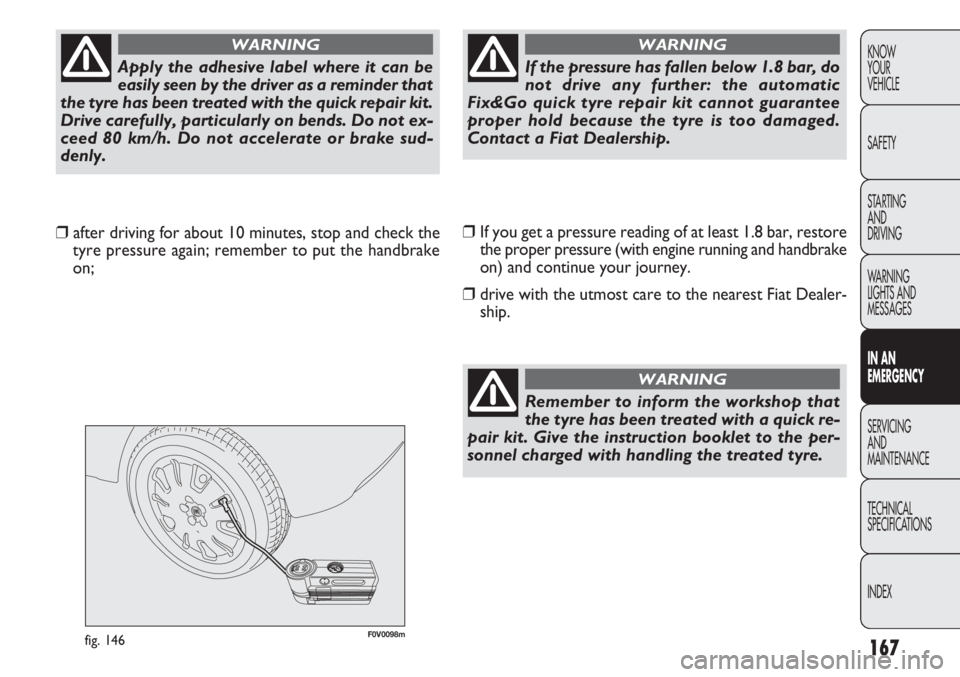
❒ If you get a pressure reading of at least 1.8 bar, restore
the proper pressure (with engine running and handbrake
on) and continue your journey.
❒ drive with the utmost care to the nearest Fiat Dealer-
ship.
❒
after driving for about 10 minutes, stop and check the
tyre pressure again; remember to put the handbrake
on;
Apply the adhesive label where it can be
easily seen by the driver as a reminder that
the tyre has been treated with the quick repair kit.
Drive carefully, particularly on bends. Do not ex-
ceed 80 km/h. Do not accelerate or brake sud-
denly.
WARNING
If the pressure has fallen below 1.8 bar, do
not drive any further: the automatic
Fix&Go quick tyre repair kit cannot guarantee
proper hold because the tyre is too damaged.
Contact a Fiat Dealership.
WARNING
Remember to inform the workshop that
the tyre has been treated with a quick re-
pair kit. Give the instruction booklet to the per-
sonnel charged with handling the treated tyre.
WARNING
Page 173 of 283
169
KNOW
YOUR
VEHICLE
SAFETY
STARTING
AND
DRIVING
WARNING
LIGHTS AND
MESSAGES
IN AN
EMERGENCY
SERVICING
AND
MAINTENANCE
TECHNICAL
SPECIFICATIONS
INDEXCHANGING A BULB
GENERAL INSTRUCTIONS
❒ Before changing a bulb, check the contacts for rusting;
❒ burnt-out bulbs must be replaced by others of the same
type and wattage;
❒ always check the direction of the beam after changing
a headlight bulb;
❒ when a light is not working, check that the corre-
sponding fuse is intact before changing the bulb. For the
location of fuses, refer to the “Changing a fuse” para-
graph in this section.
Changes or repairs to the electrical system
carried out incorrectly and without due
consideration for the technical specifications of
the system can lead to malfunctioning and gen-
erate a fire hazard.
WARNING
Halogen lamps contain pressurised gas. If
they break, glass fragments could fly every-
where.
WARNING
Touch only the metal part of a halogen
lamp. Touching the transparent part of the
bulb with your fingers may reduce the in-
tensity of the emitted light and even reduce the
lifespan of the bulb. If you do touch it accidental-
ly, rub the bulb with an alcohol-soaked cloth and
leave to dry.
If possible, we recommend that you let
a Fiat Dealership replace the bulbs. Prop-
er operation and orientation of the exter-
nal lights are essential for driving safety and com-
plying with the law.
IMPORTANT The internal surface of the light may appear
slightly misty: this does not indicate a fault, and is actually
caused by low temperature and the degree of humidity
in the air. Misting will rapidly disappear when the head-
lights are switched on. The presence of drops inside the
headlights indicates infiltration of water. Go to a Fiat Deal-
ership.
Page 175 of 283
171
KNOW
YOUR
VEHICLE
SAFETY
STARTING
AND
DRIVING
WARNING
LIGHTS AND
MESSAGES
IN AN
EMERGENCY
SERVICING
AND
MAINTENANCE
TECHNICAL
SPECIFICATIONS
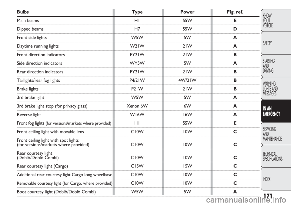
INDEXBulbs TypePowerFig. ref.
Main beams H155W E
Dipped beams H755W D
Front side lights W5W5WA
Daytime running lights W21W21WA
Front direction indicators PY21W21WB
Side direction indicators WY5W5WA
Rear direction indicators PY21W21WB
Taillights/rear fog lights P4/21W4W/21W B
Brake lights P21W21WB
3rd brake light W5W5WA
3rd brake light stop (for privacy glass) Xenon 6W6WA
Reverse light W16W16WA
Front fog lights (for versions/markets where provided)H155W E
Front ceiling light with movable lens C10W10WC
Front ceiling light with spot lights
(for versions/markets where provided) C10W10WC
Rear courtesy light
(Doblò/Doblò Combi) C10W10WC
Rear courtesy light (Cargo) C15W15WC
Additional rear courtesy light Cargo long wheelbaseC10W 10WC
Removable courtesy light (for Cargo, where provided)C10W 10WC
Boot courtesy light (Doblò/Doblò Combi) W5W5WA
Page 177 of 283
173
KNOW
YOUR
VEHICLE
SAFETY
STARTING
AND
DRIVING
WARNING
LIGHTS AND
MESSAGES
IN AN
EMERGENCY
SERVICING
AND
MAINTENANCE
TECHNICAL
SPECIFICATIONS
INDEX
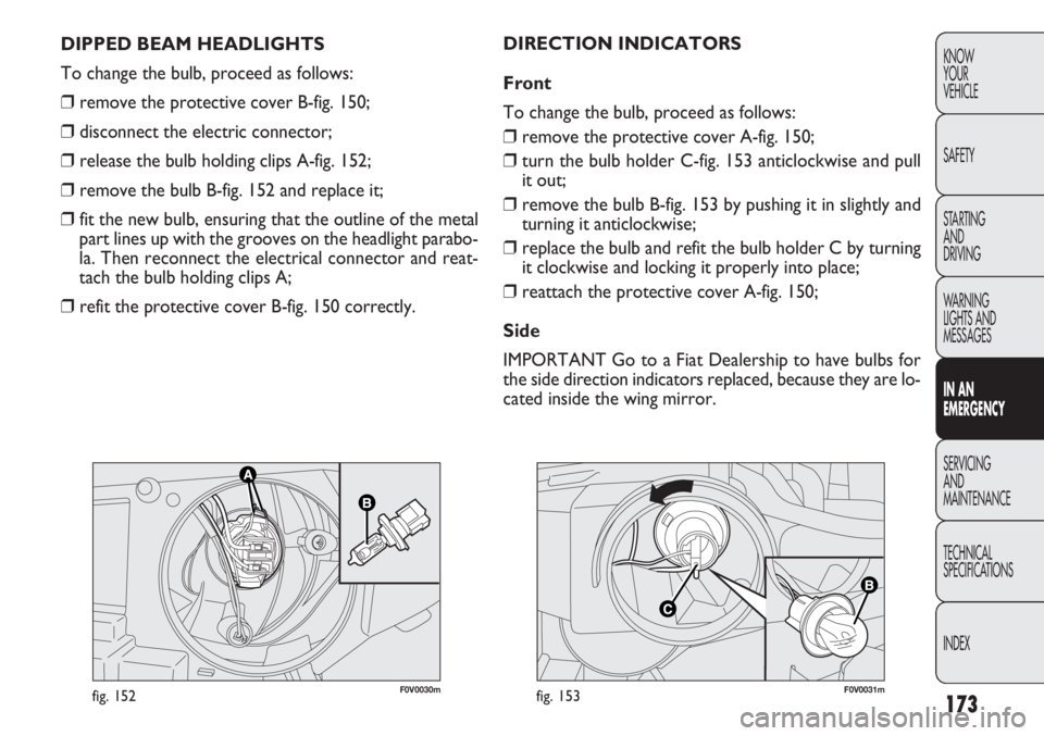
F0V0030mfig. 152F0V0031mfig. 153
DIRECTION INDICATORS
Front
To change the bulb, proceed as follows:
❒ remove the protective cover A-fig. 150;
❒ turn the bulb holder C-fig. 153 anticlockwise and pull
it out;
❒ remove the bulb B-fig. 153 by pushing it in slightly and
turning it anticlockwise;
❒ replace the bulb and refit the bulb holder C by turning
it clockwise and locking it properly into place;
❒ reattach the protective cover A-fig. 150;
Side
IMPORTANT Go to a Fiat Dealership to have bulbs for
the side direction indicators replaced, because they are lo-
cated inside the wing mirror.
DIPPED BEAM HEADLIGHTS
To change the bulb, proceed as follows:
❒
remove the protective cover B-fig. 150;
❒ disconnect the electric connector;
❒ release the bulb holding clips A-fig. 152;
❒ remove the bulb B-fig. 152 and replace it;
❒ fit the new bulb, ensuring that the outline of the metal
part lines up with the grooves on the headlight parabo-
la. Then reconnect the electrical connector and reat-
tach the bulb holding clips A;
❒ refit the protective cover B-fig. 150 correctly.
Page 179 of 283
175
KNOW
YOUR
VEHICLE
SAFETY
STARTING
AND
DRIVING
WARNING
LIGHTS AND
MESSAGES
IN AN
EMERGENCY
SERVICING
AND
MAINTENANCE
TECHNICAL
SPECIFICATIONS
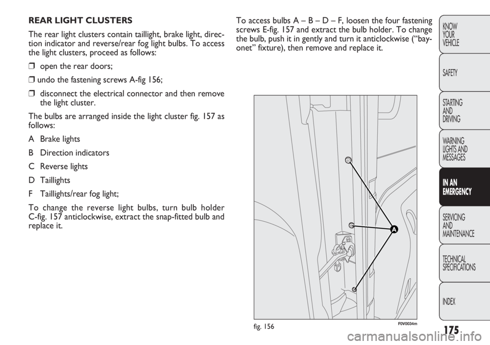
INDEXTo access bulbs A – B – D – F, loosen the four fastening
screws E-fig. 157 and extract the bulb holder. To change
the bulb, push it in gently and turn it anticlockwise (“bay-
onet” fixture), then remove and replace it.
REAR LIGHT CLUSTERS
The rear light clusters contain taillight, brake light, direc-
tion indicator and reverse/rear fog light bulbs. To access
the light clusters, proceed as follows:
❒
open the rear doors;
❒ undo the fastening screws A-fig 156;
❒ disconnect the electrical connector and then remove
the light cluster.
The bulbs are arranged inside the light cluster fig. 157 as
follows:
A Brake lights
B Direction indicators
C Reverse lights
D Taillights
F Taillights/rear fog light;
To change the reverse light bulbs, turn bulb holder
C-fig. 157 anticlockwise, extract the snap-fitted bulb and
replace it.
F0V0034mfig. 156
Page 181 of 283
177
KNOW
YOUR
VEHICLE
SAFETY
STARTING
AND
DRIVING
WARNING
LIGHTS AND
MESSAGES
IN AN
EMERGENCY
SERVICING
AND
MAINTENANCE
TECHNICAL
SPECIFICATIONS
INDEX
F0V0037mfig. 161
F0V0179mfig. 160
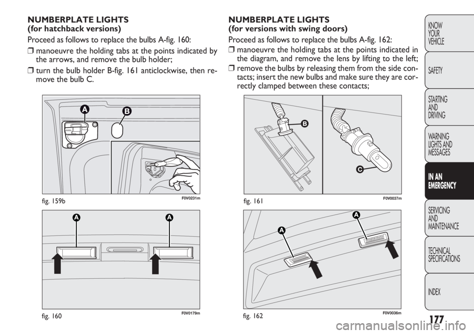
NUMBERPLATE LIGHTS
(for versions with swing doors)
Proceed as follows to replace the bulbs A-fig. 162:
❒ manoeuvre the holding tabs at the points indicated in
the diagram, and remove the lens by lifting to the left;
❒ remove the bulbs by releasing them from the side con-
tacts; insert the new bulbs and make sure they are cor-
rectly clamped between these contacts;
NUMBERPLATE LIGHTS
(for hatchback versions)
Proceed as follows to replace the bulbs A-fig. 160:
❒
manoeuvre the holding tabs at the points indicated by
the arrows, and remove the bulb holder;
❒ turn the bulb holder B-fig. 161 anticlockwise, then re-
move the bulb C.
F0V0036mfig. 162
F0V0231mfig. 159b
Page 183 of 283
179
KNOW
YOUR
VEHICLE
SAFETY
STARTING
AND
DRIVING
WARNING
LIGHTS AND
MESSAGES
IN AN
EMERGENCY
SERVICING
AND
MAINTENANCE
TECHNICAL
SPECIFICATIONS
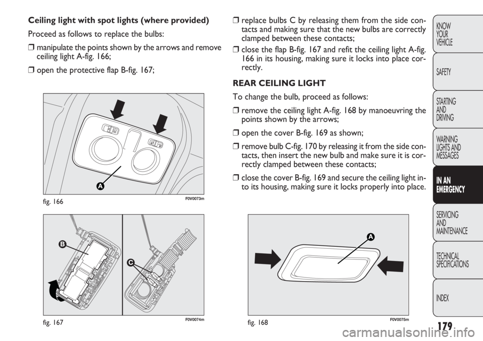
INDEX❒ replace bulbs C by releasing them from the side con-
tacts and making sure that the new bulbs are correctly
clamped between these contacts;
❒ close the flap B-fig. 167 and refit the ceiling light A-fig.
166 in its housing, making sure it locks into place cor-
rectly.
REAR CEILING LIGHT
To change the bulb, proceed as follows:
❒ remove the ceiling light A-fig. 168 by manoeuvring the
points shown by the arrows;
❒ open the cover B-fig. 169 as shown;
❒ remove bulb C-fig. 170 by releasing it from the side con-
tacts, then insert the new bulb and make sure it is cor-
rectly clamped between these contacts;
❒ close the cover B-fig. 169 and secure the ceiling light in-
to its housing, making sure it locks properly into place.
Ceiling light with spot lights (where provided)
Proceed as follows to replace the bulbs:
❒
manipulate the points shown by the arrows and remove
ceiling light A-fig. 166;
❒ open the protective flap B-fig. 167;
F0V0074mfig. 167
F0V0073mfig. 166
F0V0075mfig. 168
Page 185 of 283
181
KNOW
YOUR
VEHICLE
SAFETY
STARTING
AND
DRIVING
WARNING
LIGHTS AND
MESSAGES
IN AN
EMERGENCY
SERVICING
AND
MAINTENANCE
TECHNICAL
SPECIFICATIONS
INDEX
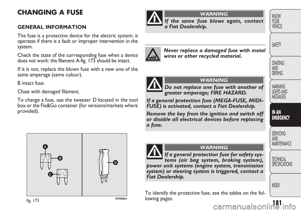
F0V0088mfig. 173
CHANGING A FUSE
GENERAL INFORMATION
The fuse is a protective device for the electric system: it
operates if there is a fault or improper intervention in the
system.
Check the state of the corresponding fuse when a device
does not work: the filament A-fig. 173 should be intact.
If it is not, replace the blown fuse with a new one of the
same amperage (same colour).
B intact fuse.
Cfuse with damaged filament.
To change a fuse, use the tweezer D located in the tool
box or the Fix&Go container (for versions/markets where
provided).
If the same fuse blows again, contact
a Fiat Dealership.
WARNING
Never replace a damaged fuse with metal
wires or other recycled material.
Do not replace one fuse with another of
greater amperage; FIRE HAZARD.
If a general protection fuse (MEGA-FUSE, MIDI-
FUSE) is activated, contact a Fiat Dealership.
Remove the key from the ignition and switch off
or disable all electrical devices before replacing
a fuse.
WARNING
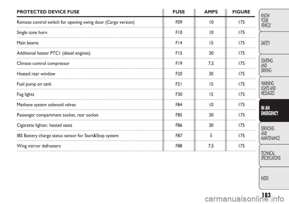
To identify the protective fuse, see the tables on the fol-
lowing pages.
If a general protection fuse for safety sys-
tems (air bag system, braking system),
power unit systems (engine system, transmission
system) or steering system is triggered, contact a
Fiat Dealership.
WARNING
Page 187 of 283
183
KNOW
YOUR
VEHICLE
SAFETY
STARTING
AND
DRIVING
WARNING
LIGHTS AND
MESSAGES
IN AN
EMERGENCY
SERVICING
AND
MAINTENANCE
TECHNICAL
SPECIFICATIONS
INDEXPROTECTED DEVICE FUSE FUSE AMPS FIGURE
Remote control switch for opening swing door (Cargo version) F0910175
Single tone horn F1010175
Main beams F1415175
Additional heater PTC1 (diesel engines) F1530175
Climate control compressor F197,5175
Heated rear window F2030175
Fuel pump on tank F2115175
Fog lights F3015175
Methane system solenoid valves F8410175
Passenger compartment socket, rear socket F8530175
Cigarette lighter, heated seats F8630175
IBS Battery charge status sensor for Start&Stop system F875175
Wing mirror defrosters F887,5175