technical specifications FIAT DOBLO COMBI 2012 Owner handbook (in English)
[x] Cancel search | Manufacturer: FIAT, Model Year: 2012, Model line: DOBLO COMBI, Model: FIAT DOBLO COMBI 2012Pages: 283, PDF Size: 6.31 MB
Page 117 of 283
113
KNOW
YOUR
VEHICLE
SAFETY
STAR
TING
AND
DRIVING
WARNING
LIGHTS AND
MESSAGES
IN AN
EMERGENCY
SERVICING
AND
MAINTENANCE
TECHNICAL
SPECIFICATIONS
INDEX
PROTECTING THE ENVIRONMENT
The devices for reducing petrol engine emissions are the
following:
❒three-way catalytic converter;
❒Lambda sensors;
❒evaporation prevention system.
In addition, do not let the engine run, even for a test, with
one or more spark plugs disconnected.
The following devices are used for reducing diesel fuel en-
gine emissions:
❒oxidising catalytic converter;
❒exhaust gas recirculation system (EGR);
❒diesel particulate filter (DPF) (for versions/markets
where provided).
To close
1) Fit the cap (complete with key) and turn it clockwise
until it clicks once or more.
2) Turn the key clockwise and extract it, then close the
flap.
The hermetic seal may cause a slight increase in pressure
in the tank. A suction noise when you release the cap is
therefore entirely normal.
Do not place naked flames or lit cigarettes
near to the fuel tank opening: fire risk. Keep
your face away from the fuel tank open-
ing to avoid breathing in harmful vapours.
Page 118 of 283
114
KNOWYOUR
VEHICLE
SAFETY
ST AR
TING AND
DRIVING
WARNING
LIGHTS AND MESSAGES
IN AN
EMERGENCY
SERVICING AND
MAINTENANCE
TECHNICAL
SPECIFICATIONS
INDEX
DIESEL PARTICULATE FILTER (DPF)
(for versions/markets where provided)
The Diesel Particulate Filter is a mechanical filter, inte-
gral with the exhaust system, that physically traps carbon
particles present in the exhaust gases of Diesel engines.
It is needed to eliminate almost all carbon particles in com-
pliance with current/future legislation. During normal use
of the vehicle, the engine management control unit records
a set of data (e.g. journey time, type of route, tempera-
tures, etc.) and it will then calculate how much particu-
late has been trapped by the filter. Since the filter is a collecting system, it should be regular-
ly regenerated (cleaned) by burning the carbon particles.
The regeneration procedure is controlled automatically by
the engine management control unit according to the fil-
ter conditions and vehicle use conditions.
During regeneration, the following may occur: a limited in-
crease in the engine speed, activation of the fan, a limited
increase in fumes and high temperatures at the exhaust.
These are not faults; they do not impair vehicle perfor-
mance or damage the environment. If the dedicated mes-
sage is displayed, refer to the “Warning lights and mes-
sages” section.
Page 133 of 283
129
KNOW
YOUR
VEHICLE
SAFETY
STARTING
AND
DRIVING
WARNING
LIGHTS AND
MESSAGES
IN AN
EMERGENCY
SERVICING
AND
MAINTENANCE
TECHNICAL
SPECIFICATIONS
INDEX
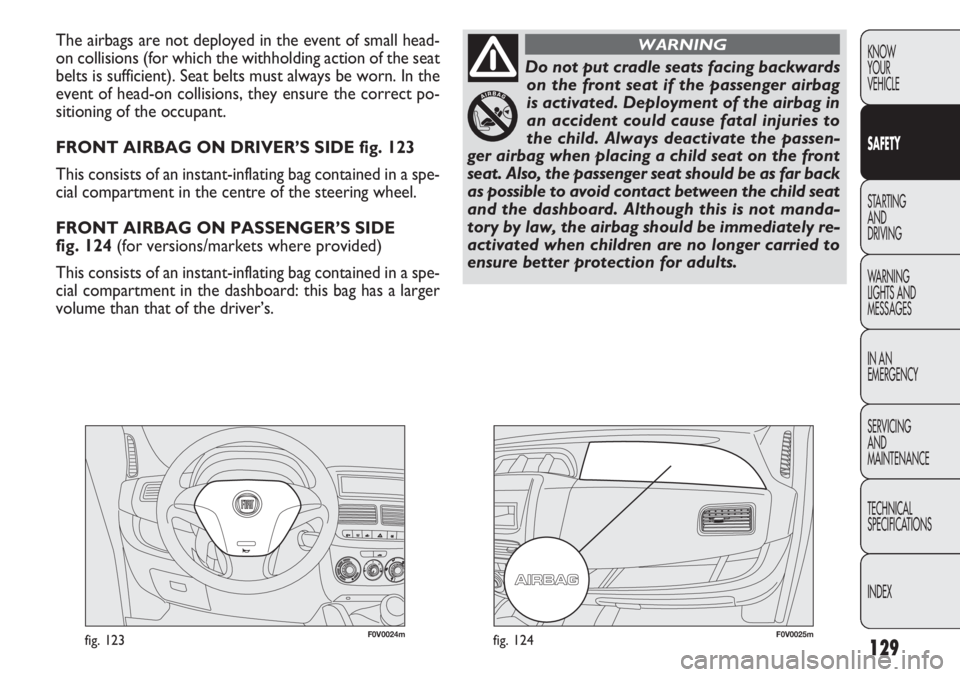
F0V0024mfig. 123F0V0025mfig. 124
The airbags are not deployed in the event of small head-
on collisions (for which the withholding action of the seat
belts is sufficient). Seat belts must always be worn. In the
event of head-on collisions, they ensure the correct po-
sitioning of the occupant.
FRONT AIRBAG ON DRIVER’S SIDE fig. 123
This consists of an instant-inflating bag contained in a spe-
cial compartment in the centre of the steering wheel.
FRONT AIRBAG ON PASSENGER’S SIDE
fig. 124 (for versions/markets where provided)
This consists of an instant-inflating bag contained in a spe-
cial compartment in the dashboard: this bag has a larger
volume than that of the driver’s.
Do not put cradle seats facing backwardson the front seat if the passenger airbag
is activated. Deployment of the airbag in
an accident could cause fatal injuries to
the child. Always deactivate the passen-
ger airbag when placing a child seat on the front
seat. Also, the passenger seat should be as far back
as possible to avoid contact between the child seat
and the dashboard. Although this is not manda-
tory by law, the airbag should be immediately re-
activated when children are no longer carried to
ensure better protection for adults.
WARNING
Page 144 of 283
140
KNOWYOUR
VEHICLE
SAFETY
ST ARTING
AN
D
DRIVING
WARNING
LIGHTS AND MESSAGES
IN AN
EMERGENCY
SERVICING AND
MAINTENANCE
TECHNICAL
SPECIFICA TIONS
INDEX
SNOW TYRES
A Fiat Dealership will be happy to provide advice con-
cerning the most suitable type of tyre for the customer’s
requirements.
For the type, pressures and specifications of the snow tyre
to be used, follow carefully the instructions given in the
“Wheels” paragraph of the “Technical specifications” sec-
tion.
The winter performance of these tyres is considerably re-
duced when the tread thickness is less than 4 mm. If this
is the case, replace them.
Due to their specific features, the performance of snow
tyres is much lower than that of standard tyres in normal
conditions or on long motorway stretches. You should
therefore use them only in the conditions for which they
were designed.
IMPORTANT When using snow tyres with a maximum
speed index below the one that can be reached by the
vehicle (increased by 5%), place a notice in the passenger
compartment, plainly in view, which states the maximum
speed allowed by the snow tyres (as per EC Directive).
All four tyres should be the same (brand and profile) to
ensure greater safety when driving and braking as well as
making the car more responsive.
Remember that you should not change the rotation di-
rection of the tyres.The ABS with which the vehicle may be
equipped will not control the braking sys-
tem of the trailer. Particular caution is therefore
required on slippery roads.
WARNING
Never modify the braking system of the ve-
hicle to control the trailer brake. The trail-
er braking system must be fully independent from
the hydraulic system of the vehicle.
WARNING
Page 159 of 283
155
KNOW
YOUR
VEHICLE
SAFETY
STARTING
AND
DRIVING
WARNING
LIGHTS AND
MESSAGES
IN AN
EMERGENCY
SERVICING
AND
MAINTENANCE
TECHNICAL
SPECIFICATIONS
INDEX
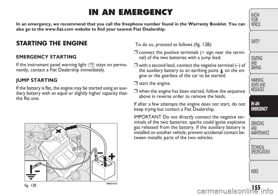
F0V0147mfig. 128
STARTING THE ENGINE
EMERGENCY STARTING
If the instrument panel warning light
Ystays on perma-
nently, contact a Fiat Dealership immediately.
JUMP STARTING
If the battery is flat, the engine may be started using an aux-
iliary battery with an equal or slightly higher capacity than
the flat one.
IN AN EMERGENCY
In an emergency, we recommend that you call the freephone number found i\
n the Warranty Booklet. You can
also go to the www.fiat.com website to find your nearest Fiat Dealership\
.
To do so, proceed as follows (fig. 128):
❒ connect the positive terminals (+ sign near the termi-
nal) of the two batteries with a jump lead;
❒ with a second lead, connect the negative terminal (–) of
the auxiliary battery to an earthing point E on the en-
gine or the gearbox of the car to be started;
❒ start the engine.
❒ when the engine has been started, follow the sequence
above in reverse order to remove the leads.
If after a few attempts the engine does not start, do not
keep trying but contact a Fiat Dealership.
IMPORTANT Do not directly connect the negative ter-
minals of the two batteries: sparks could ignite explosive
gas released from the battery. If the auxiliary battery is
installed on another vehicle, prevent accidental contact be-
tween metallic parts of the two vehicles.
Page 161 of 283
157
KNOW
YOUR
VEHICLE
SAFETY
STARTING
AND
DRIVING
WARNING
LIGHTS AND
MESSAGES
IN AN
EMERGENCY
SERVICING
AND
MAINTENANCE
TECHNICAL
SPECIFICATIONS
INDEXUse your hazard lights, warning triangle,
etc to show that your car is stationary.
Passengers should get out of the car, particularly
if it is heavily loaded, and wait for the wheel to be
changed away from the traffic. If you are on a
steep slope or uneven surface, place wedges or
other suitable objects under the wheels to secure
the vehicle. Repair and refit the standard wheel
as soon as possible. Do not grease the bolt threads
before you fit them, because they could sudden-
ly come loose.
WARNING
Use the jack only to replace wheels on the
vehicle with which it is supplied or on oth-
er vehicles of the same model. Never use the jack
for other purposes, such as lifting other models.
Never use the jack to carry out repairs under the
vehicle. Incorrect positioning of the jack may
cause the lifted vehicle to fall. Do not use the jack
for loads higher than the one shown on its label.
WARNING
Incorrect hub cap assembly may cause it
to come off when the car is moving. Nev-
er tamper with the inflation valve. Never intro-
duce tools of any kind between the rim and the
tyre. Check tyre and spare wheel pressures regu-
larly, referring to the values shown in the “Tech-
nical specifications” section.
WARNING
Note for one-way tyres
One-way tyres have a few arrows on the side indicating
the rotation direction. If a wheel is changed (when punc-
tured, for example) the direction of the arrows on the spa-
re wheel tyre may not coincide with the rotation direc-
tion of the wheel to be replaced. In these conditions, too,
the tyre still maintains its safety features.
Anyway, it is recommended to have the wheel repaired
and refitted as soon as possible, as the best performance
is achieved when the rotation direction of all tyres coin-
cides with the one indicated by the arrows.
Page 163 of 283
159
KNOW
YOUR
VEHICLE
SAFETY
STARTING
AND
DRIVING
WARNING
LIGHTS AND
MESSAGES
IN AN
EMERGENCY
SERVICING
AND
MAINTENANCE
TECHNICAL
SPECIFICATIONS
INDEX
F0V0193mfig. 133
F0V0151mfig. 132
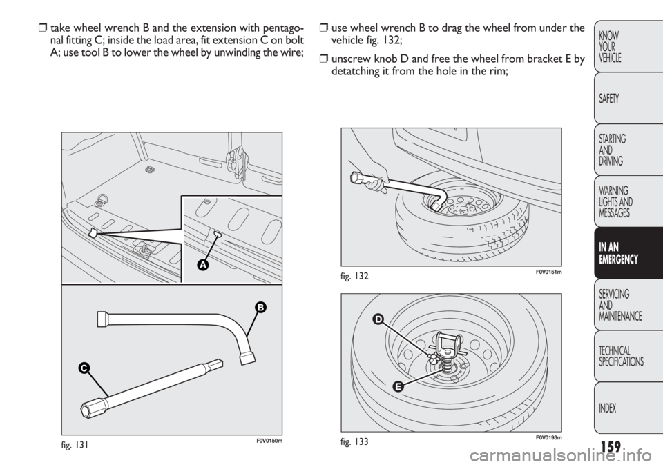
❒ use wheel wrench B to drag the wheel from under the
vehicle fig. 132;
❒ unscrew knob D and free the wheel from bracket E by
detatching it from the hole in the rim;
❒
take wheel wrench B and the extension with pentago-
nal fitting C; inside the load area, fit extension C on bolt
A; use tool B to lower the wheel by unwinding the wire;
BB
CC
F0V0150mfig. 131
Page 165 of 283
161
KNOW
YOUR
VEHICLE
SAFETY
STARTING
AND
DRIVING
WARNING
LIGHTS AND
MESSAGES
IN AN
EMERGENCY
SERVICING
AND
MAINTENANCE
TECHNICAL
SPECIFICATIONS
INDEX
F0V0156mfig. 137F0V0157mfig. 138
❒ loosen the fastening bolts completely and then remove
the wheel;
❒ make sure the contact surfaces between spare wheel
and hub are clean so that the fastening bolts will not
come loose;
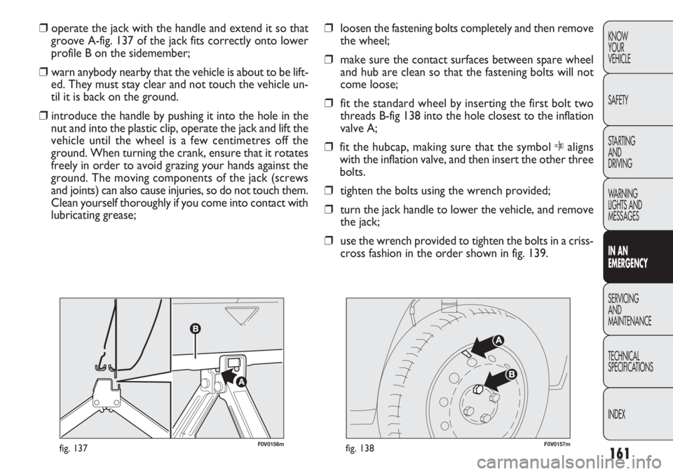
❒ fit the standard wheel by inserting the first bolt two
threads B-fig 138 into the hole closest to the inflation
valve A;
❒ fit the hubcap, making sure that the symbol Caligns
with the inflation valve, and then insert the other three
bolts.
❒ tighten the bolts using the wrench provided;
❒ turn the jack handle to lower the vehicle, and remove
the jack;
❒ use the wrench provided to tighten the bolts in a criss-
cross fashion in the order shown in fig. 139.
❒
operate the jack with the handle and extend it so that
groove A-fig. 137 of the jack fits correctly onto lower
profile B on the sidemember;
❒ warn anybody nearby that the vehicle is about to be lift-
ed. They must stay clear and not touch the vehicle un-
til it is back on the ground.
❒ introduce the handle by pushing it into the hole in the
nut and into the plastic clip, operate the jack and lift the
vehicle until the wheel is a few centimetres off the
ground. When turning the crank, ensure that it rotates
freely in order to avoid grazing your hands against the
ground. The moving components of the jack (screws
and joints) can also cause injuries, so do not touch them.
Clean yourself thoroughly if you come into contact with
lubricating grease;
Page 167 of 283
163
KNOW
YOUR
VEHICLE
SAFETY
STARTING
AND
DRIVING
WARNING
LIGHTS AND
MESSAGES
IN AN
EMERGENCY
SERVICING
AND
MAINTENANCE
TECHNICAL
SPECIFICATIONS
INDEXAutomatic FIX&GO QUICK TYRE
REPA I R KIT
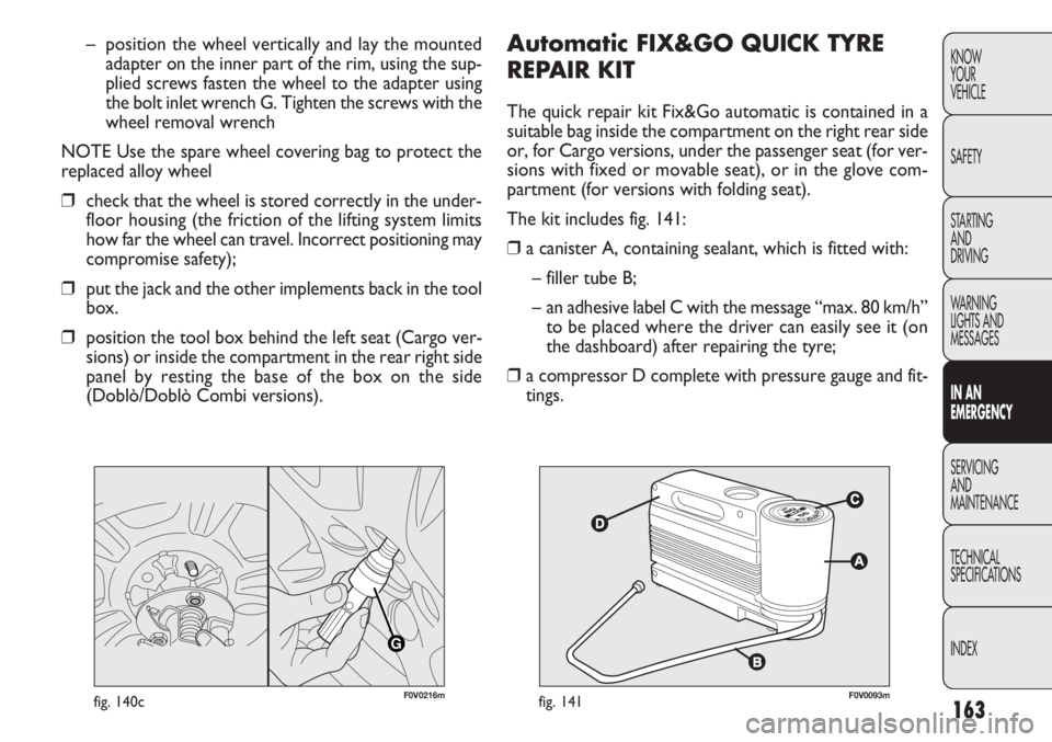
The quick repair kit Fix&Go automatic is contained in a
suitable bag inside the compartment on the right rear side
or, for Cargo versions, under the passenger seat (for ver-
sions with fixed or movable seat), or in the glove com-
partment (for versions with folding seat).
The kit includes fig. 141:
❒a canister A, containing sealant, which is fitted with:
– filler tube B;
– an adhesive label C with the message “max. 80 km/h” to be placed where the driver can easily see it (on
the dashboard) after repairing the tyre;
❒ a compressor D complete with pressure gauge and fit-
tings.
– position the wheel vertically and lay the mounted
adapter on the inner part of the rim, using the sup-
plied screws fasten the wheel to the adapter using
the bolt inlet wrench G. Tighten the screws with the
wheel removal wrench
NOTE Use the spare wheel covering bag to protect the
replaced alloy wheel
❒ check that the wheel is stored correctly in the under-
floor housing (the friction of the lifting system limits
how far the wheel can travel. Incorrect positioning may
compromise safety);
❒ put the jack and the other implements back in the tool
box.
❒ position the tool box behind the left seat (Cargo ver-
sions) or inside the compartment in the rear right side
panel by resting the base of the box on the side
(Doblò/Doblò Combi versions).
G
F0V0216mfig. 140cF0V0093mfig. 141
Page 169 of 283
165
KNOW
YOUR
VEHICLE
SAFETY
STARTING
AND
DRIVING
WARNING
LIGHTS AND
MESSAGES
IN AN
EMERGENCY
SERVICING
AND
MAINTENANCE
TECHNICAL
SPECIFICATIONS
INDEX
F0V0095mfig. 143
INFLATION PROCEDURE
If the wheel rim is damaged (the channel
is so deformed as to cause an air leakage)
it cannot be repaired. Do not remove foreign bod-
ies (screws or nails) from the tyre.
WARNING
The cylinder contains ethylene glycol. It
contains latex, which may cause an aller-
gic reaction. Harmful if swallowed. Irritates the
eyes. There could be a reaction in case of inhala-
tion or contact. Avoid contact with your eyes, skin
and clothes. In the event of contact, wash imme-
diately with plenty of water. Do not induce vom-
iting if swallowed. Rinse your mouth out and drink
plenty of water. Call a doctor immediately. Keep
out of the reach of children. The product must not
be used by asthmatics. Do not breathe in the
vapours during insertion and suction. Call a doc-
tor immediately if allergic reactions are noted.
Store the canister in its proper compartment,
away from sources of heat. The sealant has an ex-
piry date. Replace the cylinder if its sealant is out
of date.
WARNING
Put on the protective gloves provided with
the quick tyre repair kit.
WARNING
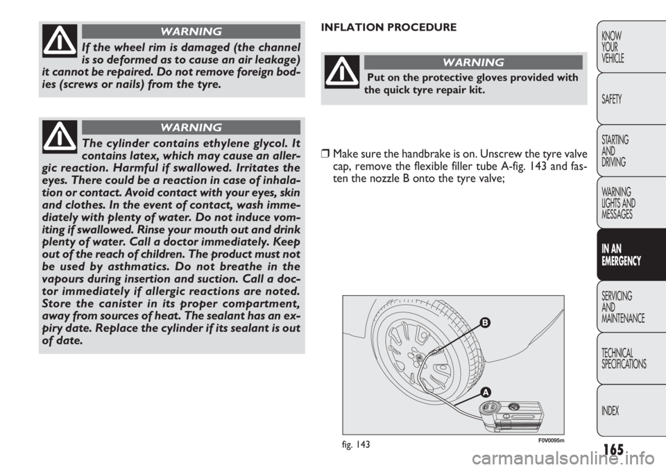
❒ Make sure the handbrake is on. Unscrew the tyre valve
cap, remove the flexible filler tube A-fig. 143 and fas-
ten the nozzle B onto the tyre valve;