technical specifications FIAT DOBLO COMBI 2012 Owner handbook (in English)
[x] Cancel search | Manufacturer: FIAT, Model Year: 2012, Model line: DOBLO COMBI, Model: FIAT DOBLO COMBI 2012Pages: 283, PDF Size: 6.31 MB
Page 107 of 283
103
KNOW
YOUR
VEHICLE
SAFETY
STAR
TING
AND
DRIVING
WARNING
LIGHTS AND
MESSAGES
IN AN
EMERGENCY
SERVICING
AND
MAINTENANCE
TECHNICAL
SPECIFICATIONS
INDEX
F0V0077mfig. 102
❒becomes continuous when the distance between the
vehicle and the obstacle is less than about 30 cm, and
stops immediately if the distance increases;
❒remains constant if the distance between the vehicle
and the obstacle remains unchanged.
FAILURE INDICATIONS
Parking sensor failures are indicated, when engaging re-
verse gear, by a three second beep.
PARKING SENSORS
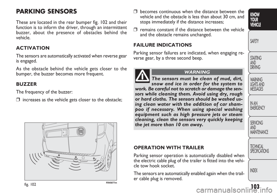
These are located in the rear bumper fig. 102 and their
function is to inform the driver, through an intermittent
buzzer, about the presence of obstacles behind the
vehicle.
ACTIVATION
The sensors are automatically activated when reverse gear
is engaged.
As the obstacle behind the vehicle gets closer to the
bumper, the buzzer becomes more frequent.
BUZZER
The frequency of the buzzer:
❒increases as the vehicle gets closer to the obstacle;
OPERATION WITH TRAILER
Parking sensor operation is automatically disabled when
the electric cable plug of the trailer is fitted into the vehi-
cle tow hook socket.
The sensors are automatically enabled again when the trail-
er cable plug is removed.
The sensors must be clean of mud, dirt,
snow and ice in order for the system to
work. Be careful not to scratch or damage the sen-
sors while cleaning them. Avoid using dry, rough
or hard cloths. The sensors should be washed us-
ing clean water with the addition of car sham-
poo if necessary. When using special washing
equipment such as high pressure jets or steam
cleaning, clean the sensors very quickly keeping
the jet more than 10 cm away.
WARNING
Page 108 of 283
F0V0040mfig. 103
START&STOP SYSTEM
FOREWORD
The Start&Stop device automatically stops the engine each
time the vehicle is stationary and starts it again when the
driver wants to move off.
This improves the efficiency of the vehicle by reducing fu-
el consumption, the emission of harmful gases and noise
pollution.
The system is activated each time the vehicle is started.
OPERATING MODES
Engine cut-out mode
WITH MANUAL TRANSMISSION
With the vehicle stationary, the engine cuts out with the
gearbox in neutral and the clutch pedal released.
104
KNOWYOUR
VEHICLE
SAFETY
ST AR
TING AND
DRIVING
WARNING
LIGHTS AND MESSAGES
IN AN
EMERGENCY
SERVICING AND
MAINTENANCE
TECHNICAL
SPECIFICATIONS
INDEX
GENERAL WARNINGS
❒When parking, pay special attention to obstacles that
may be set above or below the sensors.
❒Sometimes, objects located very near the rear of the
vehicle are not detected and could therefore damage
the vehicle or be damaged themselves.
❒The signals sent out by the sensors can be altered by
dirt, snow or ice deposited on the sensors or by ul-
trasound systems (e.g. truck pneumatic brakes or pneu-
matic drills) near the vehicle.
❒The parking sensors work properly with the swing
doors closed. If they are open, they can cause the sys-
tem to send false signals: always close the rear doors.
The ultimate responsibility when parking
and carrying out other dangerous ma-
noeuvres still rests with the driver. When park-
ing, make sure that no-one is standing in the area,
especially children or animals. Parking sensors are
designed to assist drivers; however, you must al-
ways concentrate fully during potentially danger-
ous manoeuvres, even if carried out at low speeds.
WARNING
Page 109 of 283
105
KNOW
YOUR
VEHICLE
SAFETY
STAR
TING
AND
DRIVING
WARNING
LIGHTS AND
MESSAGES
IN AN
EMERGENCY
SERVICING
AND
MAINTENANCE
TECHNICAL
SPECIFICATIONS
INDEX
WITH ROBOTISED GEARBOX
The engine cuts out if the vehicle stops with the brake ped-
al pressed.
This condition can be maintained even if the brake pedal
is not depressed, if the gear lever is in position N.
N.B.: The engine can only be stopped automatically after
a speed of about 10 Km/h is reached, to prevent the en-
gine from being repeatedly stopped when driving at walk-
ing pace.
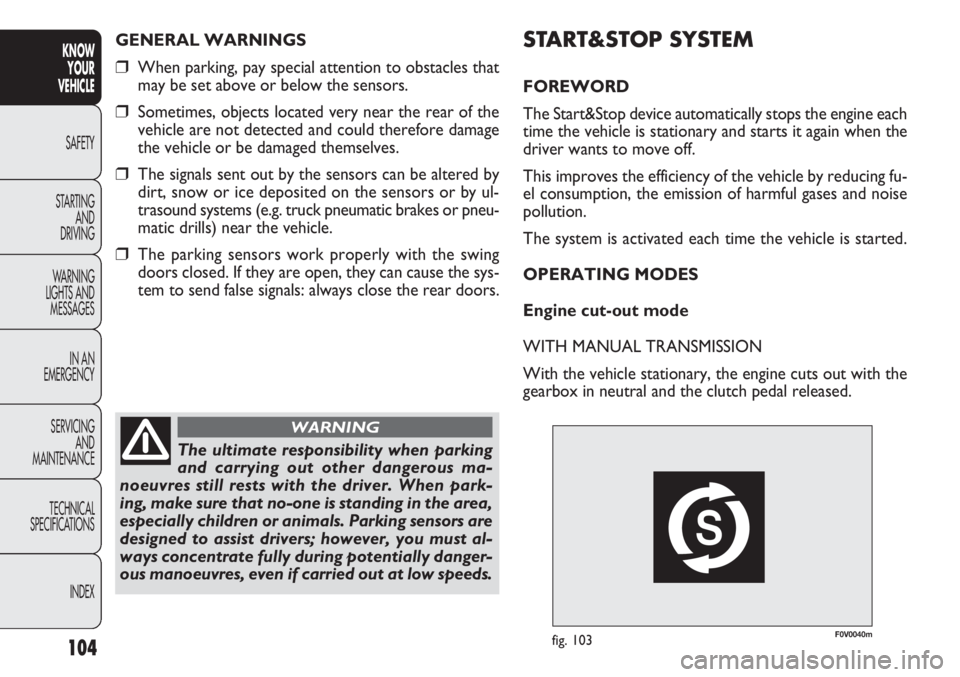
The engine being stopped is signalled by a symbol fig. 103
on the display, depending on the trim level.
Engine restarting mode
WITH NORMAL TRANSMISSION
Depress the clutch pedal to restart the engine.
WITH ROBOTIZED GEARBOX
If the gear lever is in position N, place it in any other gear,
otherwise release the brake pedal or move the gear le-
ver to (
+), (–) or R.
F0V0039mfig. 104
MANUAL ACTIVATION AND
DEACTIVATION
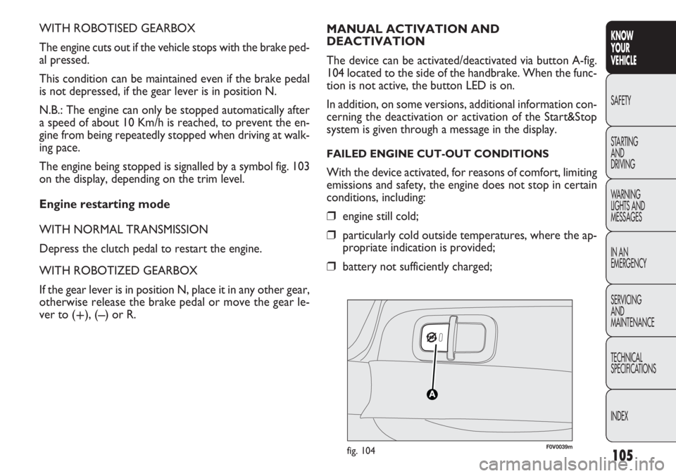
The device can be activated/deactivated via button A-fig.
104 located to the side of the handbrake. When the func-
tion is not active, the button LED is on.
In addition, on some versions, additional information con-
cerning the deactivation or activation of the Start&Stop
system is given through a message in the display.
FAILED ENGINE CUT-OUT CONDITIONS
With the device activated, for reasons of comfort, limiting
emissions and safety, the engine does not stop in certain
conditions, including:
❒engine still cold;
❒particularly cold outside temperatures, where the ap-
propriate indication is provided;
❒battery not sufficiently charged;
Page 110 of 283
❒vehicle in motion, for example when driving on hilly
roads;
❒stopping the engine through the Start&Stop system for
more than about three minutes.
❒automatic climate control system for establishing a
comfortable temperature or enabling the MAX – DEF
function.
With a gear engaged, the engine can only be automatical-
ly restarted by fully depressing the clutch pedal. The dri-
ver is asked to perform this operation through the warn-
ing light flashing in the instrument panel fig. 103 and, where
provided, the message in the display.
N.B.: If the clutch is not depressed when the three min-
utes have elapsed since the engine was stopped, the en-
gine can only be restarted using the key.
N.B.: If you stall the engine, for example by releasing off
the clutch pedal quickly with gear engaged, if the
Start&Stop system is activated, the engine can be restart-
ed by fully depressing the clutch pedal or by putting the
gear lever into neutral.
SAFETY FUNCTIONS
In engine cut-out conditions through the Start&Stop sys-
tem, if the driver unfastens his/her seat belt and opens the
driver’s side door or the passenger’s side door, the engine
can only be restarted using the key.
The driver is notified of this condition by a buzzer, through
the warning light flashing in the instrument panel fig. 103
and, where provided, by a message in the display.
106
KNOW YOUR
VEHICLE
SAFETY
ST AR
TING AND
DRIVING
WARNING
LIGHTS AND MESSAGES
IN AN
EMERGENCY
SERVICING AND
MAINTENANCE
TECHNICAL
SPECIFICATIONS
INDEX
❒heated rear windscreen on;
❒windscreen wipers working at maximum speed;
❒particulate filter regeneration in progress (diesel en-
gines only);
❒driver’s door not shut;
❒driver’s seat belt not fastened;
❒reverse gear engaged (for example, during parking ma-
noeuvres);
❒automatic climate control is on and a comfortable tem-
perature has not yet been reached or MAX – DEF func-
tion enabled.
❒during the first period of use, to initialise the system
In the above cases, the warning light flashes fig. 103 and,
where available, there is a message in the display.
RESTARTING CONDITIONS
For reasons of comfort, limiting pollutant emissions and
safety purposes, the power unit can restart automatically
without any action on behalf of the driver if certain con-
ditions are met, including:
❒battery not sufficiently charged;
❒windscreen wipers working at maximum speed;
❒reduced braking system vacuum, e.g. following the
brake pedal being pressed repeatedly;
Page 111 of 283
107
KNOW
YOUR
VEHICLE
SAFETY
STAR
TING
AND
DRIVING
WARNING
LIGHTS AND
MESSAGES
IN AN
EMERGENCY
SERVICING
AND
MAINTENANCE
TECHNICAL
SPECIFICATIONS
INDEX
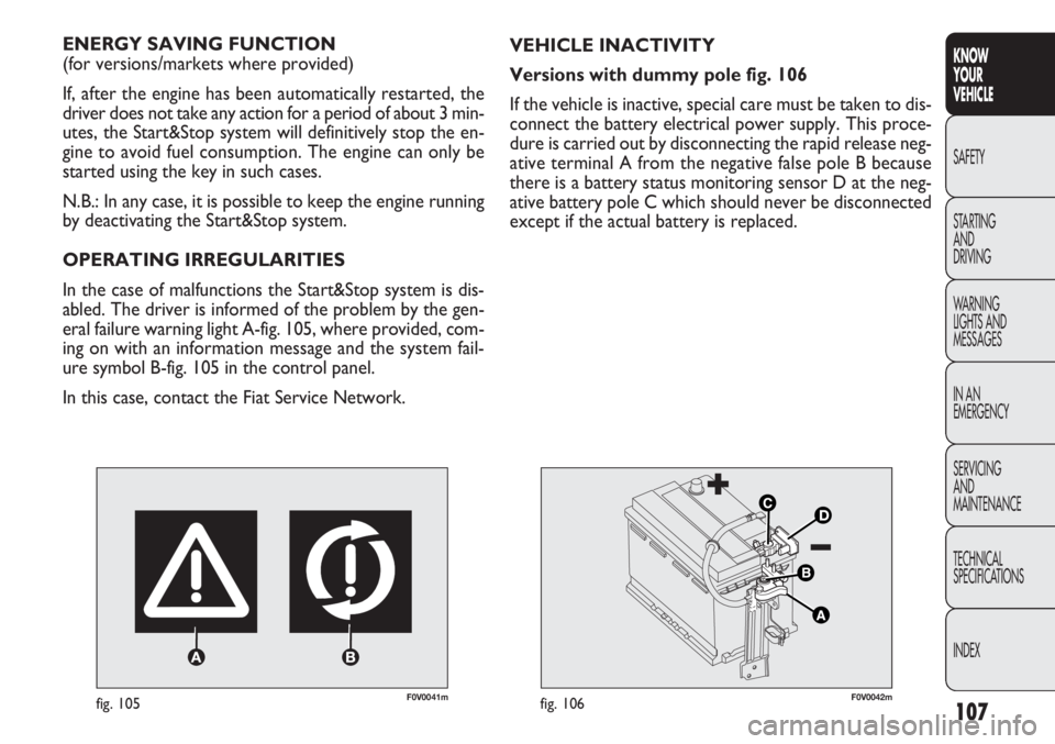
F0V0041mfig. 105
ENERGY SAVING FUNCTION
(for versions/markets where provided)
If, after the engine has been automatically restarted, the
driver does not take any action for a period of about 3 min-
utes, the Start&Stop system will definitively stop the en-
gine to avoid fuel consumption. The engine can only be
started using the key in such cases.
N.B.: In any case, it is possible to keep the engine running
by deactivating the Start&Stop system.
OPERATING IRREGULARITIES
In the case of malfunctions the Start&Stop system is dis-
abled. The driver is informed of the problem by the gen-
eral failure warning light A-fig. 105, where provided, com-
ing on with an information message and the system fail-
ure symbol B-fig. 105 in the control panel.
In this case, contact the Fiat Service Network. VEHICLE INACTIVITY
Versions with dummy pole fig. 106
If the vehicle is inactive, special care must be taken to dis-
connect the battery electrical power supply. This proce-
dure is carried out by disconnecting the rapid release neg-
ative terminal A from the negative false pole B because
there is a battery status monitoring sensor D at the neg-
ative battery pole C which should never be disconnected
except if the actual battery is replaced.
F0V0042mfig. 106
Page 112 of 283
108
KNOWYOUR
VEHICLE
SAFETY
ST AR
TING AND
DRIVING
WARNING
LIGHTS AND MESSAGES
IN AN
EMERGENCY
SERVICING AND
MAINTENANCE
TECHNICAL
SPECIFICATIONS
INDEX
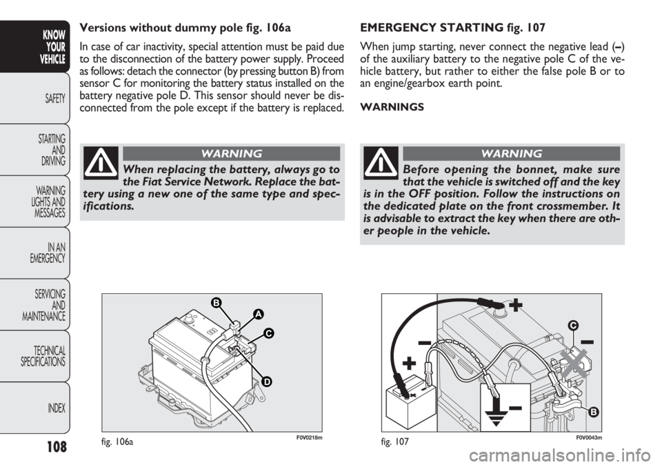
F0V0043mfig. 107
EMERGENCY STARTING fig. 107
When jump starting, never connect the negative lead ( –)
of the auxiliary battery to the negative pole C of the ve-
hicle battery, but rather to either the false pole B or to
an engine/gearbox earth point.
WARNINGS
When replacing the battery, always go to
the Fiat Service Network. Replace the bat-
tery using a new one of the same type and spec-
ifications.
WARNING
Before opening the bonnet, make sure
that the vehicle is switched off and the key
is in the OFF position. Follow the instructions on
the dedicated plate on the front crossmember. It
is advisable to extract the key when there are oth-
er people in the vehicle.
WARNING
F0V0218mfig. 106a
Versions without dummy pole fig. 106a
In case of car inactivity, special attention must be paid due
to the disconnection of the battery power supply. Proceed
as follows: detach the connector (by pressing button B) from
sensor C for monitoring the battery status installed on the
battery negative pole D. This sensor should never be dis-
connected from the pole except if the battery is replaced.
Page 113 of 283
109
KNOW
YOUR
VEHICLE
SAFETY
STAR
TING
AND
DRIVING
WARNING
LIGHTS AND
MESSAGES
IN AN
EMERGENCY
SERVICING
AND
MAINTENANCE
TECHNICAL
SPECIFICATIONS
INDEX
RADIO
(for versions/markets where provided)
For the operation of the radio with CD/MP3 player (for
versions/markets where provided), read the Supplement
attached to this Owner’s Handbook.
WIRING FOR LIGHTWEIGHT SYSTEM
The system consists of:
❒radio power cables;
❒front speaker cables (located on door mirror trims);
❒speaker cables on front door panels;
❒rear speaker cables (located next to the parcel shelf)
(for versions/markets where provided);
❒radio compartment;
❒aerial lead;
❒aerial.
WIRING FOR HEAVYWEIGHT SYSTEM
The system consists of:
❒radio power cables;
❒rear speaker cables (located next to the parcel shelf)
(for versions/markets where provided);
❒two tweeters on the door mirror trims;
❒two midwoofers on the lower part of the front doors;
The vehicle should always be evacuated
after the key has been removed or turned
to the OFF position. During refuelling operations,
it is necessary to make sure that the vehicle is off
with the ignition key in the OFF position.
WARNING
For vehicles with a robotised transmission,
if the engine cuts out automatically on
a gradient, it is advisable to restart the engine by
moving the gear lever towards (+) or (-) without
releasing the brake pedal. For vehicles with ro-
botised transmission, where the Hill Holder func-
tion is present, if the engine cuts out automati-
cally whilst on a hill, it is advisable to restart it
by moving the gear lever to (+) or (-) without re-
leasing the brake pedal to make the Hill Holder
function – which is only active when the engine
is running – available.
WARNING
If you want to prioritise climate comfort,
the Start&Stop system can be disabled to
allow continuous operation of the climate control
system.
WARNING
Page 114 of 283
110
KNOWYOUR
VEHICLE
SAFETY
ST AR
TING AND
DRIVING
WARNING
LIGHTS AND MESSAGES
IN AN
EMERGENCY
SERVICING AND
MAINTENANCE
TECHNICAL
SPECIFICATIONS
INDEX
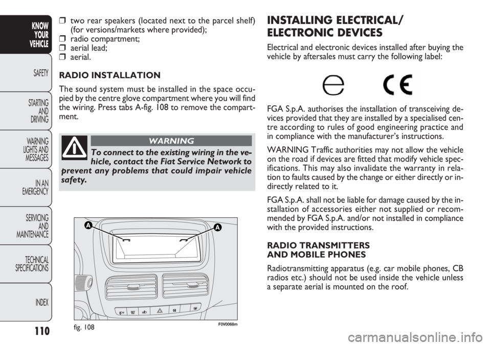
F0V0068mfig. 108
INSTALLING ELECTRICAL/
ELECTRONIC DEVICES
Electrical and electronic devices installed after buying the
vehicle by aftersales must carry the following label:
FGA S.p.A. authorises the installation of transceiving de-
vices provided that they are installed by a specialised cen-
tre according to rules of good engineering practice and
in compliance with the manufacturer’s instructions.
WARNING Traffic authorities may not allow the vehicle
on the road if devices are fitted that modify vehicle spec-
ifications. This may also invalidate the warranty in rela-
tion to faults caused by the change or either directly or in-
directly related to it.
FGA S.p.A. shall not be liable for damage caused by the in-
stallation of accessories either not supplied or recom-
mended by FGA S.p.A. and/or not installed in compliance
with the provided instructions.
RADIO TRANSMITTERS
AND MOBILE PHONES
Radiotransmitting apparatus (e.g. car mobile phones, CB
radios etc.) should not be used inside the vehicle unless
a separate aerial is mounted on the roof.
❒two rear speakers (located next to the parcel shelf)
(for versions/markets where provided);
❒radio compartment;
❒aerial lead;
❒aerial.
RADIO INSTALLATION
The sound system must be installed in the space occu-
pied by the centre glove compartment where you will find
the wiring. Press tabs A-fig. 108 to remove the compart-
ment.
To connect to the existing wiring in the ve-
hicle, contact the Fiat Service Network to
prevent any problems that could impair vehicle
safety.
WARNING
Page 115 of 283
111
KNOW
YOUR
VEHICLE
SAFETY
STAR
TING
AND
DRIVING
WARNING
LIGHTS AND
MESSAGES
IN AN
EMERGENCY
SERVICING
AND
MAINTENANCE
TECHNICAL
SPECIFICATIONS
INDEX
REFUELLING THE VEHICLE
PETROL ENGINES
Use unleaded petrol only, with an octane number (R.O.N.)
no lower than 95.
WARNING An inefficient catalytic silencer leads to harm-
ful exhaust emissions, thus contributing to air pollution.
WARNING Never use leaded petrol, even in small
amounts or in an emergency, as this would damage the
catalytic silencer beyond repair.
DIESEL ENGINES
Operation at low temperatures
If the outside temperature is very low, the diesel thick-
ens due to the formation of paraffin clots with consequent
defective operation of the fuel supply system.
In order to avoid these problems, different types of diesel
are distributed according to the season: summer type, win-
ter type and arctic type (cold/mountain areas). If refuelling
with diesel fuel whose specifications are not suitable for
the usage temperature, it is advisable to mix TUTELA
DIESEL ART additive in the proportions shown on the con-
tainer with the fuel. Pour the additive into the tank before
the fuel.
WARNING The use of similar devices inside the passen-
ger compartment (without an external aerial) may, in ad-
dition to potential damage to the health of the passengers,
cause malfunctions in the vehicle electronic systems, com-
promising the safety of the vehicle.
In addition, the transmission and reception of these de-
vices may be affected by the shielding effect of the vehi-
cle body.
With regard to EC-approved mobile phones (GSM, GPRS,
UMTS), you should adhere strictly to the instructions pro-
vided by the mobile phone’s manufacturer.
Page 116 of 283
112
KNOWYOUR
VEHICLE
SAFETY
ST AR
TING AND
DRIVING
WARNING
LIGHTS AND MESSAGES
IN AN
EMERGENCY
SERVICING AND
MAINTENANCE
TECHNICAL
SPECIFICATIONS
INDEX
F0V0086mfig. 109
REFUELLING CAPACITY
To fill the tank completely, top up twice after the pump
switches off. Further top ups could cause faults in the fu-
el supply system. If using/parking the vehicle in mountainous/cold areas for
a long time, you should refuel with locally available diesel.
In this case, it is also advisable to keep the tank over 50% full.
For diesel engines, use only diesel fuel for
motor vehicles in accordance with EN590
European specifications. The use of other
products or mixtures may damage the engine be-
yond repair and consequently invalidate the war-
ranty, depending on the damage caused. If you ac-
cidentally introduce other types of fuel into the
tank, do not start the engine. Empty the tank. If the
engine has run, even for a very short time, you will
need to have the entire fuel supply system emptied
in addition to the tank.
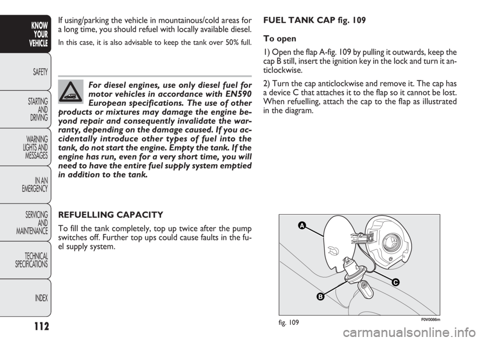
FUEL TANK CAP fig. 109
To open
1) Open the flap A-fig. 109 by pulling it outwards, keep the
cap B still, insert the ignition key in the lock and turn it an-
ticlockwise.
2) Turn the cap anticlockwise and remove it. The cap has
a device C that attaches it to the flap so it cannot be lost.
When refuelling, attach the cap to the flap as illustrated
in the diagram.