ESP FIAT DUCATO 2006 Owner handbook (in English)
[x] Cancel search | Manufacturer: FIAT, Model Year: 2006, Model line: DUCATO, Model: FIAT DUCATO 2006Pages: 238, PDF Size: 3.29 MB
Page 65 of 238
64
SAFETY
DEVICES
CORRECT USE
OF THE
VEHICLE
WARNING
LIGHTS AND
MESSAGES
IN AN
EMERGENCY
VEHICLE
MAINTENANCE
TECHNICAL
SPECIFICATIONS
INDEX
DASHBOARD
AND CONTROLS
TO INCREASE THE MEMORISED
SPEED
The speed memorised can be increased in
two ways:
❒pressing the accelerator and then
memorising the new speed reached;
or
❒moving the stalk upwards (+).
Each operation of the stalk will corre-
spond to a slight increase in speed (about
1 km/h), while keeping the stalk upwards
will correspond to a continuous speed in-
crease.
TO REDUCE MEMORISED
SPEED
The speed memorised can be increased in
two ways:
❒disengaging the device and then mem-
orising the new speed;
or
❒moving the stalk downwards (–) until
reaching the new speed which will be
memorised automatically.
Each operation of the stalk will corre-
spond to a slight reduction in speed (about
1 km/h), while keeping the stalk down-
wards will correspond to a continuous
speed reduction.DEVICE DISENGAGEMENT
The device can be disengaged in the fol-
lowing ways:
❒turning the knurled ring Ato OFF;
❒turning the engine off;
❒pressing the brake pedal or engaging
the hand brake;
❒pressing the clutch pedal;
❒shifting gear with automatic transmis-
sion in sequential mode;
❒with vehicle speed below the preset
limit;
❒pressing the accelerator pedal; in this
case the system is not really disen-
gaged but the request for acceleration
takes priority over the system. The
cruise control is however active and it
will not be necessary to press button
RES to resume previous conditions
after ending acceleration.The device is automatically deactivated in
one of the following cases:
❒ABS or ESP system cut-in;
❒system failure.
When travelling with the de-
vice on, never set the
gearshift lever to neutral.
In the event of device mal-
function or failure, turn the
knurled ring A to OFF and contact a
Fiat Dealership after checking the
protection fuse integrity.
WARNING
WARNING
Page 74 of 238
73
SAFETY
DEVICES
CORRECT USE
OF THE
VEHICLE
WARNING
LIGHTS AND
MESSAGES
IN AN
EMERGENCY
VEHICLE
MAINTENANCE
TECHNICAL
SPECIFICATIONS
INDEX
DASHBOARD
AND CONTROLS
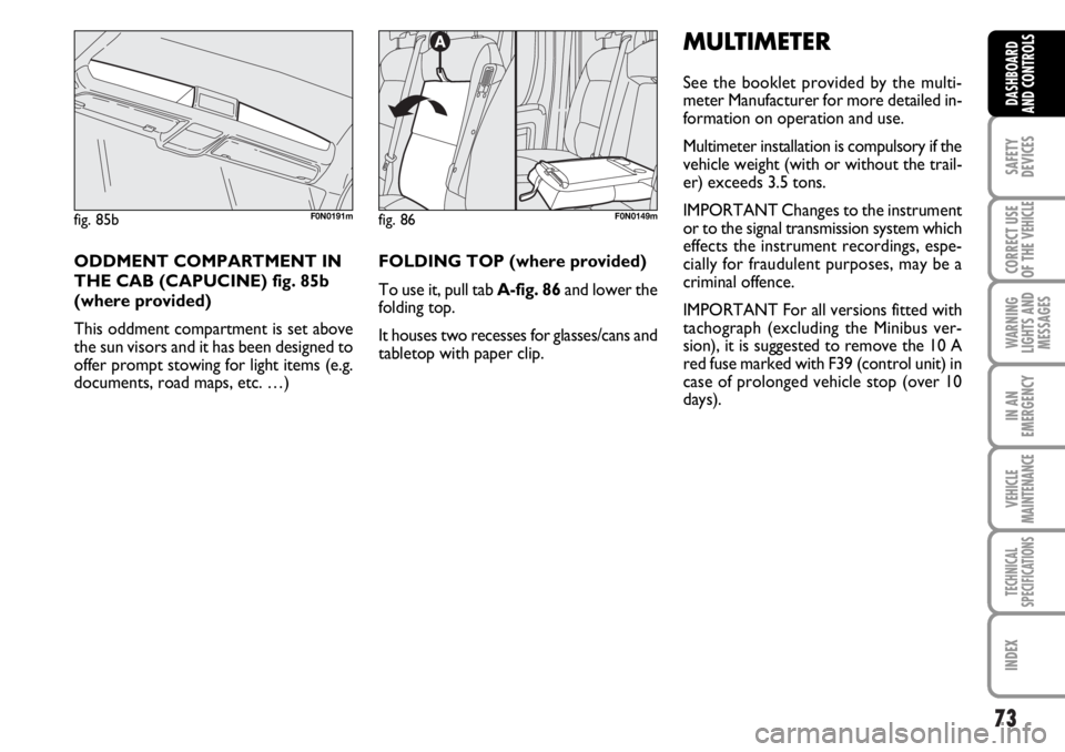
fig. 86F0N0149m
FOLDING TOP (where provided)
To use it, pull tab A-fig. 86and lower the
folding top.
It houses two recesses for glasses/cans and
tabletop with paper clip.
MULTIMETER
See the booklet provided by the multi-
meter Manufacturer for more detailed in-
formation on operation and use.
Multimeter installation is compulsory if the
vehicle weight (with or without the trail-
er) exceeds 3.5 tons.
IMPORTANT Changes to the instrument
or to the signal transmission system which
effects the instrument recordings, espe-
cially for fraudulent purposes, may be a
criminal offence.
IMPORTANT For all versions fitted with
tachograph (excluding the Minibus ver-
sion), it is suggested to remove the 10 A
red fuse marked with F39 (control unit) in
case of prolonged vehicle stop (over 10
days).
fig. 85bF0N0191m
ODDMENT COMPARTMENT IN
THE CAB (CAPUCINE) fig. 85b
(where provided)
This oddment compartment is set above
the sun visors and it has been designed to
offer prompt stowing for light items (e.g.
documents, road maps, etc. …)
Page 75 of 238
74
SAFETY
DEVICES
CORRECT USE
OF THE
VEHICLE
WARNING
LIGHTS AND
MESSAGES
IN AN
EMERGENCY
VEHICLE
MAINTENANCE
TECHNICAL
SPECIFICATIONS
INDEX
DASHBOARD
AND CONTROLS
IMPORTANT
Do not use abrasive detergents or sol-
vents to clean the device. To clean its ex-
ternal surface, use a wet cloth or special
products for cleaning synthetic materials.
The multimeter is installed and sealed with
lead by authorised personnel: access to
the device and relevant power and record-
ing cables is forbidden.
The vehicle owner is responsible for gov-
erning the instrument use. The inspection
must be carried out at least every two
years and will include a test to confirm
correct operation.
After the inspection, check that the plate
is updated with specified data.DOORS
CENTRAL DOOR
LOCKING/UNLOCKING SYSTEM
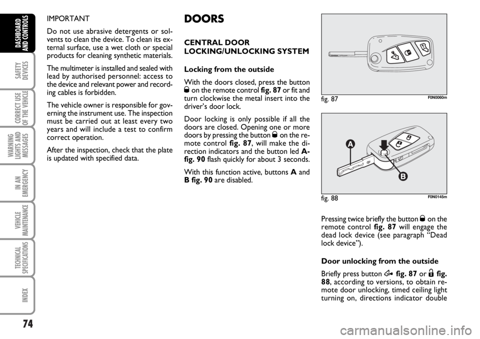
Locking from the outside
With the doors closed, press the button
Øon the remote control fig. 87or fit and
turn clockwise the metal insert into the
driver’s door lock.
Door locking is only possible if all the
doors are closed. Opening one or more
doors by pressing the button
Øon the re-
mote control fig. 87, will make the di-
rection indicators and the button led A-
fig. 90flash quickly for about 3 seconds.
With this function active, buttons Aand
B fig. 90are disabled.
fig. 87F0N0060m
Pressing twice briefly the button Øon the
remote control fig. 87will engage the
dead lock device (see paragraph “Dead
lock device”).
Door unlocking from the outside
Briefly press button
Æfig. 87or Ëfig.
88, according to versions, to obtain re-
mote door unlocking, timed ceiling light
turning on, directions indicator double
fig. 88F0N0145m
Page 78 of 238
77
SAFETY
DEVICES
CORRECT USE
OF THE
VEHICLE
WARNING
LIGHTS AND
MESSAGES
IN AN
EMERGENCY
VEHICLE
MAINTENANCE
TECHNICAL
SPECIFICATIONS
INDEX
DASHBOARD
AND CONTROLS
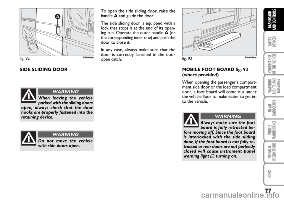
SIDE SLIDING DOORTo open the side sliding door, raise the
handle Aand guide the door.
The side sliding door is equipped with a
lock that stops it at the end of its open-
ing run. Operate the outer handle A(or
the corresponding inner one) and push the
door to close it.
In any case, always make sure that the
door is correctly fastened in the door
open catch.
MOBILE FOOT BOARD fig. 93
(where provided)
When opening the passenger’s compart-
ment side door or the load compartment
door, a foot board will come out under
the vehicle floor to make easier to get in-
to the vehicle.
fig. 92F0N0061m
When leaving the vehicle
parked with the sliding doors
open, always check that the door
hooks are properly fastened into the
retaining device.
WARNING
Do not move the vehicle
with side doors open.
WARNING
Always make sure the foot
board is fully retracted be-
fore moving off. Since the foot board
is interlocked with the side sliding
door, if the foot board is not fully re-
tracted or rear doors are not perfectly
closed will cause instrument panel
warning light
´turning on.
WARNING
fig. 93F0N0176m
Page 86 of 238
85
SAFETY
DEVICES
CORRECT USE
OF THE
VEHICLE
WARNING
LIGHTS AND
MESSAGES
IN AN
EMERGENCY
VEHICLE
MAINTENANCE
TECHNICAL
SPECIFICATIONS
INDEX
DASHBOARD
AND CONTROLS
BRAKE ASSIST
(emergency braking assistance
integral with ESP) (where provided)
The system, which cannot be cut out, rec-
ognizes emergency braking (on the ground
of the brake pedal operation speed) and
considerably increases the pressure in the
brake circuit.
Brake Assist is deactivated on the versions
equipped with ESP, in the event of ESP sys-
tem failure (indicated by warning light
áswitching on together with the message
on the multifunction display, where pro-
vided).
ESP SYSTEM
(Electronic Stability
Program)
(where provided)
The ESP system is an electronic system
controlling the vehicle stability in the event
of tyre grip loss.
The ESP system is therefore particularly
useful when grip conditions of the road sur-
faces changes.
In addition to the ESP system, ASR system
and Hill Holder, (where provided) also the
MSR system (adjusting the engine braking
torque) and the HBA system (improving
the braking force during emergency brak-
ing) are provided.
ESP SYSTEM INTERVENTION
It is signalled by the blinking of the warn-
ing light áon the instrument panel, to in-
form the driver that the vehicle is in crit-
ical stability and grip conditions.
When the ABS cuts in, and
you feel the brake pedal pul-
sating, do not remove your foot, but
keep it pressed; in doing so you will
stop in the shortest amount of space
possible under the current road con-
ditions.
WARNING
EBD failure
EBD failure is indicated by the turning on
of warning lights
>and xon the in-
strument panel together with the dedi-
cated message on the multifunction dis-
play (where provided), (see section
“Warning lights and messages”).
In this case with sharp braking the rear
wheels might lock too early, with the pos-
sibility of skidding. Drive extremely care-
fully to the nearest Fiat Dealership to have
the system checked.
If warning light xalone
comes on (together with the
message on the multifunction display,
where provided), stop the vehicle im-
mediately and contact the nearest Fi-
at Dealership. Fluid leaks from the hy-
draulic system, in fact, can compro-
mise the braking system, both tradi-
tional systems and systems with ABS.
WARNING
Page 87 of 238
86
SAFETY
DEVICES
CORRECT USE
OF THE
VEHICLE
WARNING
LIGHTS AND
MESSAGES
IN AN
EMERGENCY
VEHICLE
MAINTENANCE
TECHNICAL
SPECIFICATIONS
INDEX
DASHBOARD
AND CONTROLS
ESP SYSTEM ACTIVATION
The ESP system is automatically activat-
ed when the vehicle is started and cannot
be de-activated.
FAILURE INDICATIONS
In the event of failure, the ESP system is
automatically disconnected, the warning
light
á, comes on with fixed light on the
instrument panel, together with the mes-
sage on the multifunction display (where
provided) (see section “Warning lights and
messages”) and with the button led ASR.
In this case contact a Fiat Dealership as
soon as possible.
Performance of the ESP sys-
tem, in terms of active safe-
ty should not induce the driver to take
pointless and unnecessary risks. The
style of driving must in any case al-
ways be adapted to the conditions of
the road surface, visibility and traffic.
Road safety is always the driver’s re-
sponsibility.
WARNING
HILL HOLDER SYSTEM
This system is an integral part of the ESP
system and it is provided to facilitate start-
ing on slopes.
It will activate automatically with the fol-
lowing conditions:
❒uphill: vehicle at a standstill on a road
with a gradient higher than 5%, engine
running, clutch and brake pedal
pressed, gearbox to neutral or en-
gaged gear other than reverse.
❒downhill: vehicle at a standstill on a
road with a gradient higher than 5%,
engine running, clutch and brake ped-
al pressed and reverse gear engaged.
At pickup the ESP system control unit will
keep brake force on wheels until reaching
the torque suitable for starting, or in any
case for max. 2 seconds in order to pass
easily from the brake pedal to the accel-
erator pedal.
After two seconds without starting, the
system will deactivate automatically by re-
leasing gradually the brake force.
At releasing, the typical brake disengage-
ment noise indicating that the vehicle is
going to move will be heard.Failure indications
System failure is indicated by the turning
on of warning light
á(see section “Warn-
ing lights and messages”).
IMPORTANT The Hill Holder system is
not a parking brake therefore, never leave
the vehicle without having engaged the
handbrake, turned the engine off and en-
gaged the first speed.
For correct operation of the
ESP and ASR systems, the
tyres must absolutely be of the same
brand and type on all wheels, in per-
fect conditions and, above all, of
type, brand and size specified.
WARNING
Page 88 of 238
87
SAFETY
DEVICES
CORRECT USE
OF THE
VEHICLE
WARNING
LIGHTS AND
MESSAGES
IN AN
EMERGENCY
VEHICLE
MAINTENANCE
TECHNICAL
SPECIFICATIONS
INDEX
DASHBOARD
AND CONTROLS
MSR system
(engine braking torque control)
It is an integral part of the ASR system that
in case of sudden gear shifting, cuts in pro-
viding torque to the engine thus prevent-
ing excessive driving wheel drive that, spe-
cially in poor grip conditions, can lead to
loss of stability.
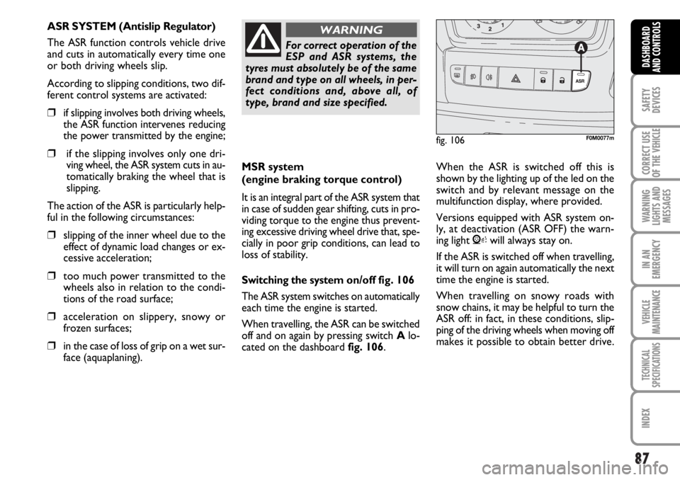
Switching the systemon/off fig. 106
The ASR system switches on automatically
each time the engine is started.
When travelling, the ASR can be switched
off and on again by pressing switch Alo-
cated on the dashboard fig. 106. When the ASR is switched off this is
shown by the lighting up of the led on the
switch and by relevant message on the
multifunction display, where provided.
Versions equipped with ASR system on-
ly, at deactivation (ASR OFF) the warn-
ing light Vwill always stay on.
If the ASR is switched off when travelling,
it will turn on again automatically the next
time the engine is started.
When travelling on snowy roads with
snow chains, it may be helpful to turn the
ASR off: in fact, in these conditions, slip-
ping of the driving wheels when moving off
makes it possible to obtain better drive.
For correct operation of the
ESP and ASR systems, the
tyres must absolutely be of the same
brand and type on all wheels, in per-
fect conditions and, above all, of
type, brand and size specified.
WARNING
fig. 106F0M0077m
ASR SYSTEM (Antislip Regulator)
The ASR function controls vehicle drive
and cuts in automatically every time one
or both driving wheels slip.
According to slipping conditions, two dif-
ferent control systems are activated:
❒if slipping involves both driving wheels,
the ASR function intervenes reducing
the power transmitted by the engine;
❒if the slipping involves only one dri-
ving wheel, the ASR system cuts in au-
tomatically braking the wheel that is
slipping.
The action of the ASR is particularly help-
ful in the following circumstances:
❒slipping of the inner wheel due to the
effect of dynamic load changes or ex-
cessive acceleration;
❒too much power transmitted to the
wheels also in relation to the condi-
tions of the road surface;
❒acceleration on slippery, snowy or
frozen surfaces;
❒in the case of loss of grip on a wet sur-
face (aquaplaning).
Page 91 of 238
90
SAFETY
DEVICES
CORRECT USE
OF THE
VEHICLE
WARNING
LIGHTS AND
MESSAGES
IN AN
EMERGENCY
VEHICLE
MAINTENANCE
TECHNICAL
SPECIFICATIONS
INDEX
DASHBOARD
AND CONTROLS
For proper operation, the
parking sensors shall always
be clean from mud, dirt, snow
or ice. When cleaning the sen-
sors, take the utmost care to prevent
their damaging; do not use therefore
dry or rough clothes. Sensors shall be
washed with clean water and vehicle
detergent, if required.
Parking manoeuvres howev-
er are always under the dri-
ver’s responsibility that shall always
check the absence of people (spe-
cially children) or animals in the ma-
noeuvre space. This system is just a
help for the driver but she/he shall
never reduce attention during dan-
gerous manoeuvres even if performed
at low speed.
WARNINGOPERATION WITH
TRAILER
Parking sensor operation is deactivated au-
tomatically when the trailer electric cable
plug is fitted into the vehicle tow hook
socket.
Sensors are reactivated when removing
the trailer cable plug.
In washing stations, clean sensors quickly
keeping the vapour jet/high pressure
washing nozzles at 10 cm at least from the
sensors.
Page 118 of 238
117
WARNING
LIGHTS AND
MESSAGES
IN AN
EMERGENCY
VEHICLE
MAINTENANCE
TECHNICAL
SPECIFICATIONS
INDEX
DASHBOARD
AND CONTROLS
SAFETY
DEVICES
CORRECT USE
OF THE VEHICLE
If the engine does not start at the first at-
tempt, return the ignition key to STOP
before repeating starting.
If, when the ignition key is at MAR, the in-
strument panel warning light
Yremains
lit together with warning light
mturn
the key to STOPand then back to MAR;
if the warning lights remain on, try with
the other keys provided with the vehicle.
IMPORTANT If the instrument panel
warning light
Ystays on glowing steadi-
ly, contact immediately Fiat Dealership.
IMPORTANT Never leave the ignition key
to MARwhen the engine is off.
The warning light
mwill
flash for 60 seconds at start-
up or during prolonged crank-
ing to indicate a fault in the
glow plug heating system. You can use
the vehicle as usual if the engine starts
but you should contact Fiat Dealership
as soon as possible.
HOW TO WARM UP THE
ENGINE AFTER IT HAS JUST
STARTED
Proceed as follows:
❒drive off slowly, letting the engine turn
at medium revs. Do not accelerate
abruptly;
❒do not drive at full performance for
the initial kilometres. Wait until the
coolant temperature gauge starts
moving.
Remember that the servo-
brake and power steering are
not operational until the en-
gine has been started, there-
fore much effort than usual is required
on the brake pedal and steering wheel.
Never bump start the engine
by pushing, towing or coast-
ing downhill as this could
cause fuel to flow into the
catalytic exhaust system and damage
it beyond repair.
STOPPING THE ENGINE
Turn the ignition to STOPwhile the en-
gine is idling.
IMPORTANT After a taxing drive, you
should allow the engine to “catch its
breath” before turning it off by letting it
idle to allow the temperature in the en-
gine compartment to fall.
A quick burst on the acceler-
ator before turning off the en-
gine serves absolutely no
practical purpose, it wastes
fuel and is damaging especially to tur-
bocharged engines.
Page 120 of 238
119
WARNING
LIGHTS AND
MESSAGES
IN AN
EMERGENCY
VEHICLE
MAINTENANCE
TECHNICAL
SPECIFICATIONS
INDEX
DASHBOARD
AND CONTROLS
SAFETY
DEVICES
CORRECT USE
OF THE VEHICLE
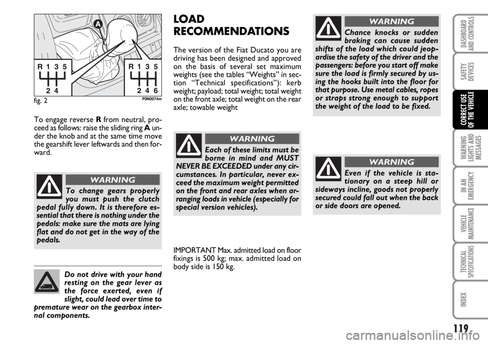
fig. 2F0N0074m
To change gears properly
you must push the clutch
pedal fully down. It is therefore es-
sential that there is nothing under the
pedals: make sure the mats are lying
flat and do not get in the way of the
pedals.
WARNING
Do not drive with your hand
resting on the gear lever as
the force exerted, even if
slight, could lead over time to
premature wear on the gearbox inter-
nal components.
To engage reverse R from neutral, pro-
ceed as follows: raise the sliding ring Aun-
der the knob and at the same time move
the gearshift lever leftwards and then for-
ward.
LOAD
RECOMMENDATIONS
The version of the Fiat Ducato you are
driving has been designed and approved
on the basis of several set maximum
weights (see the tables “Weights” in sec-
tion “Technical specifications”): kerb
weight; payload; total weight; total weight
on the front axle; total weight on the rear
axle; towable weight
Each of these limits must be
borne in mind and MUST
NEVER BE EXCEEDED under any cir-
cumstances. In particular, never ex-
ceed the maximum weight permitted
on the front and rear axles when ar-
ranging loads in vehicle (especially for
special version vehicles).Chance knocks or sudden
braking can cause sudden
shifts of the load which could jeop-
ardise the safety of the driver and the
passengers: before you start off make
sure the load is firmly secured by us-
ing the hooks built into the floor for
that purpose. Use metal cables, ropes
or straps strong enough to support
the weight of the load to be fixed.
WARNING
WARNING
Even if the vehicle is sta-
tionary on a steep hill or
sideways incline, goods not properly
secured could fall out when the back
or side doors are opened.
WARNING
IMPORTANT Max. admitted load on floor
fixings is 500 kg; max. admitted load on
body side is 150 kg.