ESP FIAT DUCATO 2006 Owner handbook (in English)
[x] Cancel search | Manufacturer: FIAT, Model Year: 2006, Model line: DUCATO, Model: FIAT DUCATO 2006Pages: 238, PDF Size: 3.29 MB
Page 121 of 238
120
WARNING
LIGHTS AND
MESSAGES
IN AN
EMERGENCY
VEHICLE
MAINTENANCE
TECHNICAL
SPECIFICATIONS
INDEX
DASHBOARD
AND CONTROLS
SAFETY
DEVICES
CORRECT USE
OF THE VEHICLE
CONTAINING
RUNNING COSTS
Here are some suggestions which may
help you to keep the running costs of your
vehicle down and lower the amount of
toxic emissions released into the atmos-
phere.
GENERAL CONSIDERATIONS
Vehicle maintenance
Carry out the checks and adjustments/reg-
ulations specified in the “Service Sched-
ule”.
Tyres
Check the pressure of the tyres routine-
ly at an interval of no more than 4 weeks:
if the pressure is too low, consumption
levels increase as resistance to rolling is
higher.
Unnecessary loads
Do not travel with too much luggage
stowed in the boot. The weight of the ve-
hicle (especially when driving in town) and
its trim greatly affects consumption and
stability.Roof rack/ski rack
Remove the roof rack or the ski rack from
the roof as soon as they are no longer
used. These accessories lower air pene-
tration and adversely affect consumption
levels. When needing to carry particular-
ly voluminous objects, preferably use a
trailer.
Electric devices
Use electric devices only for the amount
of time needed. Rear heated window, ad-
ditional headlights, windscreen wipers and
heater fan need a considerable amount of
energy, therefore increasing the require-
ment of current increases fuel consump-
tion (up to +25% in the urban cycle).
Climate control
The air conditioner is an additional load
which greatly affects the engine leading to
higher consumption (on average up to
+20%). When the temperature outside
the vehicle permits it, use the air vents
where possible.
Spoilers
The use of non-certified aerodynamic
items may adversely affect air drag and
consumption levels.
Observe the enforced rules if
you need to carry a spare
can of petrol. Only use a homologat-
ed can and secure it to the load an-
choring eyebolts. Even given these
precautions, the risk of fire in the
event of an accident is increased.
WARNING
In addition to these general precautions,
some simple measures could enhance dri-
ving safety, comfort and the length of the
vehicle’s life:
❒distribute the load evenly over the
load floor: if you need to concentrate
it all in one point choose the part be-
tween the axles;
❒remember that the lower the load is,
the lower the vehicle’s centre of grav-
ity will be, contributing to a safe drive;
you should therefore always position
the heavier goods at the bottom;
❒finally, remember that the way in
which the vehicle moves is influenced
by the weight being carried. In partic-
ular, stopping distance lengthens par-
ticularly at high speed.
Page 128 of 238
127
IN AN
EMERGENCY
VEHICLE
MAINTENANCE
TECHNICAL
SPECIFICATIONS
INDEX
DASHBOARD
AND CONTROLS
SAFETY
DEVICES
CORRECT USE
OF THE
VEHICLE
WARNING
LIGHTS AND
MESSAGES
GENERAL WARNINGS ...................................................... 128
LOW BRAKE FLUID.............................................................. 128
HANDBRAKE ON ................................................................. 128
AIR BAG FAILURE ................................................................. 129
ENGINE COOLANT
HIGH TEMPERATURE .......................................................... 129
LOW BATTERY CHARGE .................................................. 130
LOW ENGINE OIL PRESSURE........................................... 130
EXHAUSTED OIL ................................................................. 130
INCOMPLETE DOOR LOCKING..................................... 131
SEAT BELTS NOT FASTENED ........................................... 131
EBD SYSTEM FAILURE ......................................................... 131
INJECTION SYSTEM FAILURE .......................................... 132
FRONT PASSENGER AIR BAG DEACTIVATED .......... 132
ABS SYSTEM FAILURE .......................................................... 132
FUEL RESERVE......................................................................... 132
GLOW PLUG WARMING ................................................. 133
GLOW PLUG WARMING FAILURE ................................ 133
WATER IN DIESEL FUEL FILTER ..................................... 133
VEHICLE PROTECTION SYSTEM FAILURE
FIAT CODE ............................................................................. 133
EXTERNAL LIGHTS FAILURE ............................................ 134
REAR FOGLIGHTS ................................................................ 134
GENERIC FAILURE INDICATION .................................. 134
ESP - ASR SYSTEM FAILURE .............................................. 135
DIESEL PARTICULATE FILTER CLOGGED ................... 135BRAKE PAD WEAR .............................................................. 135
HILL HOLDER FAILURE ..................................................... 135
PARKING SENSOR FAILURE ............................................. 136
SIDELIGHTS AND LOW BEAMS ...................................... 136
FOLLOW ME HOME ............................................................ 136
FRONT FOG LIGHTS ........................................................... 136
LEFT-HAND DIRECTION INDICATOR ........................ 136
RIGHT-HAND DIRECTION INDICATOR .................... 137
CRUISE CONTROL ............................................................. 137
MAIN BEAM HEADLIGHTS ................................................ 137
ASR SYSTEM ........................................................................... 137
POWER STEERING FAILURE ............................................. 137
POSSIBLE PRESENCE OF ICE ON THE ROAD ............ 138
LIMITED RANGE ................................................................... 138
SPEED LIMIT EXCEEDED ................................................... 138
ENGINE COOLANT LEVEL................................................. 138
SCHEDULED SERVICING ................................................... 138
SELF-LEVELLING SUSPENSIONS FAILURE .................... 138
AUTOMATIC TRANSMISSION FAILURE/
MAX. GEARBOX OIL TEMPERATURE ........................... 138
W W
A A
R R
N N
I I
N N
G G
L L
I I
G G
H H
T T
S S
A A
N N
D D
M M
E E
S S
S S
A A
G G
E E
S S
Page 136 of 238

135
IN AN
EMERGENCY
VEHICLE
MAINTENANCE
TECHNICAL
SPECIFICATIONS
INDEX
DASHBOARD
AND CONTROLS
SAFETY
DEVICES
CORRECT USE
OF THE
VEHICLE
WARNING
LIGHTS AND
MESSAGES
DIESEL PARTICULATE
FILTER CLOGGED
The warning light turns on when
the diesel particulate filter is clogged and
the driving conditions do not enable to ac-
tivate automatically the reclaiming proce-
dure.
To enable the cleaning procedure, keep
the vehicle running until the warning light
turns off.
The display will show the dedicated mes-
sage.ESP - ASR SYSTEM
FAILURE
(amber) (where provided)
HILL HOLDER FAILURE
(amber) (where provided)
Turning the ignition key to MARthe
warning light turns on, but it should go off
after few seconds.
ESP-ASR system failure
If the warning light does not go off or stays
on when travelling together with the but-
ton led ASR, contact Fiat Dealership.
On certain versions the dedicated mes-
sage is displayed.
NoteWarning light flashing when driving
indicates that the ESP system is active.
Hill Holder failure
The warning light will turn on when the
Hill Holder system is faulty. Contact Fiat
Dealership as soon as possible.
On certain versions the dedicated mes-
sage is displayed.
áh
BRAKE PAD WEAR
(amber)
The warning light on the dial
turns on if the front brake pads are worn;
in this case have them changed as soon
as possible.
On certain versions the dedicated mes-
sage is displayed.
d
Page 142 of 238
141
WARNING
LIGHTS AND
MESSAGES
VEHICLE
MAINTENANCE
TECHNICAL
SPECIFICATIONS
INDEX
DASHBOARD
AND CONTROLS
SAFETY
DEVICES
CORRECT USE
OF THE
VEHICLE
IN AN
EMERGENCY
IMPORTANT Do not directly connect the
negative terminals of the two batteries:
sparks could ignite the flammable gas from
the battery. If the other battery is fitted in
another vehicle, prevent accidental con-
tacts between the metal parts of the two
vehicles.BUMP STARTING
Never bump start the engine (by pushing,
towing, or coasting downhill) as this could
cause fuel to flow into the catalytic ex-
haust system and damage it beyond repair.
IMPORTANT Remember that the brake
booster and the power steering system
are not operating until the engine is start-
ed, a greater effort will therefore be re-
quired to press the brake pedal or turn
the steering wheel.IF A TYRE
IS PUNCTURED
GENERAL INSTRUCTIONS
Wheel changing and correct use of the
jack and spare wheel call for some pre-
cautions as listed below.
Alert other drivers that the
vehicle is stationary in com-
pliance with the regulations in force:
hazard warning lights, warning trian-
gle etc. Any passengers on board
should leave the vehicle, especially if
it is heavily laden. Passengers should
stay away from oncoming traffic
while the wheel is being changed on.
Pull the handbrake.
WARNING
Page 145 of 238
144
WARNING
LIGHTS AND
MESSAGES
VEHICLE
MAINTENANCE
TECHNICAL
SPECIFICATIONS
IINDEX
DASHBOARD
AND CONTROLS
SAFETY
DEVICES
CORRECT USE
OF THE
VEHICLE
IN AN
EMERGENCY
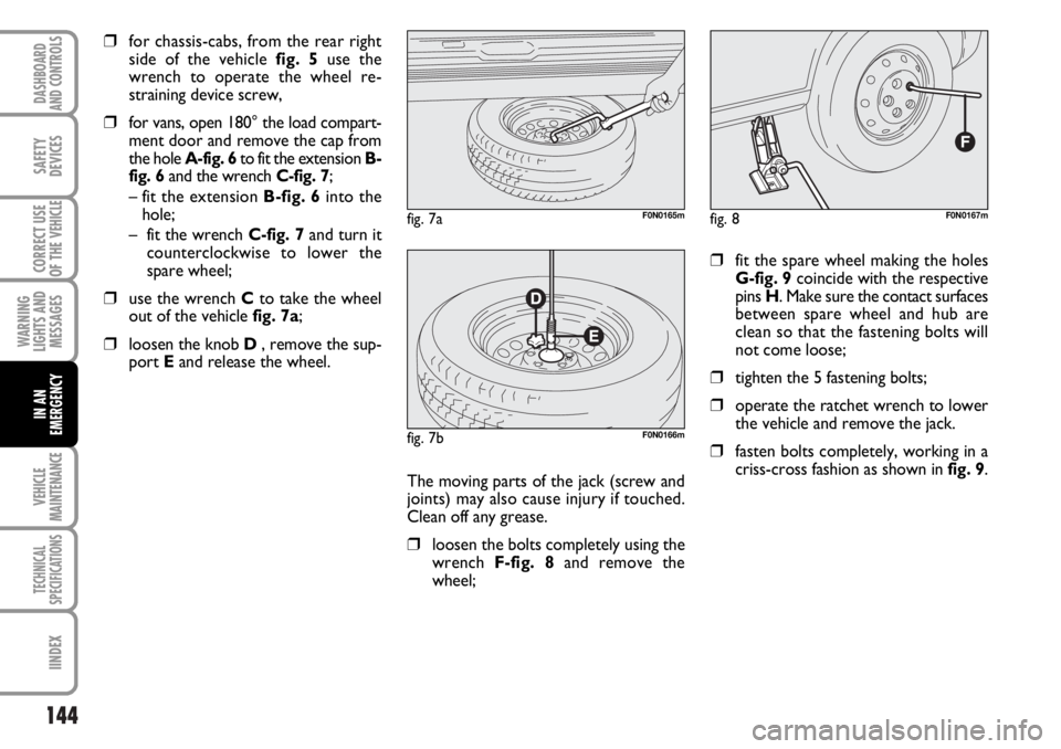
❒for chassis-cabs, from the rear right
side of the vehicle fig. 5use the
wrench to operate the wheel re-
straining device screw,
❒for vans, open 180° the load compart-
ment door and remove the cap from
the hole A-fig. 6to fit the extension B-
fig. 6and the wrench C-fig. 7;
– fit the extension B-fig. 6into the
hole;
– fit the wrench C-fig. 7and turn it
counterclockwise to lower the
spare wheel;
❒use the wrench Cto take the wheel
out of the vehicle fig. 7a;
❒loosen the knob D , remove the sup-
port Eand release the wheel.
❒fit the spare wheel making the holes
G-fig. 9coincide with the respective
pins H. Make sure the contact surfaces
between spare wheel and hub are
clean so that the fastening bolts will
not come loose;
❒tighten the 5 fastening bolts;
❒operate the ratchet wrench to lower
the vehicle and remove the jack.
❒fasten bolts completely, working in a
criss-cross fashion as shown in fig. 9.
fig. 8F0N0167m
The moving parts of the jack (screw and
joints) may also cause injury if touched.
Clean off any grease.
❒loosen the bolts completely using the
wrench F-fig. 8and remove the
wheel;
fig. 7aF0N0165m
fig. 7bF0N0166m
Page 149 of 238
148
WARNING
LIGHTS AND
MESSAGES
VEHICLE
MAINTENANCE
TECHNICAL
SPECIFICATIONS
IINDEX
DASHBOARD
AND CONTROLS
SAFETY
DEVICES
CORRECT USE
OF THE
VEHICLE
IN AN
EMERGENCY
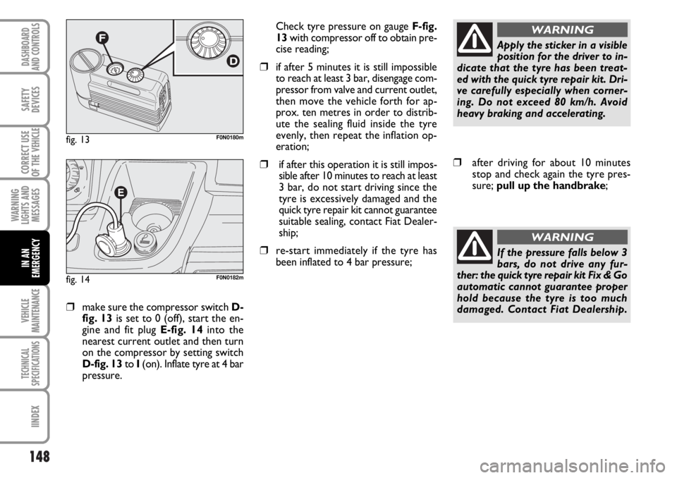
❒make sure the compressor switch D-
fig. 13is set to 0 (off), start the en-
gine and fit plug E-fig. 14into the
nearest current outlet and then turn
on the compressor by setting switch
D-fig. 13to I(on). Inflate tyre at 4 bar
pressure. Check tyre pressure on gauge F-fig.
13with compressor off to obtain pre-
cise reading;
❒if after 5 minutes it is still impossible
to reach at least 3 bar, disengage com-
pressor from valve and current outlet,
then move the vehicle forth for ap-
prox. ten metres in order to distrib-
ute the sealing fluid inside the tyre
evenly, then repeat the inflation op-
eration;
❒if after this operation it is still impos-
sible after 10 minutes to reach at least
3 bar, do not start driving since the
tyre is excessively damaged and the
quick tyre repair kit cannot guarantee
suitable sealing, contact Fiat Dealer-
ship;
❒re-start immediately if the tyre has
been inflated to 4 bar pressure;
fig. 13F0N0180m
fig. 14F0N0182m
Apply the sticker in a visible
position for the driver to in-
dicate that the tyre has been treat-
ed with the quick tyre repair kit. Dri-
ve carefully especially when corner-
ing. Do not exceed 80 km/h. Avoid
heavy braking and accelerating.
WARNING
❒after driving for about 10 minutes
stop and check again the tyre pres-
sure; pull up the handbrake;
If the pressure falls below 3
bars, do not drive any fur-
ther: the quick tyre repair kit Fix & Go
automatic cannot guarantee proper
hold because the tyre is too much
damaged. Contact Fiat Dealership.
WARNING
Page 151 of 238
150
WARNING
LIGHTS AND
MESSAGES
VEHICLE
MAINTENANCE
TECHNICAL
SPECIFICATIONS
IINDEX
DASHBOARD
AND CONTROLS
SAFETY
DEVICES
CORRECT USE
OF THE
VEHICLE
IN AN
EMERGENCY
WHEN NEEDING TO
CHANGE A BULB
GENERAL INSTRUCTIONS
❒When a light is not working, check
that the corresponding fuse is intact
before changing a bulb. For the loca-
tion of fuses, refer to the paragraph “If
a fuse blows” in this section;
❒Before changing a bulb check the con-
tacts for oxidation;
❒Burnt bulbs must be replaced by oth-
ers of the same type and power;
❒Always check the height of the head-
light beam after changing a bulb.
IMPORTANT The headlight inner surface
may be lightly misted over: this is not a
fault but a natural fact due to low tem-
perature and the level of air humidity. It
will disappear as soon the headlights are
turned on. The presence of drops inside
the headlights means water infiltration,
therefore contact Fiat Dealership.
TYPES OF BULBS
Various types of bulbs are fitted to your
vehicle:
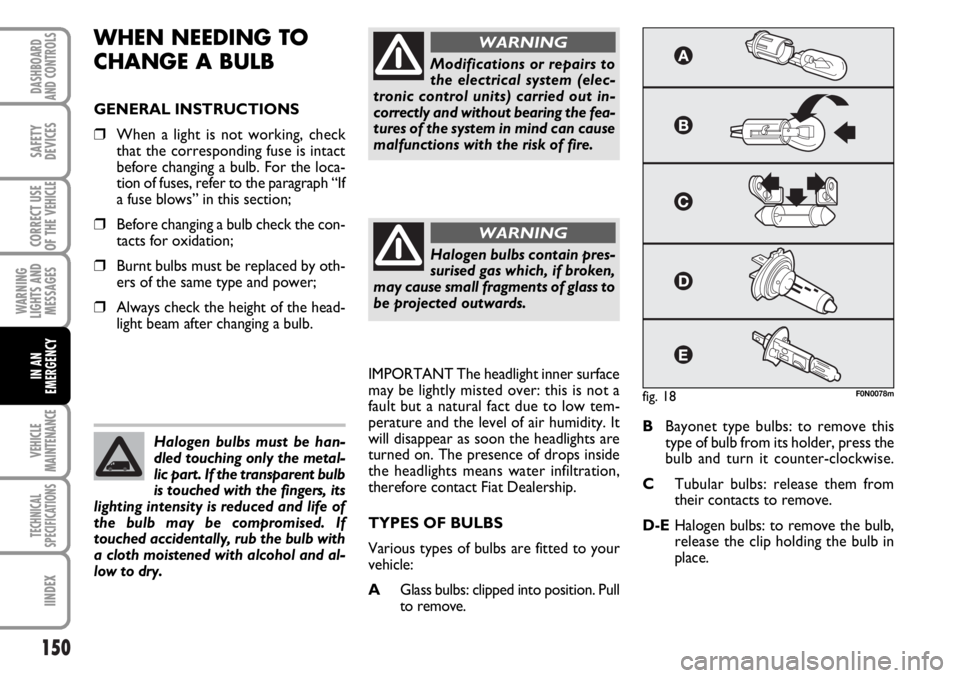
AGlass bulbs: clipped into position. Pull
to remove.BBayonet type bulbs: to remove this
type of bulb from its holder, press the
bulb and turn it counter-clockwise.
CTubular bulbs: release them from
their contacts to remove.
D-EHalogen bulbs: to remove the bulb,
release the clip holding the bulb in
place. Halogen bulbs must be han-
dled touching only the metal-
lic part. If the transparent bulb
is touched with the fingers, its
lighting intensity is reduced and life of
the bulb may be compromised. If
touched accidentally, rub the bulb with
a cloth moistened with alcohol and al-
low to dry.
Modifications or repairs to
the electrical system (elec-
tronic control units) carried out in-
correctly and without bearing the fea-
tures of the system in mind can cause
malfunctions with the risk of fire.
WARNING
Halogen bulbs contain pres-
surised gas which, if broken,
may cause small fragments of glass to
be projected outwards.
WARNING
fig. 18F0N0078m
Page 160 of 238
159
WARNING
LIGHTS AND
MESSAGES
VEHICLE
MAINTENANCE
TECHNICAL
SPECIFICATIONS
INDEX
DASHBOARD
AND CONTROLS
SAFETY
DEVICES
CORRECT USE
OF THE
VEHICLE
IN AN
EMERGENCY
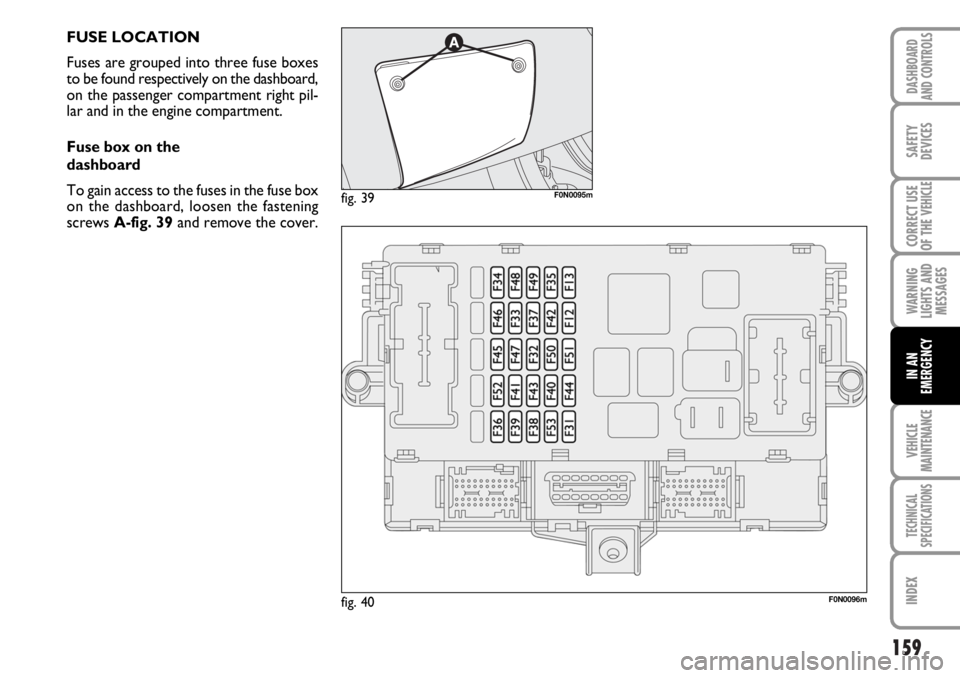
FUSE LOCATION
Fuses are grouped into three fuse boxes
to be found respectively on the dashboard,
on the passenger compartment right pil-
lar and in the engine compartment.
Fuse box on the
dashboard
To gain access to the fuses in the fuse box
on the dashboard, loosen the fastening
screws A-fig. 39and remove the cover.
fig. 40F0N0096m
fig. 39F0N0095m
Page 163 of 238
162
WARNING
LIGHTS AND
MESSAGES
VEHICLE
MAINTENANCE
TECHNICAL
SPECIFICATIONS
IINDEX
DASHBOARD
AND CONTROLS
SAFETY
DEVICES
CORRECT USE
OF THE
VEHICLE
IN AN
EMERGENCY
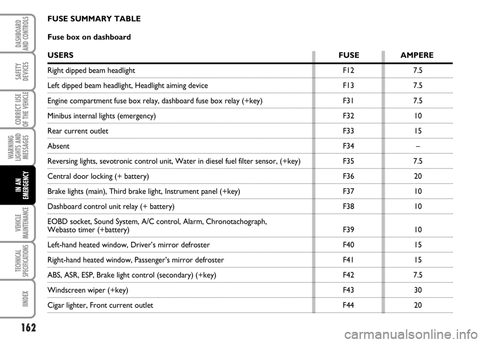
FUSE SUMMARY TABLE
Fuse box on dashboard
USERSFUSE AMPERE
Right dipped beam headlight F12 7.5
Left dipped beam headlight, Headlight aiming device F13 7.5
Engine compartment fuse box relay, dashboard fuse box relay (+key) F31 7.5
Minibus internal lights (emergency) F32 10
Rear current outlet F33 15
AbsentF34 –
Reversing lights, sevotronic control unit, Water in diesel fuel filter sensor, (+key) F35 7.5
Central door locking (+ battery) F36 20
Brake lights (main), Third brake light, Instrument panel (+key) F37 10
Dashboard control unit relay (+ battery) F38 10
EOBD socket, Sound System, A/C control, Alarm, Chronotachograph,
Webasto timer (+battery) F39 10
Left-hand heated window, Driver’s mirror defroster F40 15
Right-hand heated window, Passenger’s mirror defroster F41 15
ABS, ASR, ESP, Brake light control (secondary) (+key) F42 7.5
Windscreen wiper (+key) F43 30
Cigar lighter, Front current outlet F44 20
Page 181 of 238
180
WARNING
LIGHTS AND
MESSAGES
TECHNICAL
SPECIFICATIONS
INDEX
DASHBOARD
AND CONTROLS
SAFETY
DEVICES
CORRECT USE
OF THE VEHICLE
IN AN
EMERGENCY
VEICHLE
MAINTENANCE
ENGINE OIL CONSUMPTION
Max engine oil consumption is usually 400
grams every 1,000 km.
When the vehicle is new, the engine needs
to run in, therefore the engine oil con-
sumption can only be considered stabilised
after the first 5,000 - 6,000 km.
IMPORTANT The oil consumption de-
pends on driving style and the conditions
under which the vehicle is used.
IMPORTANT After adding or changing
the oil, let the engine turn over for a few
seconds and wait a few minutes after turn-
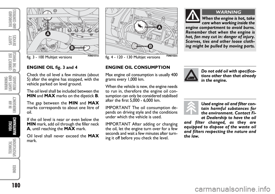
ing it off before you check the level. ENGINE OIL fig. 3 and 4
Check the oil level a few minutes (about
5) after the engine has stopped, with the
vehicle parked on level ground.
The oil level shall be included between the
MINand MAXmarks on the dipstick B.
The gap between the MINand MAX
marks corresponds to about one litre of
oil.
If the oil level is near or even below the
MINmark, add oil through the filler neck
A, until reaching the MAXmark.
Oil level shall never exceed the MAX
mark.
fig. 3 - 100 Multijet versionsF0N0101mfig. 4 - 120 - 130 Multijet versionsF0N0102m
When the engine is hot, take
care when working inside the
engine compartment to avoid burns.
Remember that when the engine is
hot, fan may cut in: danger of injury.
Scarves, ties and other loose cloth-
ing might be pulled by moving parts.
WARNING
Do not add oil with specifica-
tions other than that already
in the engine.
Used engine oil and filter con-
tain harmful substances for
the environment. Contact Fi-
at Dealership to have the oil
and filter changed, as they are
equipped to dispose of the waste oil
and filters respecting the nature and
the law.