brake light FIAT DUCATO 2006 Owner handbook (in English)
[x] Cancel search | Manufacturer: FIAT, Model Year: 2006, Model line: DUCATO, Model: FIAT DUCATO 2006Pages: 238, PDF Size: 3.29 MB
Page 136 of 238
135
IN AN
EMERGENCY
VEHICLE
MAINTENANCE
TECHNICAL
SPECIFICATIONS
INDEX
DASHBOARD
AND CONTROLS
SAFETY
DEVICES
CORRECT USE
OF THE
VEHICLE
WARNING
LIGHTS AND
MESSAGES
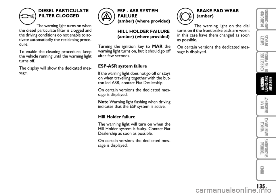
DIESEL PARTICULATE
FILTER CLOGGED
The warning light turns on when
the diesel particulate filter is clogged and
the driving conditions do not enable to ac-
tivate automatically the reclaiming proce-
dure.
To enable the cleaning procedure, keep
the vehicle running until the warning light
turns off.
The display will show the dedicated mes-
sage.ESP - ASR SYSTEM
FAILURE
(amber) (where provided)
HILL HOLDER FAILURE
(amber) (where provided)
Turning the ignition key to MARthe
warning light turns on, but it should go off
after few seconds.
ESP-ASR system failure
If the warning light does not go off or stays
on when travelling together with the but-
ton led ASR, contact Fiat Dealership.
On certain versions the dedicated mes-
sage is displayed.
NoteWarning light flashing when driving
indicates that the ESP system is active.
Hill Holder failure
The warning light will turn on when the
Hill Holder system is faulty. Contact Fiat
Dealership as soon as possible.
On certain versions the dedicated mes-
sage is displayed.
áh
BRAKE PAD WEAR
(amber)
The warning light on the dial
turns on if the front brake pads are worn;
in this case have them changed as soon
as possible.
On certain versions the dedicated mes-
sage is displayed.
d
Page 142 of 238
141
WARNING
LIGHTS AND
MESSAGES
VEHICLE
MAINTENANCE
TECHNICAL
SPECIFICATIONS
INDEX
DASHBOARD
AND CONTROLS
SAFETY
DEVICES
CORRECT USE
OF THE
VEHICLE
IN AN
EMERGENCY
IMPORTANT Do not directly connect the
negative terminals of the two batteries:
sparks could ignite the flammable gas from
the battery. If the other battery is fitted in
another vehicle, prevent accidental con-
tacts between the metal parts of the two
vehicles.BUMP STARTING
Never bump start the engine (by pushing,
towing, or coasting downhill) as this could
cause fuel to flow into the catalytic ex-
haust system and damage it beyond repair.
IMPORTANT Remember that the brake
booster and the power steering system
are not operating until the engine is start-
ed, a greater effort will therefore be re-
quired to press the brake pedal or turn
the steering wheel.IF A TYRE
IS PUNCTURED
GENERAL INSTRUCTIONS
Wheel changing and correct use of the
jack and spare wheel call for some pre-
cautions as listed below.
Alert other drivers that the
vehicle is stationary in com-
pliance with the regulations in force:
hazard warning lights, warning trian-
gle etc. Any passengers on board
should leave the vehicle, especially if
it is heavily laden. Passengers should
stay away from oncoming traffic
while the wheel is being changed on.
Pull the handbrake.
WARNING
Page 144 of 238
143
WARNING
LIGHTS AND
MESSAGES
VEHICLE
MAINTENANCE
TECHNICAL
SPECIFICATIONS
INDEX
DASHBOARD
AND CONTROLS
SAFETY
DEVICES
CORRECT USE
OF THE
VEHICLE
IN AN
EMERGENCY
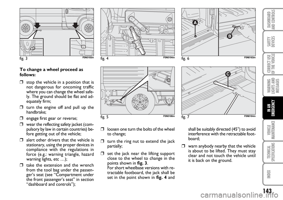
To change a wheel proceed as
follows:
❒stop the vehicle in a position that is
not dangerous for oncoming traffic
where you can change the wheel safe-
ly. The ground should be flat and ad-
equately firm;
❒turn the engine off and pull up the
handbrake;
❒engage first gear or reverse;
❒wear the reflecting safety jacket (com-
pulsory by law in certain countries) be-
fore getting out of the vehicle;
❒alert other drivers that the vehicle is
stationary, using the proper devices in
compliance with the regulations in
force (e.g.: warning triangle, hazard
warning lights, etc …);
❒take the extension and the wrench
from the tool bag under the passen-
ger’s seat (see “Compartment under
the front passenger’s seat” in section
“dashboard and controls”);
❒loosen one turn the bolts of the wheel
to change;
❒turn the ring nut to extend the jack
partially;
❒set the jack near the lifting support
close to the wheel to change in the
points shown in fig. 3.
For short wheelbase versions with re-
tractable footboard, the jack shall be
set in the point shown in fig. 4andshall be suitably directed (45°) to avoid
interference with the retractable foot-
board;
❒warn anybody nearby that the vehicle
is about to be lifted. They must stay
clear and not touch the vehicle until
it is back on the ground.
fig. 3F0N0193mfig. 4F0N0194m
fig. 5F0N0186m
fig. 6F0N0163m
fig. 7F0N0164m
Page 148 of 238

147
WARNING
LIGHTS AND
MESSAGES
VEHICLE
MAINTENANCE
TECHNICAL
SPECIFICATIONS
INDEX
DASHBOARD
AND CONTROLS
SAFETY
DEVICES
CORRECT USE
OF THE
VEHICLE
IN AN
EMERGENCY
The cylinder contains ethyl-
ene glycol. The cylinder con-
tains latex: it can cause allergic reac-
tions. It is harmful if ingested or in-
haled and irritant for the eyes and in
case of contact. In case of contact
rinse immediately with water and take
off contaminated clothes. If swal-
lowed, do not induce vomit, rinse out
the mouth, drink a lot of water and
call the doctor immediately. Keep
away from children. This product must
not be used by asthmatics. Do not in-
hale vapours. Call the doctor imme-
diately in case of allergic reactions.
Keep the cylinder in the space provid-
ed for the purpose and far from heat.
The sealing fluid has limited life.
WARNINGReplace the cylinder if sealer
has run out. Do not throw
away the cylinder and the
sealing fluid. Have the sealing
fluid and the cylinder disposed of in
compliance with national and local
regulations.
Put on the protection gloves
provided together with quick
tyre repair kit.
WARNING
❒Pull up the handbrake. Loosen tyre
inflation valve cap, take out the filler
hose A-fig. 12and screw the ring nut
Bon the tyre valve;
fig. 12F0N0179m
INFLATING PROCEDURE
Page 149 of 238
148
WARNING
LIGHTS AND
MESSAGES
VEHICLE
MAINTENANCE
TECHNICAL
SPECIFICATIONS
IINDEX
DASHBOARD
AND CONTROLS
SAFETY
DEVICES
CORRECT USE
OF THE
VEHICLE
IN AN
EMERGENCY
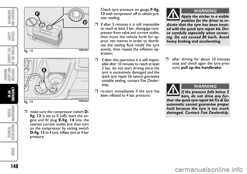
❒make sure the compressor switch D-
fig. 13is set to 0 (off), start the en-
gine and fit plug E-fig. 14into the
nearest current outlet and then turn
on the compressor by setting switch
D-fig. 13to I(on). Inflate tyre at 4 bar
pressure. Check tyre pressure on gauge F-fig.
13with compressor off to obtain pre-
cise reading;
❒if after 5 minutes it is still impossible
to reach at least 3 bar, disengage com-
pressor from valve and current outlet,
then move the vehicle forth for ap-
prox. ten metres in order to distrib-
ute the sealing fluid inside the tyre
evenly, then repeat the inflation op-
eration;
❒if after this operation it is still impos-
sible after 10 minutes to reach at least
3 bar, do not start driving since the
tyre is excessively damaged and the
quick tyre repair kit cannot guarantee
suitable sealing, contact Fiat Dealer-
ship;
❒re-start immediately if the tyre has
been inflated to 4 bar pressure;
fig. 13F0N0180m
fig. 14F0N0182m
Apply the sticker in a visible
position for the driver to in-
dicate that the tyre has been treat-
ed with the quick tyre repair kit. Dri-
ve carefully especially when corner-
ing. Do not exceed 80 km/h. Avoid
heavy braking and accelerating.
WARNING
❒after driving for about 10 minutes
stop and check again the tyre pres-
sure; pull up the handbrake;
If the pressure falls below 3
bars, do not drive any fur-
ther: the quick tyre repair kit Fix & Go
automatic cannot guarantee proper
hold because the tyre is too much
damaged. Contact Fiat Dealership.
WARNING
Page 150 of 238
149
WARNING
LIGHTS AND
MESSAGES
VEHICLE
MAINTENANCE
TECHNICAL
SPECIFICATIONS
INDEX
DASHBOARD
AND CONTROLS
SAFETY
DEVICES
CORRECT USE
OF THE
VEHICLE
IN AN
EMERGENCY
❒if at laest 3 bar pressure is read, re-
store proper pressure specified in
paragraph” Tyre pressure” in section
“Technical Specifications” (with engine
running and handbrake on) and
restart;
❒drive with the utmost care to the
nearest Fiat Dealership.
FOR CHECKING AND
RESTORING PRESSURE ONLY
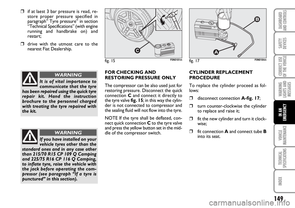
The compressor can be also used just for
restoring pressure. Disconnect the quick
connection Cand connect it directly to
the tyre valve fig. 15; in this way the cylin-
der is not connected to compressor and
the sealing fluid will not flow into the tyre.
NOTE If the tyre shall be deflated, con-
nect quick connection Cto the tyre valve
and press the yellow button set in the mid-
dle of the compressor switch.CYLINDER REPLACEMENT
PROCEDURE
To replace the cylinder proceed as fol-
lows:
❒disconnect connection A-fig. 17;
❒turn counter-clockwise the cylinder
to replace and raise it;
❒fit the new cylinder and turn it clock-
wise;
❒fit connection Aand connect tube B
into its seat.
It is of vital importance to
communicate that the tyre
has been repaired using the quick tyre
repair kit. Hand the instruction
brochure to the personnel charged
with treating the tyre repaired with
the kit.
WARNING
fig. 17F0N0184mfig. 15F0N0181m
If you have installed on your
vehicle tyres other than the
standard ones and in any case other
than 215/70 R15 CP 109 Q Camping
and 225/75 R16 CP 116 Q Camping,
to inflate tyre, raise the vehicle with
the jack before operating the com-
pressor (see paragraph “If a tyre is
punctured” in this section).
WARNING
Page 152 of 238
151
WARNING
LIGHTS AND
MESSAGES
VEHICLE
MAINTENANCE
TECHNICAL
SPECIFICATIONS
INDEX
DASHBOARD
AND CONTROLS
SAFETY
DEVICES
CORRECT USE
OF THE
VEHICLE
IN AN
EMERGENCY
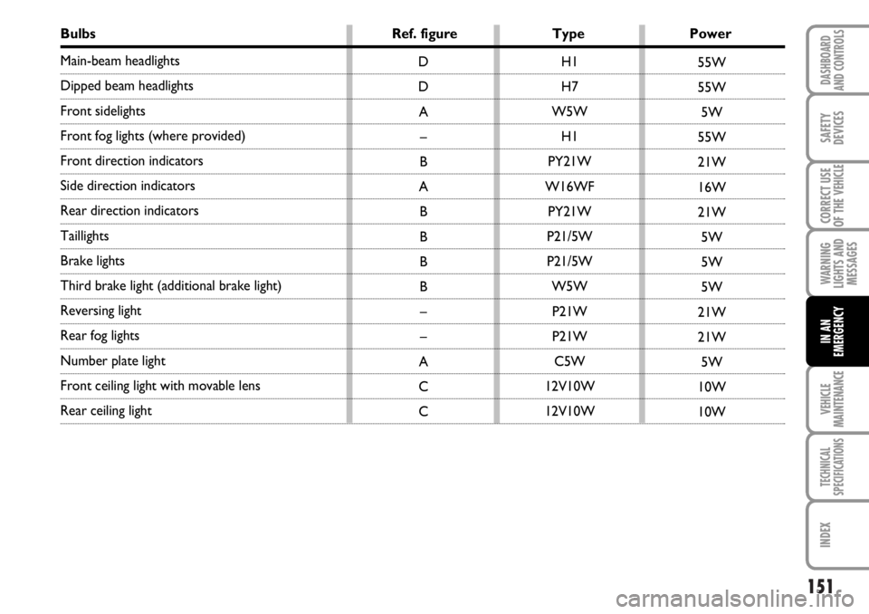
Bulbs Ref. figure Type Power
Main-beam headlights
Dipped beam headlights
Front sidelights
Front fog lights (where provided)
Front direction indicators
Side direction indicators
Rear direction indicators
Taillights
Brake lights
Third brake light (additional brake light)
Reversing light
Rear fog lights
Number plate light
Front ceiling light with movable lens
Rear ceiling lightH1
H7
W5W
H1
PY21W
W16WF
PY21W
P21/5W
P21/5W
W5W
P21W
P21W
C5W
12V10W
12V10W D
D
A
–
B
A
B
B
B
B
–
–
A
C
C55W
55W
5W
55W
21W
16W
21W
5W
5W
5W
21W
21W
5W
10W
10W
Page 156 of 238
155
WARNING
LIGHTS AND
MESSAGES
VEHICLE
MAINTENANCE
TECHNICAL
SPECIFICATIONS
INDEX
DASHBOARD
AND CONTROLS
SAFETY
DEVICES
CORRECT USE
OF THE
VEHICLE
IN AN
EMERGENCY
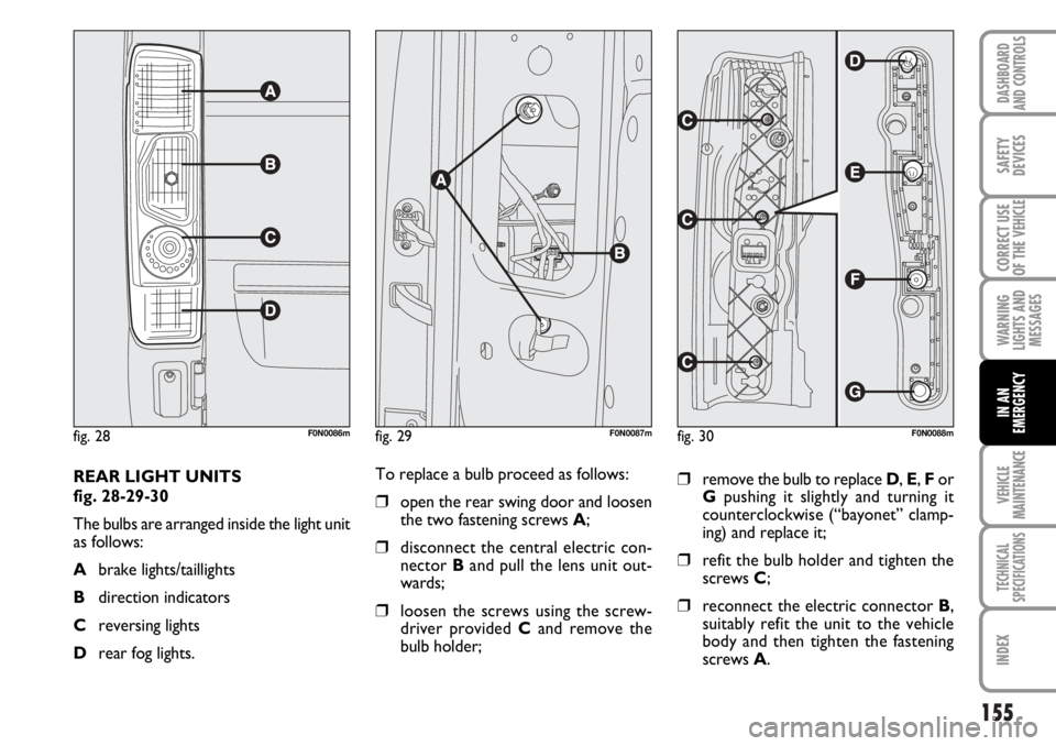
REAR LIGHT UNITS
fig. 28-29-30
The bulbs are arranged inside the light unit
as follows:
Abrake lights/taillights
Bdirection indicators
Creversing lights
Drear fog lights.
fig. 28F0N0086m
To replace a bulb proceed as follows:
❒open the rear swing door and loosen
the two fastening screws A;
❒disconnect the central electric con-
nector B and pull the lens unit out-
wards;
❒loosen the screws using the screw-
driver provided Cand remove the
bulb holder;
❒remove the bulb to replace D, E, For
Gpushing it slightly and turning it
counterclockwise (“bayonet” clamp-
ing) and replace it;
❒refit the bulb holder and tighten the
screws C;
❒reconnect the electric connector B,
suitably refit the unit to the vehicle
body and then tighten the fastening
screws A.
fig. 30F0N0088mfig. 29F0N0087m
Page 157 of 238
156
WARNING
LIGHTS AND
MESSAGES
VEHICLE
MAINTENANCE
TECHNICAL
SPECIFICATIONS
IINDEX
DASHBOARD
AND CONTROLS
SAFETY
DEVICES
CORRECT USE
OF THE
VEHICLE
IN AN
EMERGENCY
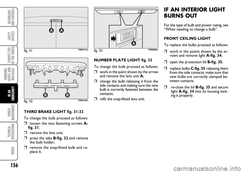
THIRD BRAKE LIGHT fig. 31-32
To change the bulb proceed as follows:
❒loosen the two fastening screws A-
fig. 31;
❒remove the lens unit;
❒press the tabs B-fig. 32and remove
the bulb holder;
❒remove the snap-fitted bulb and re-
place it.NUMBER PLATE LIGHT fig. 33
To change the bulb proceed as follows:
❒work in the point shown by the arrow
and remove the lens unit A;
❒change the bulb releasing it from the
side contacts and making sure the new
bulb is correctly fastened between the
contacts;
❒refit the snap-fitted lens unit.
IF AN INTERIOR LIGHT
BURNS OUT
For the type of bulb and power rating, see
“When needing to change a bulb”.
FRONT CEILING LIGHT
To replace the bulbs proceed as follows:
❒work in the points shown by the ar-
rows and remove light A-fig. 34;
❒open the protection lid B-fig. 35;
❒replace bulbs C-fig. 35releasing them
from the side contacts; make sure that
new bulbs are correctly clamped be-
tween contacts;
❒re-close the lid B-fig. 35and secure
light A-fig. 34into its housing lock-
ing it properly.
fig. 32F0N0142m
fig. 33F0N0089mfig. 31F0N0141m
Page 163 of 238
162
WARNING
LIGHTS AND
MESSAGES
VEHICLE
MAINTENANCE
TECHNICAL
SPECIFICATIONS
IINDEX
DASHBOARD
AND CONTROLS
SAFETY
DEVICES
CORRECT USE
OF THE
VEHICLE
IN AN
EMERGENCY
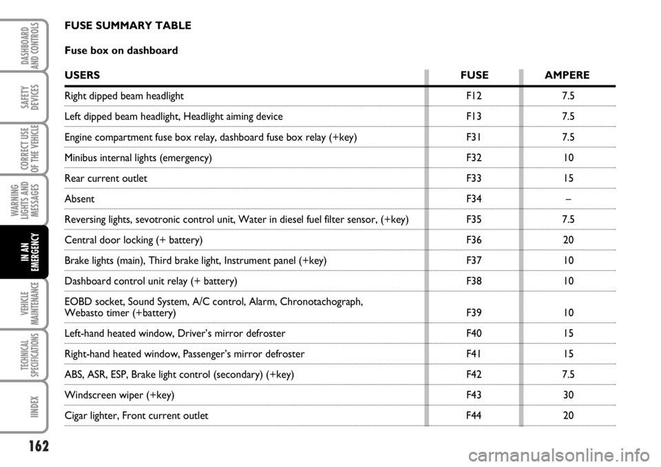
FUSE SUMMARY TABLE
Fuse box on dashboard
USERSFUSE AMPERE
Right dipped beam headlight F12 7.5
Left dipped beam headlight, Headlight aiming device F13 7.5
Engine compartment fuse box relay, dashboard fuse box relay (+key) F31 7.5
Minibus internal lights (emergency) F32 10
Rear current outlet F33 15
AbsentF34 –
Reversing lights, sevotronic control unit, Water in diesel fuel filter sensor, (+key) F35 7.5
Central door locking (+ battery) F36 20
Brake lights (main), Third brake light, Instrument panel (+key) F37 10
Dashboard control unit relay (+ battery) F38 10
EOBD socket, Sound System, A/C control, Alarm, Chronotachograph,
Webasto timer (+battery) F39 10
Left-hand heated window, Driver’s mirror defroster F40 15
Right-hand heated window, Passenger’s mirror defroster F41 15
ABS, ASR, ESP, Brake light control (secondary) (+key) F42 7.5
Windscreen wiper (+key) F43 30
Cigar lighter, Front current outlet F44 20