engine FIAT DUCATO 2006 Owner handbook (in English)
[x] Cancel search | Manufacturer: FIAT, Model Year: 2006, Model line: DUCATO, Model: FIAT DUCATO 2006Pages: 238, PDF Size: 3.29 MB
Page 63 of 238
62
SAFETY
DEVICES
CORRECT USE
OF THE
VEHICLE
WARNING
LIGHTS AND
MESSAGES
IN AN
EMERGENCY
VEHICLE
MAINTENANCE
TECHNICAL
SPECIFICATIONS
INDEX
DASHBOARD
AND CONTROLS
RAIN SENSOR
(where provided)
The rain sensor is located behind the dri-
ving mirror in contact with the windscreen
and has the purpose of automatically ad-
just, during the intermittent operation, the
frequency of the windscreen wiper
strokes as to the rain intensity.
IMPORTANT Keep clean the glass in the
sensor area.
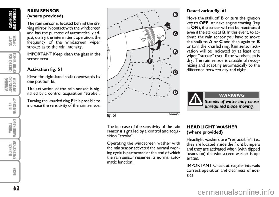
Activation fig. 61
Move the right-hand stalk downwards by
one position B.
The activation of the rain sensor is sig-
nalled by a control acquisition “stroke”.
Turning the knurled ring Fit is possible to
increase the sensitivity of the rain sensor.
The increase of the sensitivity of the rain
sensor is signalled by a control and acqui-
sition “stroke”.
Operating the windscreen washer with
the rain sensor activated the normal wash-
ing cycle is performed at the end of which
the rain sensor resumes its normal auto-
matic function.HEADLIGHT WASHER
(where provided)
Headlight washers are “retractable”, i.e.:
they are located inside the front bumpers
and they are activated when (with dipped
beams on) the windscreen washer is op-
erated.
IMPORTANT Check at regular intervals
correct operation and cleanness of noz-
zles. Deactivation fig. 61
Move the stalk off Bor turn the ignition
key to OFF. At next engine starting (key
at ON), the sensor will not be reactivated
even if the stalk is at B. In this event, to ac-
tivate the rain sensor you have to move
the stalk to Aor Cand then again to B
or turn the knurled ring. Rain sensor acti-
vation will be indicated by at least one
wiper “stroke” even if the windscreen is
dry. The rain sensor is capable of recog-
nizing and adapting automatically to the
difference between day and night.
fig. 61F0N0038m
Streaks of water may cause
unrequired blade moving.
WARNING
Page 65 of 238
64
SAFETY
DEVICES
CORRECT USE
OF THE
VEHICLE
WARNING
LIGHTS AND
MESSAGES
IN AN
EMERGENCY
VEHICLE
MAINTENANCE
TECHNICAL
SPECIFICATIONS
INDEX
DASHBOARD
AND CONTROLS
TO INCREASE THE MEMORISED
SPEED
The speed memorised can be increased in
two ways:
❒pressing the accelerator and then
memorising the new speed reached;
or
❒moving the stalk upwards (+).
Each operation of the stalk will corre-
spond to a slight increase in speed (about
1 km/h), while keeping the stalk upwards
will correspond to a continuous speed in-
crease.
TO REDUCE MEMORISED
SPEED
The speed memorised can be increased in
two ways:
❒disengaging the device and then mem-
orising the new speed;
or
❒moving the stalk downwards (–) until
reaching the new speed which will be
memorised automatically.
Each operation of the stalk will corre-
spond to a slight reduction in speed (about
1 km/h), while keeping the stalk down-
wards will correspond to a continuous
speed reduction.DEVICE DISENGAGEMENT
The device can be disengaged in the fol-
lowing ways:
❒turning the knurled ring Ato OFF;
❒turning the engine off;
❒pressing the brake pedal or engaging
the hand brake;
❒pressing the clutch pedal;
❒shifting gear with automatic transmis-
sion in sequential mode;
❒with vehicle speed below the preset
limit;
❒pressing the accelerator pedal; in this
case the system is not really disen-
gaged but the request for acceleration
takes priority over the system. The
cruise control is however active and it
will not be necessary to press button
RES to resume previous conditions
after ending acceleration.The device is automatically deactivated in
one of the following cases:
❒ABS or ESP system cut-in;
❒system failure.
When travelling with the de-
vice on, never set the
gearshift lever to neutral.
In the event of device mal-
function or failure, turn the
knurled ring A to OFF and contact a
Fiat Dealership after checking the
protection fuse integrity.
WARNING
WARNING
Page 66 of 238
65
SAFETY
DEVICES
CORRECT USE
OF THE
VEHICLE
WARNING
LIGHTS AND
MESSAGES
IN AN
EMERGENCY
VEHICLE
MAINTENANCE
TECHNICAL
SPECIFICATIONS
INDEX
DASHBOARD
AND CONTROLS
CEILING LIGHTS
FRONT CEILING LIGHT WITH
SPOT LIGHTS
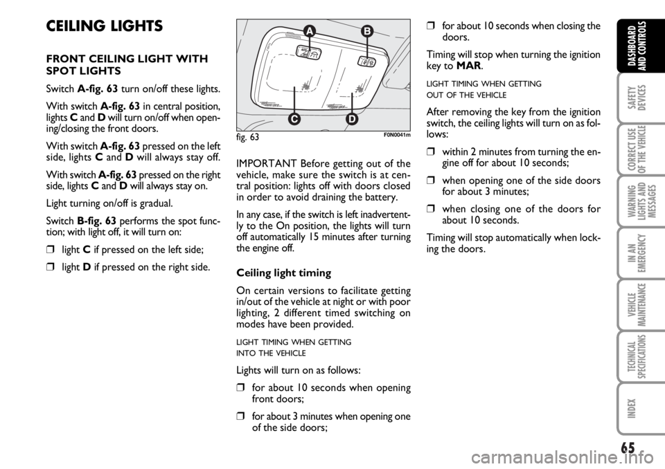
Switch A-fig. 63turn on/off these lights.
With switch A-fig. 63in central position,
lights Cand Dwill turn on/off when open-
ing/closing the front doors.
With switch A-fig. 63pressed on the left
side, lights Cand Dwill always stay off.
With switch A-fig. 63pressed on the right
side, lights Cand Dwill always stay on.
Light turning on/off is gradual.
Switch B-fig. 63performs the spot func-
tion; with light off, it will turn on:
❒light Cif pressed on the left side;
❒light Dif pressed on the right side.IMPORTANT Before getting out of the
vehicle, make sure the switch is at cen-
tral position: lights off with doors closed
in order to avoid draining the battery.
In any case, if the switch is left inadvertent-
ly to the On position, the lights will turn
off automatically 15 minutes after turning
the engine off.
Ceiling light timing
On certain versions to facilitate getting
in/out of the vehicle at night or with poor
lighting, 2 different timed switching on
modes have been provided.
LIGHT TIMING WHEN GETTING
INTO THE VEHICLE
Lights will turn on as follows:
❒for about 10 seconds when opening
front doors;
❒for about 3 minutes when opening one
of the side doors;
❒for about 10 seconds when closing the
doors.
Timing will stop when turning the ignition
key to MAR.
LIGHT TIMING WHEN GETTING
OUT OF THE VEHICLE
After removing the key from the ignition
switch, the ceiling lights will turn on as fol-
lows:
❒within 2 minutes from turning the en-
gine off for about 10 seconds;
❒when opening one of the side doors
for about 3 minutes;
❒when closing one of the doors for
about 10 seconds.
Timing will stop automatically when lock-
ing the doors.
fig. 63F0N0041m
Page 82 of 238
81
SAFETY
DEVICES
CORRECT USE
OF THE
VEHICLE
WARNING
LIGHTS AND
MESSAGES
IN AN
EMERGENCY
VEHICLE
MAINTENANCE
TECHNICAL
SPECIFICATIONS
INDEX
DASHBOARD
AND CONTROLS
fig. 100F0N0063m
fig. 101F0N0064m
fig. 102F0N0065m
IMPORTANT Before opening the bonnet,
check that windscreen wiper arms are not
lifted from the windscreen.
TO CLOSE THE BONNET
Proceed as follows:
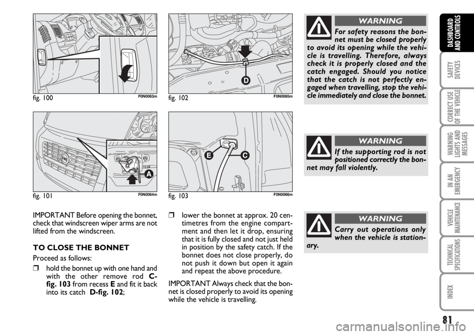
❒hold the bonnet up with one hand and
with the other remove rod C-
fig. 103 from recess Eand fit it back
into its catch D-fig. 102;
❒lower the bonnet at approx. 20 cen-
timetres from the engine compart-
ment and then let it drop, ensuring
that it is fully closed and not just held
in position by the safety catch. If the
bonnet does not close properly, do
not push it down but open it again
and repeat the above procedure.
IMPORTANT Always check that the bon-
net is closed properly to avoid its opening
while the vehicle is travelling.
fig. 103F0N0066m
For safety reasons the bon-
net must be closed properly
to avoid its opening while the vehi-
cle is travelling. Therefore, always
check it is properly closed and the
catch engaged. Should you notice
that the catch is not perfectly en-
gaged when travelling, stop the vehi-
cle immediately and close the bonnet.
WARNING
If the supporting rod is not
positioned correctly the bon-
net may fall violently.
WARNING
Carry out operations only
when the vehicle is station-
ary.
WARNING
Page 86 of 238
85
SAFETY
DEVICES
CORRECT USE
OF THE
VEHICLE
WARNING
LIGHTS AND
MESSAGES
IN AN
EMERGENCY
VEHICLE
MAINTENANCE
TECHNICAL
SPECIFICATIONS
INDEX
DASHBOARD
AND CONTROLS
BRAKE ASSIST
(emergency braking assistance
integral with ESP) (where provided)
The system, which cannot be cut out, rec-
ognizes emergency braking (on the ground
of the brake pedal operation speed) and
considerably increases the pressure in the
brake circuit.
Brake Assist is deactivated on the versions
equipped with ESP, in the event of ESP sys-
tem failure (indicated by warning light
áswitching on together with the message
on the multifunction display, where pro-
vided).
ESP SYSTEM
(Electronic Stability
Program)
(where provided)
The ESP system is an electronic system
controlling the vehicle stability in the event
of tyre grip loss.
The ESP system is therefore particularly
useful when grip conditions of the road sur-
faces changes.
In addition to the ESP system, ASR system
and Hill Holder, (where provided) also the
MSR system (adjusting the engine braking
torque) and the HBA system (improving
the braking force during emergency brak-
ing) are provided.
ESP SYSTEM INTERVENTION
It is signalled by the blinking of the warn-
ing light áon the instrument panel, to in-
form the driver that the vehicle is in crit-
ical stability and grip conditions.
When the ABS cuts in, and
you feel the brake pedal pul-
sating, do not remove your foot, but
keep it pressed; in doing so you will
stop in the shortest amount of space
possible under the current road con-
ditions.
WARNING
EBD failure
EBD failure is indicated by the turning on
of warning lights
>and xon the in-
strument panel together with the dedi-
cated message on the multifunction dis-
play (where provided), (see section
“Warning lights and messages”).
In this case with sharp braking the rear
wheels might lock too early, with the pos-
sibility of skidding. Drive extremely care-
fully to the nearest Fiat Dealership to have
the system checked.
If warning light xalone
comes on (together with the
message on the multifunction display,
where provided), stop the vehicle im-
mediately and contact the nearest Fi-
at Dealership. Fluid leaks from the hy-
draulic system, in fact, can compro-
mise the braking system, both tradi-
tional systems and systems with ABS.
WARNING
Page 87 of 238
86
SAFETY
DEVICES
CORRECT USE
OF THE
VEHICLE
WARNING
LIGHTS AND
MESSAGES
IN AN
EMERGENCY
VEHICLE
MAINTENANCE
TECHNICAL
SPECIFICATIONS
INDEX
DASHBOARD
AND CONTROLS
ESP SYSTEM ACTIVATION
The ESP system is automatically activat-
ed when the vehicle is started and cannot
be de-activated.
FAILURE INDICATIONS
In the event of failure, the ESP system is
automatically disconnected, the warning
light
á, comes on with fixed light on the
instrument panel, together with the mes-
sage on the multifunction display (where
provided) (see section “Warning lights and
messages”) and with the button led ASR.
In this case contact a Fiat Dealership as
soon as possible.
Performance of the ESP sys-
tem, in terms of active safe-
ty should not induce the driver to take
pointless and unnecessary risks. The
style of driving must in any case al-
ways be adapted to the conditions of
the road surface, visibility and traffic.
Road safety is always the driver’s re-
sponsibility.
WARNING
HILL HOLDER SYSTEM
This system is an integral part of the ESP
system and it is provided to facilitate start-
ing on slopes.
It will activate automatically with the fol-
lowing conditions:
❒uphill: vehicle at a standstill on a road
with a gradient higher than 5%, engine
running, clutch and brake pedal
pressed, gearbox to neutral or en-
gaged gear other than reverse.
❒downhill: vehicle at a standstill on a
road with a gradient higher than 5%,
engine running, clutch and brake ped-
al pressed and reverse gear engaged.
At pickup the ESP system control unit will
keep brake force on wheels until reaching
the torque suitable for starting, or in any
case for max. 2 seconds in order to pass
easily from the brake pedal to the accel-
erator pedal.
After two seconds without starting, the
system will deactivate automatically by re-
leasing gradually the brake force.
At releasing, the typical brake disengage-
ment noise indicating that the vehicle is
going to move will be heard.Failure indications
System failure is indicated by the turning
on of warning light
á(see section “Warn-
ing lights and messages”).
IMPORTANT The Hill Holder system is
not a parking brake therefore, never leave
the vehicle without having engaged the
handbrake, turned the engine off and en-
gaged the first speed.
For correct operation of the
ESP and ASR systems, the
tyres must absolutely be of the same
brand and type on all wheels, in per-
fect conditions and, above all, of
type, brand and size specified.
WARNING
Page 88 of 238
87
SAFETY
DEVICES
CORRECT USE
OF THE
VEHICLE
WARNING
LIGHTS AND
MESSAGES
IN AN
EMERGENCY
VEHICLE
MAINTENANCE
TECHNICAL
SPECIFICATIONS
INDEX
DASHBOARD
AND CONTROLS
MSR system
(engine braking torque control)
It is an integral part of the ASR system that
in case of sudden gear shifting, cuts in pro-
viding torque to the engine thus prevent-
ing excessive driving wheel drive that, spe-
cially in poor grip conditions, can lead to
loss of stability.
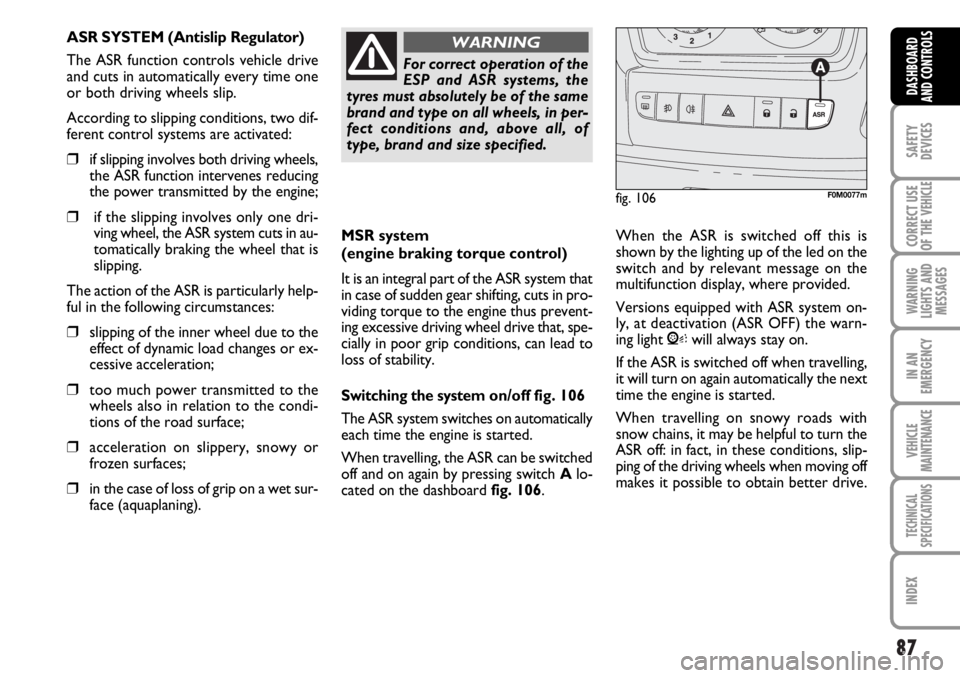
Switching the systemon/off fig. 106
The ASR system switches on automatically
each time the engine is started.
When travelling, the ASR can be switched
off and on again by pressing switch Alo-
cated on the dashboard fig. 106. When the ASR is switched off this is
shown by the lighting up of the led on the
switch and by relevant message on the
multifunction display, where provided.
Versions equipped with ASR system on-
ly, at deactivation (ASR OFF) the warn-
ing light Vwill always stay on.
If the ASR is switched off when travelling,
it will turn on again automatically the next
time the engine is started.
When travelling on snowy roads with
snow chains, it may be helpful to turn the
ASR off: in fact, in these conditions, slip-
ping of the driving wheels when moving off
makes it possible to obtain better drive.
For correct operation of the
ESP and ASR systems, the
tyres must absolutely be of the same
brand and type on all wheels, in per-
fect conditions and, above all, of
type, brand and size specified.
WARNING
fig. 106F0M0077m
ASR SYSTEM (Antislip Regulator)
The ASR function controls vehicle drive
and cuts in automatically every time one
or both driving wheels slip.
According to slipping conditions, two dif-
ferent control systems are activated:
❒if slipping involves both driving wheels,
the ASR function intervenes reducing
the power transmitted by the engine;
❒if the slipping involves only one dri-
ving wheel, the ASR system cuts in au-
tomatically braking the wheel that is
slipping.
The action of the ASR is particularly help-
ful in the following circumstances:
❒slipping of the inner wheel due to the
effect of dynamic load changes or ex-
cessive acceleration;
❒too much power transmitted to the
wheels also in relation to the condi-
tions of the road surface;
❒acceleration on slippery, snowy or
frozen surfaces;
❒in the case of loss of grip on a wet sur-
face (aquaplaning).
Page 89 of 238
88
SAFETY
DEVICES
CORRECT USE
OF THE
VEHICLE
WARNING
LIGHTS AND
MESSAGES
IN AN
EMERGENCY
VEHICLE
MAINTENANCE
TECHNICAL
SPECIFICATIONS
INDEX
DASHBOARD
AND CONTROLS
The performance of the sys-
tem, in terms of active safe-
ty should not induce the driver to take
pointless and unnecessary risks. The
style of driving must in any case al-
ways be adapted to the conditions of
the road surface, visibility an traffic.
Road safety is always the driver’s re-
sponsibility.
WARNING
For correct operation of the ASR system,
the tyres must absolutely be of the same
brand and type on all wheels, in perfect
conditions and, above all, of type, brand
and size specified.
FAILURE INDICATIONS
In the event of failure, the ASR system is
automatically disconnected, the warning
light
á, comes on with fixed light on the
instrument panel, together with the mes-
sage on the multifunction display (where
provided) (see section “Warning lights and
messages”) and with the button led ASR.
In this case contact a Fiat Dealership as
soon as possible.
EOBD SYSTEM
The EOBD system (European On Board
Diagnosis) allows continuous diagnosis of
the components of the vehicle correlat-
ed with emissions.
It also alerts the driver, by turning on the
warning light
Uon the instrument panel
(together with relevant message on the
multifunction display, where provided)
(see section “Warning lights and mes-
sages”), when these conditions are no
longer in peak conditions.
The objective is:
❒to keep the system efficiency under
control;
❒warn when a fault causes emissions
levels to increase;
❒warn of the need to replace deterio-
rated components.
The system also has a diagnostic connec-
tor that can be interfaced with appropri-
ate tools, which makes it possible to read
the error codes stored in the control unit,
together with a series of specific parame-
ters for engine operation and diagnosis.
This check can also be carried out by the
traffic police.IMPORTANT After eliminating the in-
convenience, to check the system com-
pletely, Fiat Dealerships are obliged to run
a bench test and, if necessary, road tests
which may also call for a long journey.
If turning the ignition key to
MAR, the warning light
Udoes
not turn on or if, while travel-
ling it turns on glowing steadily
or flashing (together with the message on
the multifunction display, where provid-
ed), contact Fiat Dealership as soon as
possible. Warning light
Uoperation can
be checked by means of special equipment
by traffic agents. Always comply with the
traffic regulations in force in the country
where you are travelling.
Page 96 of 238
95
SAFETY
DEVICES
CORRECT USE
OF THE
VEHICLE
WARNING
LIGHTS AND
MESSAGES
IN AN
EMERGENCY
VEHICLE
MAINTENANCE
TECHNICAL
SPECIFICATIONS
INDEX
DASHBOARD
AND CONTROLS
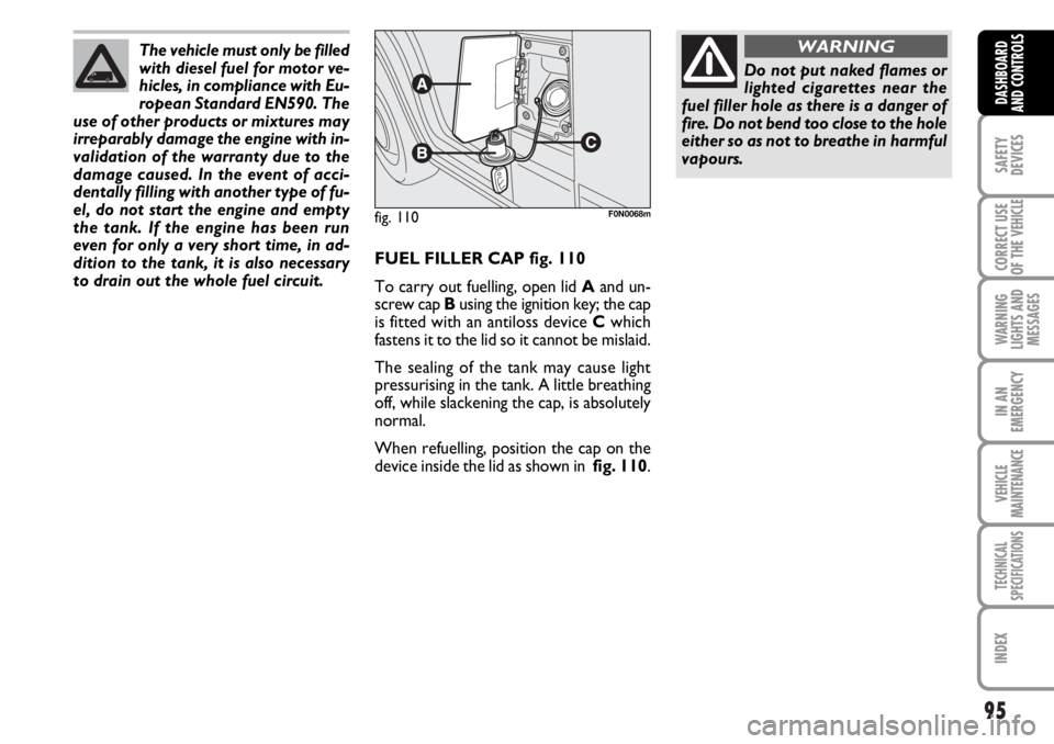
FUEL FILLER CAP fig. 110
To carry out fuelling, open lid Aand un-
screw cap Busing the ignition key; the cap
is fitted with an antiloss device Cwhich
fastens it to the lid so it cannot be mislaid.
The sealing of the tank may cause light
pressurising in the tank. A little breathing
off, while slackening the cap, is absolutely
normal.
When refuelling, position the cap on the
device inside the lid as shown in fig. 110.
fig. 110F0N0068m
Do not put naked flames or
lighted cigarettes near the
fuel filler hole as there is a danger of
fire. Do not bend too close to the hole
either so as not to breathe in harmful
vapours.
WARNINGThe vehicle must only be filled
with diesel fuel for motor ve-
hicles, in compliance with Eu-
ropean Standard EN590. The
use of other products or mixtures may
irreparably damage the engine with in-
validation of the warranty due to the
damage caused. In the event of acci-
dentally filling with another type of fu-
el, do not start the engine and empty
the tank. If the engine has been run
even for only a very short time, in ad-
dition to the tank, it is also necessary
to drain out the whole fuel circuit.
Page 100 of 238
99
CORRECT USE
OF THE
VEHICLE
WARNING
LIGHTS AND
MESSAGES
IN AN
EMERGENCY
VEHICLE
MAINTENANCE
TECHNICAL
SPECIFICATIONS
INDEX
DASHBOARD
AND CONTROLS
SAFETY
DEVICES
After you have made the ad-
justment, always make sure
that the loop is attached firmly in one
of the preset positions. To do this,
with the button released, exert a fur-
ther pressure to allow the anchoring
device to catch if release did not take
place at one of the preset positions.
WARNING
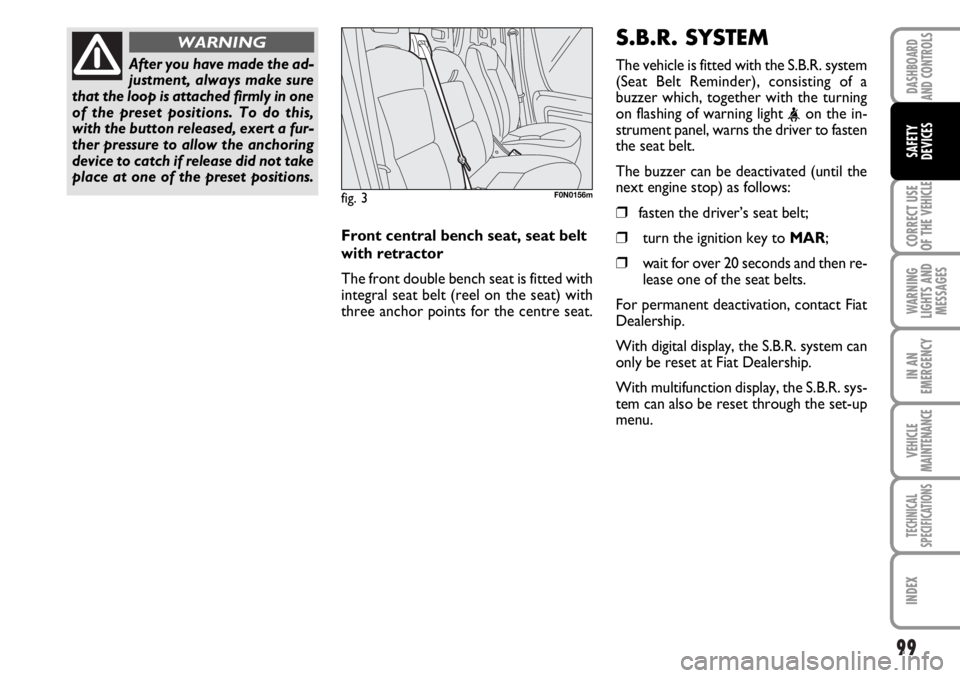
Front central bench seat, seat belt
with retractor
The front double bench seat is fitted with
integral seat belt (reel on the seat) with
three anchor points for the centre seat.
fig. 3F0N0156m
S.B.R. SYSTEM
The vehicle is fitted with the S.B.R. system
(Seat Belt Reminder), consisting of a
buzzer which, together with the turning
on flashing of warning light
the seat belt.
The buzzer can be deactivated (until the
next engine stop) as follows:
❒fasten the driver’s seat belt;
❒turn the ignition key to MAR;
❒wait for over 20 seconds and then re-
lease one of the seat belts.
For permanent deactivation, contact Fiat
Dealership.
With digital display, the S.B.R. system can
only be reset at Fiat Dealership.
With multifunction display, the S.B.R. sys-
tem can also be reset through the set-up
menu.