check engine light FIAT DUCATO 2006 Owner handbook (in English)
[x] Cancel search | Manufacturer: FIAT, Model Year: 2006, Model line: DUCATO, Model: FIAT DUCATO 2006Pages: 238, PDF Size: 3.29 MB
Page 14 of 238
13
SAFETY
DEVICES
CORRECT USE
OF THE
VEHICLE
WARNING
LIGHTS AND
MESSAGES
IN AN
EMERGENCY
VEHICLE
MAINTENANCE
TECHNICAL
SPECIFICATIONS
INDEX
DASHBOARD
AND CONTROLS
IGNITION
DEVICE
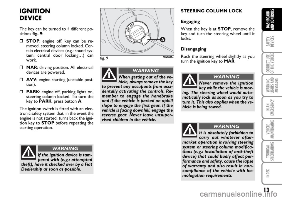
The key can be turned to 4 different po-
sitions fig. 9:
❒STOP: engine off, key can be re-
moved, steering column locked. Cer-
tain electrical devices (e.g.: sound sys-
tem, central door locking…) can
work.
❒MAR: driving position. All electrical
devices are powered.
❒AVV: engine starting (unstable posi-
tion).
❒PARK: engine off, parking lights on,
steering column locked. To turn the
key to PARK, press button A.
The ignition switch is fitted with an elec-
tronic safety system that, in the event the
engine is not started, turns back the igni-
tion key to STOPbefore repeating the
starting operation.STEERING COLUMN LOCK
Engaging
When the key is at STOP, remove the
key and turn the steering wheel until it
locks.
Disengaging
Rock the steering wheel slightly as you
turn the ignition key to MAR.
If the ignition device is tam-
pered with (e.g.: attempted
theft), have it checked over by a Fiat
Dealership as soon as possible.
WARNING
When getting out of the ve-
hicle, always remove the key
to prevent any occupants from acci-
dentally activating the controls. Re-
member to engage the handbrake
and if the vehicle is parked on uphill
slope to engage the first gear. If the
vehicle is facing downhill, engage the
reverse gear. Never leave unsuper-
vised children in the vehicle.
WARNING
fig. 9F0N0007m
Never remove the ignition
key while the vehicle is mov-
ing. The steering wheel would auto-
matically lock as soon as you try to
turn it. This also applies when the ve-
hicle is being towed.
WARNING
It is absolutely forbidden to
carry out whatever after-
market operation involving steering
system or steering column modifica-
tions (e.g.: installation of anti-theft
device) that could badly affect per-
formance and safety, cause the lapse
of warranty and also result in non-
compliance of the vehicle with ho-
mologation requirements.
WARNING
Page 17 of 238
16
SAFETY
DEVICES
CORRECT USE
OF THE
VEHICLE
WARNING
LIGHTS AND
MESSAGES
IN AN
EMERGENCY
VEHICLE
MAINTENANCE
TECHNICAL
SPECIFICATIONS
INDEX
DASHBOARD
AND CONTROLS
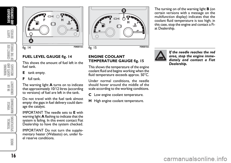
FUEL LEVEL GAUGE fig. 14
This shows the amount of fuel left in the
fuel tank.
Etank empty.
Ffull tank.
The warning light Aturns on to indicate
that approximately 10/12 litres (according
to versions) of fuel are left in the tank.
Do not travel with the fuel tank almost
empty: the gaps in fuel delivery could dam-
age the catalyst.
IMPORTANT The needle sets to Ewith
warning light Aflashing to indicate that the
system is failing. In this event contact Fiat
Dealership to have the system checked.
IMPORTANT Do not turn the supple-
mentary heater (Webasto) on, under fu-
el reserve conditions.ENGINE COOLANT
TEMPERATURE GAUGE fig. 15
This shows the temperature of the engine
coolant fluid and begins working when the
fluid temperature exceeds approx. 50°C.
Under normal conditions, the needle
should hover around the middle of the
scale according to the working conditions.
CLow engine coolant temperature.
HHigh engine coolant temperature.The turning on of the warning light B(on
certain versions with a message on the
multifunction display) indicates that the
coolant fluid temperature is too high; in
this case, stop the engine and contact a Fi-
at Dealership.
fig. 14F0N0014mfig. 15F0N0015m
If the needle reaches the red
area, stop the engine imme-
diately and contact a Fiat
Dealership.
Page 18 of 238
17
SAFETY
DEVICES
CORRECT USE
OF THE
VEHICLE
WARNING
LIGHTS AND
MESSAGES
IN AN
EMERGENCY
VEHICLE
MAINTENANCE
TECHNICAL
SPECIFICATIONS
INDEX
DASHBOARD
AND CONTROLS
ENGINE OIL LEVEL GAUGE
This gauge shows the engine oil level.
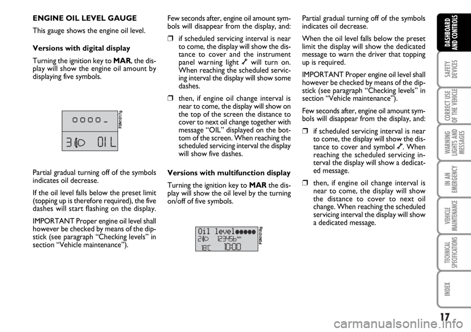
Versions with digital display
Turning the ignition key to MAR, the dis-
play will show the engine oil amount by
displaying five symbols.
F0N1017g
Few seconds after, engine oil amount sym-
bols will disappear from the display, and:
❒if scheduled servicing interval is near
to come, the display will show the dis-
tance to cover and the instrument
panel warning light õwill turn on.
When reaching the scheduled servic-
ing interval the display will show some
dashes.
❒then, if engine oil change interval is
near to come, the display will show on
the top of the screen the distance to
cover to next oil change together with
message “OIL” displayed on the bot-
tom of the screen. When reaching the
scheduled servicing interval the display
will show five dashes.
Versions with multifunction display
Turning the ignition key to MARthe dis-
play will show the oil level by the turning
on/off of five symbols.
F0N1018g
Partial gradual turning off of the symbols
indicates oil decrease.
When the oil level falls below the preset
limit the display will show the dedicated
message to warn the driver that topping
up is required.
IMPORTANT Proper engine oil level shall
however be checked by means of the dip-
stick (see paragraph “Checking levels” in
section “Vehicle maintenance”).
Few seconds after, engine oil amount sym-
bols will disappear from the display, and:
❒if scheduled servicing interval is near
to come, the display will show the dis-
tance to cover and symbol õ. When
reaching the scheduled servicing in-
terval the display will show a dedicat-
ed message.
❒then, if engine oil change interval is
near to come, the display will show
the distance to cover to next oil
change. When reaching the scheduled
servicing interval the display will show
a dedicated message. Partial gradual turning off of the symbols
indicates oil decrease.
If the oil level falls below the preset limit
(topping up is therefore required), the five
dashes will start flashing on the display.
IMPORTANT Proper engine oil level shall
however be checked by means of the dip-
stick (see paragraph “Checking levels” in
section “Vehicle maintenance”).
Page 54 of 238
53
SAFETY
DEVICES
CORRECT USE
OF THE
VEHICLE
WARNING
LIGHTS AND
MESSAGES
IN AN
EMERGENCY
VEHICLE
MAINTENANCE
TECHNICAL
SPECIFICATIONS
INDEX
DASHBOARD
AND CONTROLS
In cold weather, the supplementary heater
warms and circulates constant tempera-
ture fluid in the engine cooling system for
the time required to ensure optimal en-
gine ignition and passenger compartment
temperature conditions.
The heater can be started automatically
(programmed by means of the digital
timer) or manually by pressing the “heat
now” button on the timer.
When the heater is turned on (automat-
ically or manually), the electronic control
unit operates the fluid circulation pump
and safely ignites the burner according to
preset and controlled modes.
❒control unit connected to the
heater/ventilation unit for automatic
operation;
❒electronic control unit to check and
adjusted the integrated heater burner;
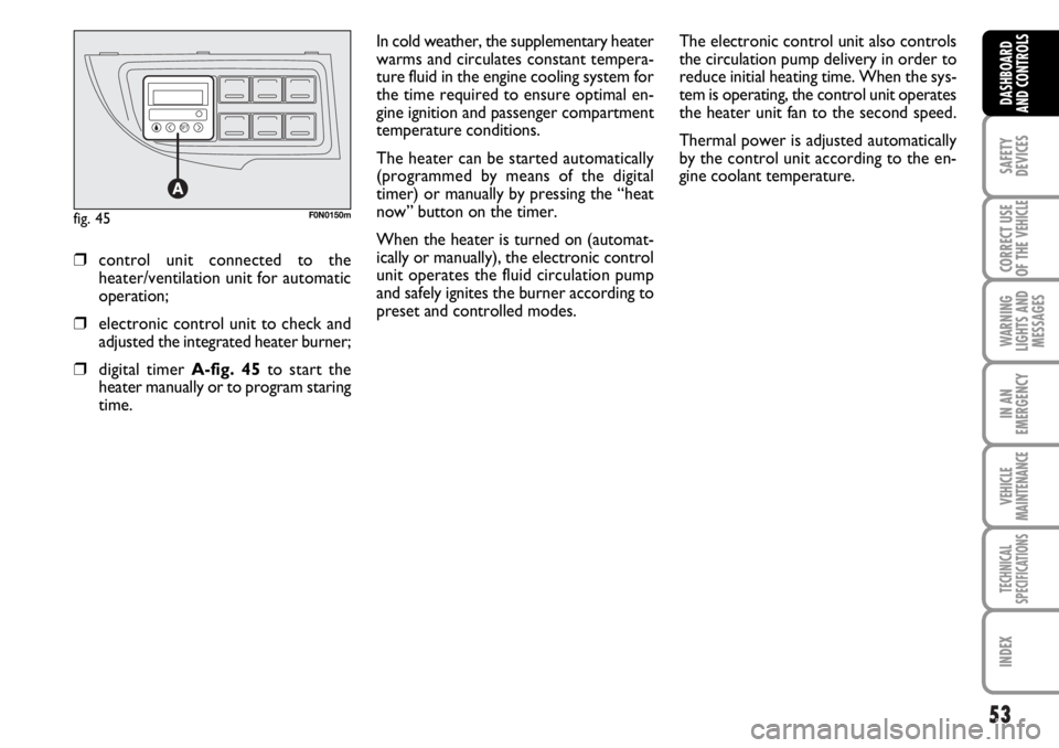
❒digital timer A-fig. 45to start the
heater manually or to program staring
time.The electronic control unit also controls
the circulation pump delivery in order to
reduce initial heating time. When the sys-
tem is operating, the control unit operates
the heater unit fan to the second speed.
Thermal power is adjusted automatically
by the control unit according to the en-
gine coolant temperature.
fig. 45F0N0150m
Page 55 of 238
54
SAFETY
DEVICES
CORRECT USE
OF THE
VEHICLE
WARNING
LIGHTS AND
MESSAGES
IN AN
EMERGENCY
VEHICLE
MAINTENANCE
TECHNICAL
SPECIFICATIONS
INDEX
DASHBOARD
AND CONTROLS
IMPORTANT The heater is equipped with
a thermal switch which cuts off the heater
in the event of overheating caused by low
or leaking coolant. In this case, press the
program selection button to start the
heater again after repairing the cooling sys-
tem fault and/or topping up the fluid.
The heater can turn itself off after engine
ignition or if the flame goes out. In this
case, turn the heater off manually and at-
tempt to turn it back on again. If you can-
not turn the heater on, contact a Fiat
Dealership.Turning the heater on
To obtain max. performance from the
heater unit check that he heating/ventila-
tion unit knob is turned to “warm air”.
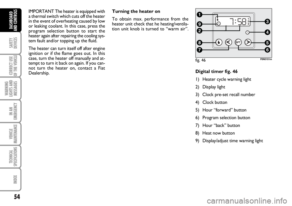
Digital timer fig. 46
1) Heater cycle warning light
2) Display light
3) Clock pre-set recall number
4) Clock button
5) Hour “forward” button
6) Program selection button
7) Hour “back” button
8) Heat now button
9) Display/adjust time warning light
fig. 46F0N0151m
Page 58 of 238
57
SAFETY
DEVICES
CORRECT USE
OF THE
VEHICLE
WARNING
LIGHTS AND
MESSAGES
IN AN
EMERGENCY
VEHICLE
MAINTENANCE
TECHNICAL
SPECIFICATIONS
INDEX
DASHBOARD
AND CONTROLS
❒Always remember to turn the heater
off when refuelling or standing in ser-
vice stations to avoid fires and explo-
sions.
❒Do not park the vehicle over inflam-
mable material such as paper, dry grass
or leaves: fire risk!
❒The temperature near the heater must
never exceed 120°C (e.g. during paint-
ing operations in a workshop oven).
Higher temperatures could damage
the electronic control unit compo-
nents.
❒When the engine is off, the heater takes
power from the battery: it is conse-
quently important to run the engine for
a certain period of time in order to re-
store the battery charge.
❒Follow the prescriptions in section
“Vehicle maintenance” at paragraph
“Engine coolant level” to check the
coolant level. The coolant in the cir-
cuit must contain at least 10% an-
tifreeze fluid.
❒Maintenance and repairs must always
be carried out by a Fiat Dealership and
only genuine spare parts must be used.
MAINTENANCE
Have the heater checked at a Fiat Deal-
ership periodically (always before winter).
This will ensure safe and cheap running
and long appliance life.
The heater burns fuel in the
same way as the engine,
though, of course, to a lesser degree
and therefore to avoid intoxication
and suffocation, never use the sup-
plementary heater in closed areas,
garages or workshops not equipped
with specific exhaust evacuation de-
vices even for short periods of time.
WARNING
Page 63 of 238
62
SAFETY
DEVICES
CORRECT USE
OF THE
VEHICLE
WARNING
LIGHTS AND
MESSAGES
IN AN
EMERGENCY
VEHICLE
MAINTENANCE
TECHNICAL
SPECIFICATIONS
INDEX
DASHBOARD
AND CONTROLS
RAIN SENSOR
(where provided)
The rain sensor is located behind the dri-
ving mirror in contact with the windscreen
and has the purpose of automatically ad-
just, during the intermittent operation, the
frequency of the windscreen wiper
strokes as to the rain intensity.
IMPORTANT Keep clean the glass in the
sensor area.
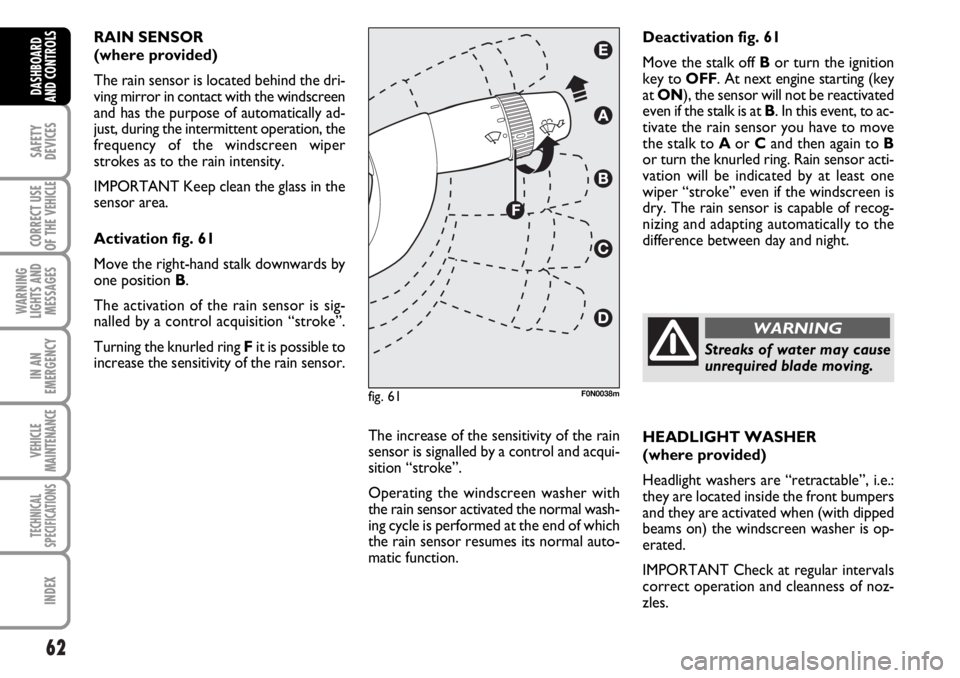
Activation fig. 61
Move the right-hand stalk downwards by
one position B.
The activation of the rain sensor is sig-
nalled by a control acquisition “stroke”.
Turning the knurled ring Fit is possible to
increase the sensitivity of the rain sensor.
The increase of the sensitivity of the rain
sensor is signalled by a control and acqui-
sition “stroke”.
Operating the windscreen washer with
the rain sensor activated the normal wash-
ing cycle is performed at the end of which
the rain sensor resumes its normal auto-
matic function.HEADLIGHT WASHER
(where provided)
Headlight washers are “retractable”, i.e.:
they are located inside the front bumpers
and they are activated when (with dipped
beams on) the windscreen washer is op-
erated.
IMPORTANT Check at regular intervals
correct operation and cleanness of noz-
zles. Deactivation fig. 61
Move the stalk off Bor turn the ignition
key to OFF. At next engine starting (key
at ON), the sensor will not be reactivated
even if the stalk is at B. In this event, to ac-
tivate the rain sensor you have to move
the stalk to Aor Cand then again to B
or turn the knurled ring. Rain sensor acti-
vation will be indicated by at least one
wiper “stroke” even if the windscreen is
dry. The rain sensor is capable of recog-
nizing and adapting automatically to the
difference between day and night.
fig. 61F0N0038m
Streaks of water may cause
unrequired blade moving.
WARNING
Page 65 of 238
64
SAFETY
DEVICES
CORRECT USE
OF THE
VEHICLE
WARNING
LIGHTS AND
MESSAGES
IN AN
EMERGENCY
VEHICLE
MAINTENANCE
TECHNICAL
SPECIFICATIONS
INDEX
DASHBOARD
AND CONTROLS
TO INCREASE THE MEMORISED
SPEED
The speed memorised can be increased in
two ways:
❒pressing the accelerator and then
memorising the new speed reached;
or
❒moving the stalk upwards (+).
Each operation of the stalk will corre-
spond to a slight increase in speed (about
1 km/h), while keeping the stalk upwards
will correspond to a continuous speed in-
crease.
TO REDUCE MEMORISED
SPEED
The speed memorised can be increased in
two ways:
❒disengaging the device and then mem-
orising the new speed;
or
❒moving the stalk downwards (–) until
reaching the new speed which will be
memorised automatically.
Each operation of the stalk will corre-
spond to a slight reduction in speed (about
1 km/h), while keeping the stalk down-
wards will correspond to a continuous
speed reduction.DEVICE DISENGAGEMENT
The device can be disengaged in the fol-
lowing ways:
❒turning the knurled ring Ato OFF;
❒turning the engine off;
❒pressing the brake pedal or engaging
the hand brake;
❒pressing the clutch pedal;
❒shifting gear with automatic transmis-
sion in sequential mode;
❒with vehicle speed below the preset
limit;
❒pressing the accelerator pedal; in this
case the system is not really disen-
gaged but the request for acceleration
takes priority over the system. The
cruise control is however active and it
will not be necessary to press button
RES to resume previous conditions
after ending acceleration.The device is automatically deactivated in
one of the following cases:
❒ABS or ESP system cut-in;
❒system failure.
When travelling with the de-
vice on, never set the
gearshift lever to neutral.
In the event of device mal-
function or failure, turn the
knurled ring A to OFF and contact a
Fiat Dealership after checking the
protection fuse integrity.
WARNING
WARNING
Page 82 of 238
81
SAFETY
DEVICES
CORRECT USE
OF THE
VEHICLE
WARNING
LIGHTS AND
MESSAGES
IN AN
EMERGENCY
VEHICLE
MAINTENANCE
TECHNICAL
SPECIFICATIONS
INDEX
DASHBOARD
AND CONTROLS
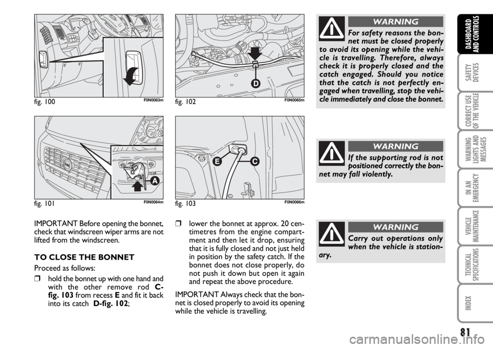
fig. 100F0N0063m
fig. 101F0N0064m
fig. 102F0N0065m
IMPORTANT Before opening the bonnet,
check that windscreen wiper arms are not
lifted from the windscreen.
TO CLOSE THE BONNET
Proceed as follows:
❒hold the bonnet up with one hand and
with the other remove rod C-
fig. 103 from recess Eand fit it back
into its catch D-fig. 102;
❒lower the bonnet at approx. 20 cen-
timetres from the engine compart-
ment and then let it drop, ensuring
that it is fully closed and not just held
in position by the safety catch. If the
bonnet does not close properly, do
not push it down but open it again
and repeat the above procedure.
IMPORTANT Always check that the bon-
net is closed properly to avoid its opening
while the vehicle is travelling.
fig. 103F0N0066m
For safety reasons the bon-
net must be closed properly
to avoid its opening while the vehi-
cle is travelling. Therefore, always
check it is properly closed and the
catch engaged. Should you notice
that the catch is not perfectly en-
gaged when travelling, stop the vehi-
cle immediately and close the bonnet.
WARNING
If the supporting rod is not
positioned correctly the bon-
net may fall violently.
WARNING
Carry out operations only
when the vehicle is station-
ary.
WARNING
Page 86 of 238
85
SAFETY
DEVICES
CORRECT USE
OF THE
VEHICLE
WARNING
LIGHTS AND
MESSAGES
IN AN
EMERGENCY
VEHICLE
MAINTENANCE
TECHNICAL
SPECIFICATIONS
INDEX
DASHBOARD
AND CONTROLS
BRAKE ASSIST
(emergency braking assistance
integral with ESP) (where provided)
The system, which cannot be cut out, rec-
ognizes emergency braking (on the ground
of the brake pedal operation speed) and
considerably increases the pressure in the
brake circuit.
Brake Assist is deactivated on the versions
equipped with ESP, in the event of ESP sys-
tem failure (indicated by warning light
áswitching on together with the message
on the multifunction display, where pro-
vided).
ESP SYSTEM
(Electronic Stability
Program)
(where provided)
The ESP system is an electronic system
controlling the vehicle stability in the event
of tyre grip loss.
The ESP system is therefore particularly
useful when grip conditions of the road sur-
faces changes.
In addition to the ESP system, ASR system
and Hill Holder, (where provided) also the
MSR system (adjusting the engine braking
torque) and the HBA system (improving
the braking force during emergency brak-
ing) are provided.
ESP SYSTEM INTERVENTION
It is signalled by the blinking of the warn-
ing light áon the instrument panel, to in-
form the driver that the vehicle is in crit-
ical stability and grip conditions.
When the ABS cuts in, and
you feel the brake pedal pul-
sating, do not remove your foot, but
keep it pressed; in doing so you will
stop in the shortest amount of space
possible under the current road con-
ditions.
WARNING
EBD failure
EBD failure is indicated by the turning on
of warning lights
>and xon the in-
strument panel together with the dedi-
cated message on the multifunction dis-
play (where provided), (see section
“Warning lights and messages”).
In this case with sharp braking the rear
wheels might lock too early, with the pos-
sibility of skidding. Drive extremely care-
fully to the nearest Fiat Dealership to have
the system checked.
If warning light xalone
comes on (together with the
message on the multifunction display,
where provided), stop the vehicle im-
mediately and contact the nearest Fi-
at Dealership. Fluid leaks from the hy-
draulic system, in fact, can compro-
mise the braking system, both tradi-
tional systems and systems with ABS.
WARNING