technical specifications FIAT DUCATO 2007 Owner handbook (in English)
[x] Cancel search | Manufacturer: FIAT, Model Year: 2007, Model line: DUCATO, Model: FIAT DUCATO 2007Pages: 282, PDF Size: 4.49 MB
Page 155 of 282
154
IN AN
EMERGENCY
VEHICLE
MAINTENANCE
TECHNICAL
SPECIFICATIONS
INDEX
DASHBOARD
AND CONTROLS
SAFETY
DEVICES
CORRECT USE
OF THE
VEHICLE
WARNING
LIGHTS AND
MESSAGES
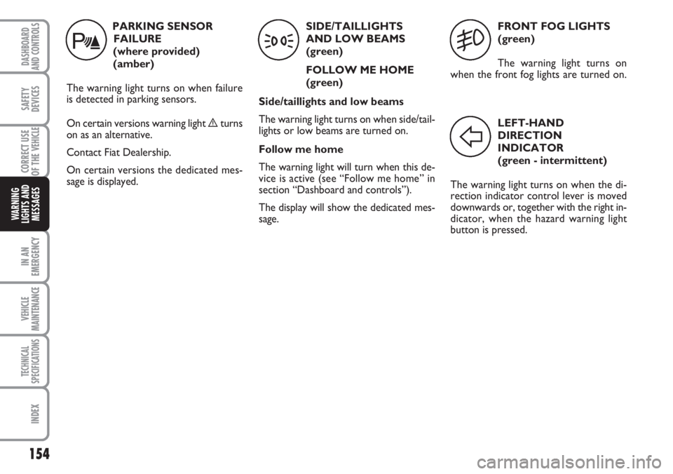
FRONT FOG LIGHTS
(green)
The warning light turns on
when the front fog lights are turned on.
5
LEFT-HAND
DIRECTION
INDICATOR
(green - intermittent)
The warning light turns on when the di-
rection indicator control lever is moved
downwards or, together with the right in-
dicator, when the hazard warning light
button is pressed.
F
PARKING SENSOR
FAILURE
(where provided)
(amber)
The warning light turns on when failure
is detected in parking sensors.
On certain versions warning light èturns
on as an alternative.
Contact Fiat Dealership.
On certain versions the dedicated mes-
sage is displayed.
t
SIDE/TAILLIGHTS
AND LOW BEAMS
(green)
FOLLOW ME HOME
(green)
Side/taillights and low beams
The warning light turns on when side/tail-
lights or low beams are turned on.
Follow me home
The warning light will turn when this de-
vice is active (see “Follow me home” in
section “Dashboard and controls”).
The display will show the dedicated mes-
sage.
3
Page 156 of 282
155
IN AN
EMERGENCY
VEHICLE
MAINTENANCE
TECHNICAL
SPECIFICATIONS
INDEX
DASHBOARD
AND CONTROLS
SAFETY
DEVICES
CORRECT USE
OF THE
VEHICLE
WARNING
LIGHTS AND
MESSAGES
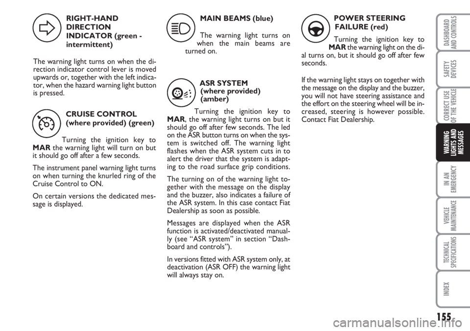
CRUISE CONTROL
(where provided) (green)
Turning the ignition key to
MARthe warning light will turn on but
it should go off after a few seconds.
The instrument panel warning light turns
on when turning the knurled ring of the
Cruise Control to ON.
On certain versions the dedicated mes-
sage is displayed.
Ü
MAIN BEAMS (blue)
The warning light turns on
when the main beams are
turned on.
1
RIGHT-HAND
DIRECTION
INDICATOR (green -
intermittent)
The warning light turns on when the di-
rection indicator control lever is moved
upwards or, together with the left indica-
tor, when the hazard warning light button
is pressed.
D
ASR SYSTEM
(where provided)
(amber)
Turning the ignition key to
MAR, the warning light turns on but it
should go off after few seconds. The led
on the ASR button turns on when the sys-
tem is switched off. The warning light
flashes when the ASR system cuts in to
alert the driver that the system is adapt-
ing to the road surface grip conditions.
The turning on of the warning light to-
gether with the message on the display
and the buzzer, also indicates a failure of
the ASR system. In this case contact Fiat
Dealership as soon as possible.
Messages are displayed when the ASR
function is activated/deactivated manual-
ly (see “ASR system” in section “Dash-
board and controls”).
In versions fitted with ASR system only, at
deactivation (ASR OFF) the warning light
will always stay on.
V
POWER STEERING
FAILURE (red)
Turning the ignition key to
MARthe warning light on the di-
al turns on, but it should go off after few
seconds.
If the warning light stays on together with
the message on the display and the buzzer,
you will not have steering assistance and
the effort on the steering wheel will be in-
creased, steering is however possible.
Contact Fiat Dealership.
g
Page 157 of 282
156
IN AN
EMERGENCY
VEHICLE
MAINTENANCE
TECHNICAL
SPECIFICATIONS
INDEX
DASHBOARD
AND CONTROLS
SAFETY
DEVICES
CORRECT USE
OF THE
VEHICLE
WARNING
LIGHTS AND
MESSAGES
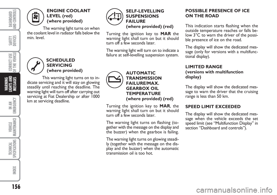
AUTOMATIC
TRANSMISSION
FAILURE/MAX.
GEARBOX OIL
TEMPERATURE
(where provided) (red)
Turning the ignition key to MAR, the
warning light shall turn on but it should
turn off a few seconds later.
The warning light turns on flashing (to-
gether with the message on the display and
the buzzer) when the gearbox is failing.
The warning light turns on glowing steadi-
ly (together with the message on the dis-
play and the buzzer) when the automatic
transmission oil is too hot. SCHEDULED
SERVICING
(where provided)
This warning light turns on to in-
dicate servicing and it will stay on glowing
steadily until reaching the deadline. The
warning light will turn off after carrying out
servicing at Fiat Dealership or after 1000
km at servicing deadline.SELF-LEVELLING
SUSPENSIONS
FAILURE
(where provided) (red)
Turning the ignition key to MARthe
warning light shall turn on but it should
turn off a few seconds later.
The warning light will turn on to indicate a
failure at self-levelling suspension system.POSSIBLE PRESENCE OF ICE
ON THE ROAD
This indication starts flashing when the
outside temperature reaches or falls be-
low 3°C to warn the driver of the possi-
ble presence of ice on the road.
The display will show the dedicated mes-
sage (only for versions with a multifunc-
tional display).
LIMITED RANGE
(versions with multifunction
display)
The display will show the dedicated mes-
sage to warn the driver that the cruising
range is less than 50 km.
SPEED LIMIT EXCEEDED
The display will show the dedicated mes-
sage when the vehicle exceeds the set
speed limit (see “Multifunction Display” in
section “Dashboard and controls”). ENGINE COOLANT
LEVEL (red)
(where provided)
The warning light turns on when
the coolant level in radiator falls below the
min. level.
n
õ
Œ
t
Page 158 of 282
157
WARNING
LIGHTS AND
MESSAGES
VEHICLE
MAINTENANCE
TECHNICAL
SPECIFICATIONS
INDEX
DASHBOARD
AND CONTROLS
SAFETY
DEVICES
CORRECT USE
OF THE
VEHICLE
IN AN
EMERGENCY
ENGINE STARTING ............................................................ 158
IF A TYRE IS PUNCTURED ................................................ 159
QUICK TYRE REPAIR KIT
FIX & GO automatic ............................................................. 163
WHEN NEEDING TO CHANGE A BULB .................... 168
IF AN EXTERIOR LIGHT BURNS OUT .......................... 170
IF AN INTERIOR LIGHT BURNS OUT ........................... 176
IF A FUSE BLOWS ................................................................. 177
IF THE BATTERY IS FLAT ................................................... 185
JACKING THE VEHICLE ..................................................... 186
TOWING THE VEHICLE .................................................... 186
I I
N N
A A
N N
E E
M M
E E
R R
G G
E E
N N
C C
Y Y
Page 159 of 282
158
WARNING
LIGHTS AND
MESSAGES
VEHICLE
MAINTENANCE
TECHNICAL
SPECIFICATIONS
IINDEX
DASHBOARD
AND CONTROLS
SAFETY
DEVICES
CORRECT USE
OF THE
VEHICLE
IN AN
EMERGENCY
ENGINE
STARTING
EMERGENCY START-UP
If the instrument panel warning light
Yturns on glowing steadily, contact im-
mediately Fiat Dealership.
JUMP STARTING fig. 1-2
If the battery is flat, it is possible to start
the engine using an auxiliary battery with
the same capacity or a little higher than
the flat one.
Contact Fiat Dealership to have the bat-
tery checked/replaced.Proceed as follows:
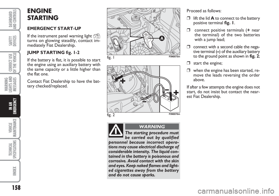
❒lift the lid Ato connect to the battery
positive terminal fig. 1.
❒connect positive terminals (+near
the terminal) of the two batteries
with a jump lead;
❒connect with a second cable the nega-
tive terminal (–) of the auxiliary battery
to the ground point as shown in fig. 2;
❒start the engine;
❒when the engine has been started, re-
move the leads reversing the order
above.
If after a few attempts the engine does not
start, do not insist but contact the near-
est Fiat Dealership.
fig. 1F0N0075m
The starting procedure must
be carried out by qualified
personnel because incorrect opera-
tions may cause electrical discharge of
considerable intensity. The liquid con-
tained in the battery is poisonous and
corrosive. Avoid contact with the skin
and eyes. Keep naked flames and light-
ed cigarettes away from the battery
and do not cause sparks.
WARNING
fig. 2F0N0076m
Page 160 of 282
159
WARNING
LIGHTS AND
MESSAGES
VEHICLE
MAINTENANCE
TECHNICAL
SPECIFICATIONS
INDEX
DASHBOARD
AND CONTROLS
SAFETY
DEVICES
CORRECT USE
OF THE
VEHICLE
IN AN
EMERGENCY
IMPORTANT Do not directly connect the
negative terminals of the two batteries:
sparks could ignite the flammable gas from
the battery. If the other battery is fitted in
another vehicle, prevent accidental con-
tacts between the metal parts of the two
vehicles.
BUMP STARTING
Never bump start the engine (by pushing,
towing, or coasting downhill) as this could
cause fuel to flow into the catalytic ex-
haust system and damage it beyond repair.
IMPORTANT Remember that the brake
booster and the power steering system
are not operating until the engine is start-
ed, a greater effort will therefore be re-
quired to press the brake pedal or turn
the steering wheel.IF A TYRE
IS PUNCTURED
GENERAL INSTRUCTIONS
Wheel changing and correct use of the
jack and spare wheel call for some pre-
cautions as listed below.
Alert other drivers that the
vehicle is stationary in com-
pliance with the regulations in force:
hazard warning lights, warning trian-
gle etc. Any passengers on board
should leave the vehicle, especially if
it is heavily laden. Passengers should
stay away from oncoming traffic
while the wheel is being changed on.
Pull the handbrake.
WARNING
The spare wheel is specific to
your vehicle, do not use it on
other models, or use the spare wheel
of other models on your vehicle.
Wheel bolts are specific to your vehi-
cle: do not use them on other models
and do not use bolts of other models.
WARNING
Have the punctured wheel
repaired and refitted as soon
as possible. Do not grease the threads
of bolts before installing them: they
might slip out.
WARNING
Page 161 of 282
160
WARNING
LIGHTS AND
MESSAGES
VEHICLE
MAINTENANCE
TECHNICAL
SPECIFICATIONS
IINDEX
DASHBOARD
AND CONTROLS
SAFETY
DEVICES
CORRECT USE
OF THE
VEHICLE
IN AN
EMERGENCY
To change a wheel proceed as
follows:
❒stop the vehicle in a position that is
not dangerous for oncoming traffic
where you can change the wheel safe-
ly. The ground should be flat and ad-
equately firm;
❒turn the engine off and pull up the
handbrake;
❒engage first gear or reverse;
❒wear the reflecting safety jacket (com-
pulsory by law in certain countries) be-
fore getting out of the vehicle;
❒alert other drivers that the vehicle is
stationary, using the proper devices in
compliance with the regulations in
force (e.g.: warning triangle, hazard
warning lights, etc …);
❒take the extension and the wrench
from the tool bag under the passen-
ger’s seat (see “Compartment under
the front passenger’s seat” in section
“dashboard and controls”);
The jack shall only be used
for changing wheels on the
vehicle with which it is provided or on
vehicles of the same model. It must
not be used for other purposes such
as for instance raising vehicles of oth-
er models. In no case should it be used
for repairs under the vehicle. Incor-
rect positioning of the jack may cause
the jacked vehicle to fall. Do not use
the jack for higher capacities than
stated on its label.
WARNING
Never tamper with the in-
flation valve. Never place
tools between the rim and tyre.
Check and restore, if required, the
pressure of tyres and spare wheel to
the values given in section “Technical
Specifications”.
WARNING
Please note:
❒the jack weight is 4,5 kg;
❒the jack requires no adjustment;
❒the jack cannot be repaired. If it breaks
it must be replaced with a new jack;
❒no tool other than its cranking device
may be fitted on the jack.
fig. 3F0N0193m
Page 162 of 282
161
WARNING
LIGHTS AND
MESSAGES
VEHICLE
MAINTENANCE
TECHNICAL
SPECIFICATIONS
INDEX
DASHBOARD
AND CONTROLS
SAFETY
DEVICES
CORRECT USE
OF THE
VEHICLE
IN AN
EMERGENCY
❒on versions with alloy wheels, remote
the press-fitted hub cap;
❒loosen one turn the bolts of the wheel
to change;
❒turn the ring nut to extend the jack
partially;
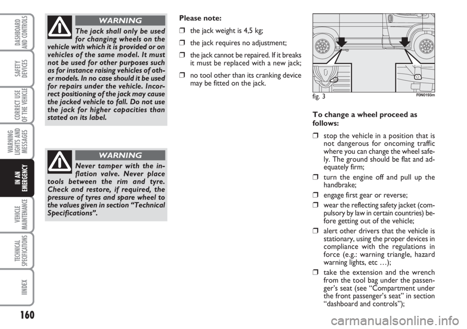
❒set the jack near the lifting support
close to the wheel to change in the
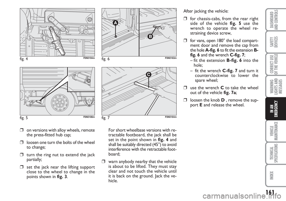
points shown in fig. 3. For short wheelbase versions with re-
tractable footboard, the jack shall be
set in the point shown in fig. 4and
shall be suitably directed (45°) to avoid
interference with the retractable foot-
board;
❒warn anybody nearby that the vehicle
is about to be lifted. They must stay
clear and not touch the vehicle until
it is back on the ground. Jack the ve-
hicle.
fig. 4F0N0194m
fig. 5F0N0186m
fig. 6F0N0163m
fig. 7F0N0164m
After jacking the vehicle:
❒for chassis-cabs, from the rear right
side of the vehicle fig. 5use the
wrench to operate the wheel re-
straining device screw,
❒for vans, open 180° the load compart-
ment door and remove the cap from
the hole A-fig. 6to fit the extension B-
fig. 6and the wrench C-fig. 7;
– fit the extension B-fig. 6into the
hole;
– fit the wrench C-fig. 7and turn it
counterclockwise to lower the
spare wheel;
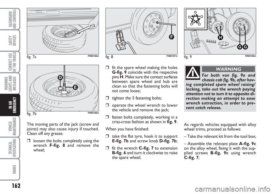
❒use the wrench Cto take the wheel
out of the vehicle fig. 7a;
❒loosen the knob D , remove the sup-
port Eand release the wheel.
Page 163 of 282
162
WARNING
LIGHTS AND
MESSAGES
VEHICLE
MAINTENANCE
TECHNICAL
SPECIFICATIONS
IINDEX
DASHBOARD
AND CONTROLS
SAFETY
DEVICES
CORRECT USE
OF THE
VEHICLE
IN AN
EMERGENCY
❒fit the spare wheel making the holes
G-fig. 9coincide with the respective
pins H. Make sure the contact surfaces
between spare wheel and hub are
clean so that the fastening bolts will
not come loose;
❒tighten the 5 fastening bolts;
❒operate the wheel wrench to lower
the vehicle and remove the jack;
❒fasten bolts completely, working in a
criss-cross fashion as shown in fig. 9.
When you have finished:
❒take the flat tyre, hook it to support
E-fig. 7band screw knob D-fig. 7b;
❒fit the wrench C-fig. 7to extension
B-fig. 6and turn it clockwise to raise
the spare wheel;
fig. 8F0N0167mfig. 9F0N0168m
The moving parts of the jack (screw and
joints) may also cause injury if touched.
Clean off any grease.
❒loosen the bolts completely using the
wrench F-fig. 8and remove the
wheel;
fig. 7aF0N0165m
fig. 7bF0N0166m
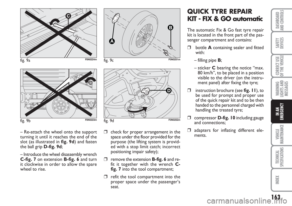
For both van fig. 9a and
chassis cab fig. 9b, after hav-
ing completed spare wheel raising/
locking, take out the wrench paying
attention not to turn it to opposite di-
rection making an attempt to ease
wrench extraction, in order to pre-
vent catch release.
WARNING
As regards vehicles equipped with alloy
wheel trims, proceed as follows:
– Take the relevant kit from the tool box;
– Assemble the relevant plate A-fig. 9c
on the alloy wheel, fixing it with the sup-
plied screws B-fig. 9cusing wrench
C-fig. 7;
Page 164 of 282
163
WARNING
LIGHTS AND
MESSAGES
VEHICLE
MAINTENANCE
TECHNICAL
SPECIFICATIONS
INDEX
DASHBOARD
AND CONTROLS
SAFETY
DEVICES
CORRECT USE
OF THE
VEHICLE
IN AN
EMERGENCY
QUICK TYRE REPAIR
KIT - FIX & GO automatic
The automatic Fix & Go fast tyre repair
kit is located in the front part of the pas-
senger compartment and contains:
❒bottle A containing sealer and fitted
with:
– filling pipe B;
– sticker Cbearing the notice “max.
80 km/h”, to be placed in a position
visible to the driver (on the instru-
ment panel) after fixing the tyre;
❒instruction brochure (see fig. 11), to
be used for prompt and proper use
of the quick repair kit and to be then
handed to the personnel charged with
handling the treated tyre;
❒compressor D-fig. 10including gauge
and connections;
❒adapters for inflating different ele-
ments.❒check for proper arrangement in the
space under the floor provided for the
purpose (the lifting system is provid-
ed with a stop limit catch; incorrect
positioning impair safety);
❒remove the extension B-fig. 6and re-
fit it together with the wrench C-
fig. 7into the tool compartment;
❒refit the tool compartment into the
proper space under the passenger’s
seat.
fig. 9aF0N0224m
fig. 9bF0N0223m
– Re-attach the wheel onto the support
turning it until it reaches the end of the
slot (as illustrated in fig. 9d) and fasten
the ball grip D-fig. 9d;
– Introduce the wheel disassembly wrench
C-fig. 7on extension B-fig. 6and turn
it clockwise in order to allow the spare
wheel to rise.
fig. 9cF0N0251m
fig. 9dF0N0252m