technical specifications FIAT DUCATO 2010 Owner handbook (in English)
[x] Cancel search | Manufacturer: FIAT, Model Year: 2010, Model line: DUCATO, Model: FIAT DUCATO 2010Pages: 286, PDF Size: 12.53 MB
Page 44 of 286
43
KNOWING
YOUR CAR
SAFETY
STARTING
AND
DRIVING
WARNING
LIGHTS AND
MESSAGES
IN AN
EMERGENCY
MAINTENANCE
AND CARE
TECHNICAL
SPECIFICATIONS
INDEX
F0N0238mfig. 38
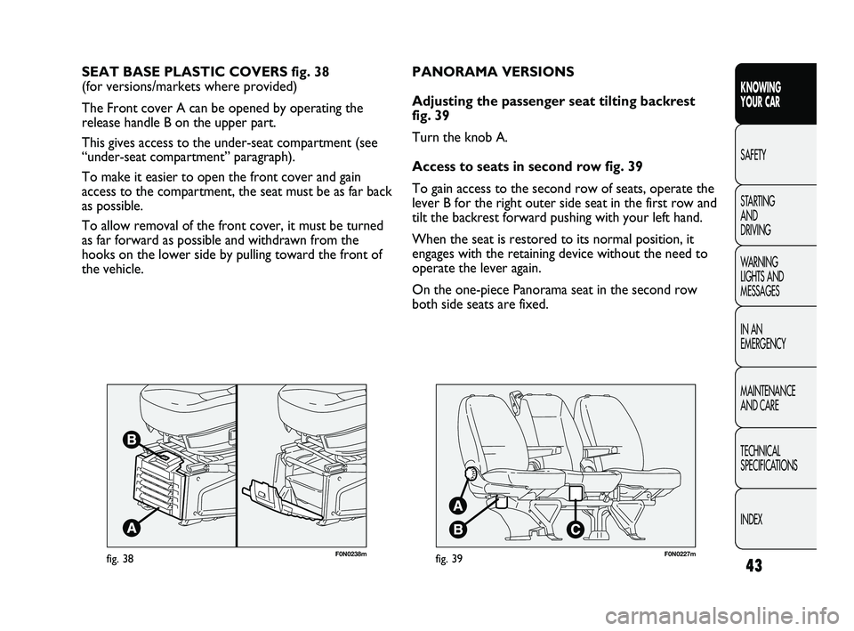
SEAT BASE PLASTIC COVERS fig. 38
(for versions/markets where provided)
The Front cover A can be opened by operating the
release handle B on the upper part.
This gives access to the under-seat compartment (see
“under-seat compartment” paragraph).
To make it easier to open the front cover and gain
access to the compartment, the seat must be as far back
as possible.
To allow removal of the front cover, it must be turned
as far forward as possible and withdrawn from the
hooks on the lower side by pulling toward the front of
the vehicle.
F0N0227mfig. 39
PANORAMA VERSIONS
Adjusting the passenger seat tilting backrest
fig. 39
Turn the knob A.
Access to seats in second row fig. 39
To gain access to the second row of seats, operate the
lever B for the right outer side seat in the first row and
tilt the backrest forward pushing with your left hand.
When the seat is restored to its normal position, it
engages with the retaining device without the need to
operate the lever again.
On the one-piece Panorama seat in the second row
both side seats are fixed.
037-128 DUCATO LUM EN 7ed 6/21/10 2:10 PM Page 43
Page 45 of 286
44
KNOWING
YOUR CAR
SAFETY
STARTING
AND
DRIVING
WARNING
LIGHTS AND
MESSAGES
IN AN
EMERGENCY
MAINTENANCE
AND CARE
TECHNICAL
SPECIFICATIONS
INDEX
F0N0229mfig. 41
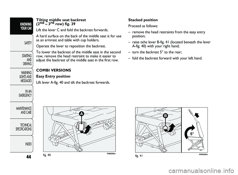
Stacked position
Proceed as follows:
– remove the head restraints from the easy entry
position;
– raise txhe lever B-fig. 41 (located beneath the lever
A-fig. 40) with your right hand;
– turn the backrest 5° to the rear;
– fold the backrest forward with your left hand.
F0N0228mfig. 40
Tilting middle seat backrest
(2nd
–3rd
row) fig. 39
Lift the lever C and fold the backrest forwards.
A hard surface on the back of the middle seat is for use
as an armrest and table with cup holders.
Operate the lever to reposition the backrest.
To lower the backrest of the middle seat in the second
row, remove the head restraint to make it easier to
adjust the backrest of the middle seat in the first row.
COMBI VERSIONS
Easy Entry position
Lift lever A-fig. 40 and tilt the backrest forwards.
037-128 DUCATO LUM EN 7ed 6/21/10 2:10 PM Page 44
Page 46 of 286
45
KNOWING
YOUR CAR
SAFETY
STARTING
AND
DRIVING
WARNING
LIGHTS AND
MESSAGES
IN AN
EMERGENCY
MAINTENANCE
AND CARE
TECHNICAL
SPECIFICATIONS
INDEX
F0N0230mfig. 42
Do not travel with passengers seated in
the 3rd row with the 2nd row bench
folded over. Do not place objects of any type
on the backrest of the 2nd bench with the row
folded over: in the event of impact or sharp
braking they could be thrown against the
occupants of the vehicle casing serious injury.
For more information, see the contents of the
adhesive plate located under the bench.
WARNING
Removing the bench
IMPORTANT At least two people must be present to
remove the bench.
F0N0231mfig. 43
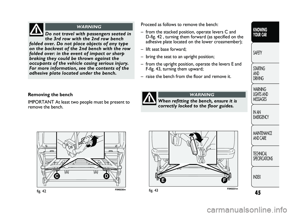
Proceed as follows to remove the bench:
– from the stacked position, operate levers C and
D-fig. 42 , turning them forward (as specified on the
adhesive plate located on the lower crossmember);
– lift seat base forward;
– bring the seat to an upright position;
– from the upright position, operate the levers E and
F-fig. 43, turning them upward;
– raise the bench from the floor and remove it.
When refitting the bench, ensure it is
correctly locked to the floor guides.
WARNING
037-128 DUCATO LUM EN 7ed 6/21/10 2:10 PM Page 45
Page 47 of 286
46
KNOWING
YOUR CAR
SAFETY
STARTING
AND
DRIVING
WARNING
LIGHTS AND
MESSAGES
IN AN
EMERGENCY
MAINTENANCE
AND CARE
TECHNICAL
SPECIFICATIONS
INDEX
To make the best use of the head restraint’s protective
action, adjust the backrest so that your torso is upright
and keep your head as close as possible to the head
restraint.
Head restraints must be adjusted so that
the head, rather than the neck, rests on
them. Only in this case they can protect your
head correctly.
WARNING
F0N0020mfig. 44
HEAD RESTRAINTS
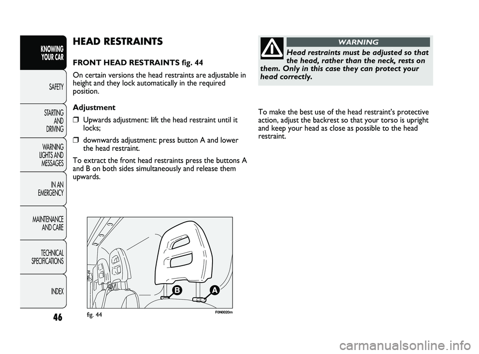
FRONT HEAD RESTRAINTS fig. 44
On certain versions the head restraints are adjustable in
height and they lock automatically in the required
position.
Adjustment
❒Upwards adjustment: lift the head restraint until it
locks;
❒downwards adjustment: press button A and lower
the head restraint.
To extract the front head restraints press the buttons A
and B on both sides simultaneously and release them
upwards.
037-128 DUCATO LUM EN 7ed 6/21/10 2:10 PM Page 46
Page 48 of 286
47
KNOWING
YOUR CAR
SAFETY
STARTING
AND
DRIVING
WARNING
LIGHTS AND
MESSAGES
IN AN
EMERGENCY
MAINTENANCE
AND CARE
TECHNICAL
SPECIFICATIONS
INDEX
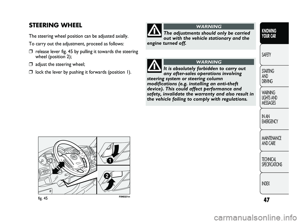
F0N0321mfig. 45
STEERING WHEEL
The steering wheel position can be adjusted axially.
To carry out the adjustment, proceed as follows:
❒release lever fig. 45 by pulling it towards the steering
wheel (position 2);
❒adjust the steering wheel;
❒lock the lever by pushing it forwards (position 1).
The adjustments should only be carried
out with the vehicle stationary and the
engine turned off.
WARNING
It is absolutely forbidden to carry out
any after-sales operations involving
steering system or steering column
modifications (e.g. installing an anti-theft
device). This could affect performance and
safety, invalidate the warranty and also result in
the vehicle failing to comply with regulations.
WARNING
037-128 DUCATO LUM EN 7ed 6/21/10 2:10 PM Page 47
Page 49 of 286
48
KNOWING
YOUR CAR
SAFETY
STARTING
AND
DRIVING
WARNING
LIGHTS AND
MESSAGES
IN AN
EMERGENCY
MAINTENANCE
AND CARE
TECHNICAL
SPECIFICATIONS
INDEX
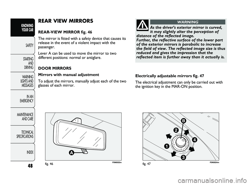
F0N0022mfig. 46F0N0024mfig. 47
Electrically adjustable mirrors fig. 47
The electrical adjustment can only be carried out with
the ignition key in the MAR-ON position.
REAR VIEW MIRRORS
REAR-VIEW MIRROR fig. 46
The mirror is fitted with a safety device that causes its
release in the event of a violent impact with the
passenger.
Lever A can be used to move the mirror to two
different positions: normal or antiglare.
DOOR MIRRORS
Mirrors with manual adjustment
To adjust the mirrors, manually adjust each of the two
glasses of each mirror.
As the driver’s exterior mirror is curved,
it may slightly alter the perception of
distance of the reflected image.
Further, the reflective surface of the lower part
of the exterior mirrors is parabolic to increase
the field of view. The reflected image size is thus
reduced and gives the impression that the
reflected item is further away than it actually is.
WARNING
037-128 DUCATO LUM EN 7ed 6/21/10 2:10 PM Page 48
Page 50 of 286
49
KNOWING
YOUR CAR
SAFETY
STARTING
AND
DRIVING
WARNING
LIGHTS AND
MESSAGES
IN AN
EMERGENCY
MAINTENANCE
AND CARE
TECHNICAL
SPECIFICATIONS
INDEX
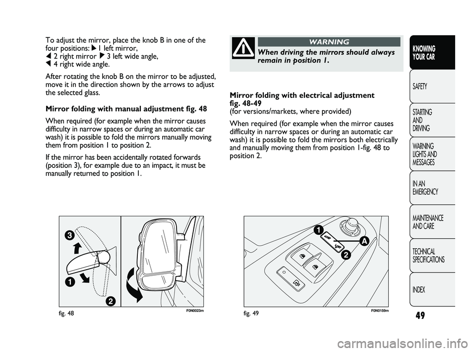
Mirror folding with electrical adjustment
fig. 48-49
(for versions/markets, where provided)
When required (for example when the mirror causes
difficulty in narrow spaces or during an automatic car
wash) it is possible to fold the mirrors both electrically
and manually moving them from position 1-fig. 48 to
position 2. To adjust the mirror, place the knob B in one of the
four positions: ÿ1 left mirror,
⁄2 right mirror ¤3 left wide angle,
Ÿ4 right wide angle.
After rotating the knob B on the mirror to be adjusted,
move it in the direction shown by the arrows to adjust
the selected glass.
Mirror folding with manual adjustment fig. 48
When required (for example when the mirror causes
difficulty in narrow spaces or during an automatic car
wash) it is possible to fold the mirrors manually moving
them from position 1 to position 2.
If the mirror has been accidentally rotated forwards
(position 3), for example due to an impact, it must be
manually returned to position 1.
When driving the mirrors should always
remain in position 1.
WARNING
F0N0023mfig. 48F0N0159mfig. 49
037-128 DUCATO LUM EN 7ed 6/21/10 2:10 PM Page 49
Page 51 of 286
50
KNOWING
YOUR CAR
SAFETY
STARTING
AND
DRIVING
WARNING
LIGHTS AND
MESSAGES
IN AN
EMERGENCY
MAINTENANCE
AND CARE
TECHNICAL
SPECIFICATIONS
INDEX
To bring the mirrors to the opening position electrically,
press point 2 of the rocker button A-fig. 49 until an
engagement “click” is heard, then press point 1 of the
button.
IMPORTANT If the mirrors have been manually folded
by mistake to position 3 – fig. 48, the mirror moves to
an intermediate position. In this case, manually rotate
the mirror to position 1, then press point 2 of the
rocker button A-fig. 49 to return the mirror to position
2 until a “click” is heard, then press point 1 of the
button to bring it back to position 1.
Defrosting/demisting
(for versions/markets where provided)
The mirrors are fitted with resistors that are activated
when the heated rear windscreen is turned on (by
pressing button
().
IMPORTANT This function is timed and it will turn off
automatically a few minutes later. Electric folding
To fold the mirrors electrically, press point 2 of the
rocker button A-fig. 49. To bring the mirrors back to
the open position, press point 1 of the button.
IMPORTANT If the mirrors are folded electrically, they
should be returned to the open position electrically: do
not try to return the mirrors manually to driving
position.
Manual folding
To fold the mirrors manually, move them from position
1-fig. 48 to position 2. If the mirrors are folded
manually, they can be returned to the open position
both manually and electrically.
IMPORTANT To bring the mirrors electrically to the
opening position, press point 2 of the rocker button
A-fig. 49 until an engagement “click” is heard, then press
again point 1 of the button again.
Folding forwards
The mirrors can be manually folded forwards (position
3-fig. 48) or brought to the opening position 2 again
manually if they have been accidentally rotated forwards
(for example due to an impact).
If the mirrors have been rotated forwards manually or
due to an impact, they can be returned to the open
position both manually and electrically.
037-128 DUCATO LUM EN 7ed 6/21/10 2:10 PM Page 50
Page 52 of 286
51
KNOWING
YOUR CAR
SAFETY
STARTING
AND
DRIVING
WARNING
LIGHTS AND
MESSAGES
IN AN
EMERGENCY
MAINTENANCE
AND CARE
TECHNICAL
SPECIFICATIONS
INDEX
fig. 50
F0N0322m
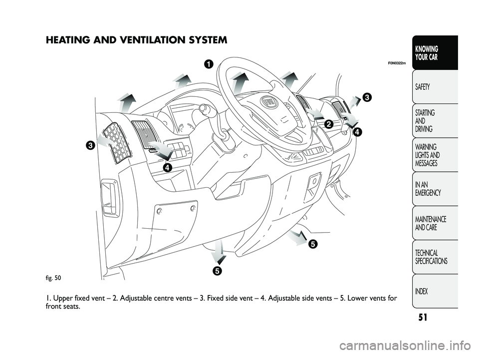
HEATING AND VENTILATION SYSTEM
1. Upper fixed vent – 2. Adjustable centre vents – 3. Fixed side vent – 4. Adjustable side vents – 5. Lower vents for
front seats.
037-128 DUCATO LUM EN 7ed 6/21/10 2:10 PM Page 51
Page 53 of 286
52
KNOWING
YOUR CAR
SAFETY
STARTING
AND
DRIVING
WARNING
LIGHTS AND
MESSAGES
IN AN
EMERGENCY
MAINTENANCE
AND CARE
TECHNICAL
SPECIFICATIONS
INDEX
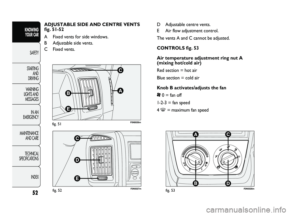
F0N0026mfig. 51
F0N0027mfig. 52F0N0028mfig. 53
D Adjustable centre vents.
E Air flow adjustment control.
The vents A and C cannot be adjusted.
CONTROLS fig. 53
Air temperature adjustment ring nut A
(mixing hot/cold air)
Red section = hot air
Blue section = cold air
Knob B activates/adjusts the fan
p0 = fan off
1-2-3 = fan speed
4
-= maximum fan speed ADJUSTABLE SIDE AND CENTRE VENTS
fig. 51-52
A Fixed vents for side windows.
B Adjustable side vents.
C Fixed vents.
037-128 DUCATO LUM EN 7ed 6/21/10 2:10 PM Page 52