roof FIAT DUCATO 2012 Owner handbook (in English)
[x] Cancel search | Manufacturer: FIAT, Model Year: 2012, Model line: DUCATO, Model: FIAT DUCATO 2012Pages: 287, PDF Size: 4.5 MB
Page 2 of 287
We really know your vehicle because we invented,
designed and built it: we really know every single detail. At Fiat Professional Service authorised workshops
you can find technicians directly trained by us, offering quality and professionalism for all service operations.
Fiat Professional workshops are always close to you for the regular servicing operations, season checks and practical
recommendations by our experts.
With Fiat Professional Genuine Parts you keep the reliability, comfort and performance features of your
new vehicle unchanged in time: that's why you bought it for.
Always ask for Genuine Parts for the components used on our vehicles; we recommend them because they come from
our steady commitment in research and development of highly innovative technologies.
For all these reasons: rely on Genuine Parts,
because they are the only ones designed by Fiat Professional for your vehicle.
SAFETY: BRAKING
SYSTEMENVIRONMENT: PARTICULATE FILTERS,
CLIMATE CONTROL SYSTEM MAINTENANCECOMFORT:
SUSPENSION AND WINDSCREEN WIPERSPERFORMANCE:
SPARK PLUGS, INJECTORS AND
BATTERIESLINEACCESSORI:
ROOF RACK BARS, WHEEL RIMS
WHY CHOOSING
GENUINE PARTS
Page 70 of 287
66
KNOWING
YOUR CAR
SAFETY
STARTING
AND
DRIVING
WARNING
LIGHTS AND
MESSAGES
IN AN
EMERGENCY
MAINTENANCE
AND CARE
TECHNICAL
SPECIFICATIONS
INDEX
IMPORTANT Before switching the device on, check
that the fuel level is higher than the reserve level.
Otherwise the device could lock and require the
assistance of a Fiat Dealership.
❒Always turn off the heater when refuelling and near
service stations to avoid the risk of explosion or fire
hazards.
❒Do not park the vehicle on inflammable material
such as paper, grass or dry leaves: fire hazard!
❒The temperature near the heater should not exceed
120 °C (e.g. during stove painting in a body shop).
The electronic control unit components may be
damaged at higher temperatures.
❒Whilst the heater is operating with the engine
switched off, it absorbs energy from the battery; the
engine should therefore be left running for a while to
make sure that the battery is properly recharged.
❒To check the coolant level, follow the instructions in
the “Vehicle maintenance” chapter in the “Engine
coolant system fluid” paragraph. The water in the
heating circuit must contain a minimum percentage
of 10% antifreeze.
❒For maintenance and repairs, only contact Fiat
Dealerships and only use genuine spare parts.
F0N0233mfig. 61
MAINTENANCE
Have the additional heater checked regularly at a Fiat
Dealership (and always at the start of every winter).
This will guarantee safe and economic operation of the
heater as well as a long duration.
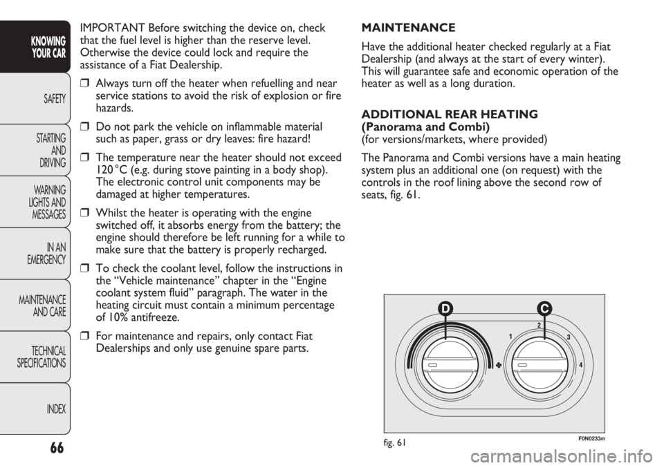
ADDITIONAL REAR HEATING
(Panorama and Combi)
(for versions/markets, where provided)
The Panorama and Combi versions have a main heating
system plus an additional one (on request) with the
controls in the roof lining above the second row of
seats, fig. 61.
Page 71 of 287
67
KNOWING
YOUR CAR
SAFETY
STARTING
AND
DRIVING
WARNING
LIGHTS AND
MESSAGES
IN AN
EMERGENCY
MAINTENANCE
AND CARE
TECHNICAL
SPECIFICATIONS
INDEX
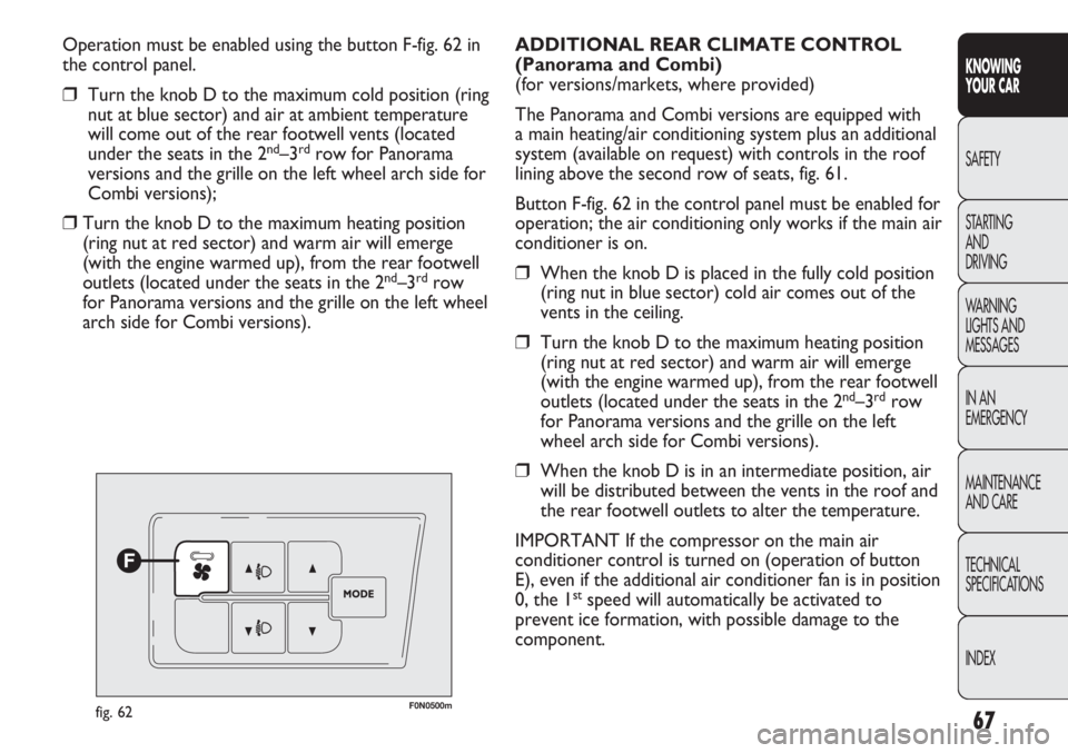
Operation must be enabled using the button F-fig. 62 in
the control panel.
❒Turn the knob D to the maximum cold position (ring
nut at blue sector) and air at ambient temperature
will come out of the rear footwell vents (located
under the seats in the 2
nd–3rdrow for Panorama
versions and the grille on the left wheel arch side for
Combi versions);
❒Turn the knob D to the maximum heating position
(ring nut at red sector) and warm air will emerge
(with the engine warmed up), from the rear footwell
outlets (located under the seats in the 2
nd–3rdrow
for Panorama versions and the grille on the left wheel
arch side for Combi versions).
F0N0500mfig. 62
ADDITIONAL REAR CLIMATE CONTROL
(Panorama and Combi)
(for versions/markets, where provided)
The Panorama and Combi versions are equipped with
a main heating/air conditioning system plus an additional
system (available on request) with controls in the roof
lining above the second row of seats, fig. 61.
Button F-fig. 62 in the control panel must be enabled for
operation; the air conditioning only works if the main air
conditioner is on.
❒When the knob D is placed in the fully cold position
(ring nut in blue sector) cold air comes out of the
vents in the ceiling.
❒Turn the knob D to the maximum heating position
(ring nut at red sector) and warm air will emerge
(with the engine warmed up), from the rear footwell
outlets (located under the seats in the 2
nd–3rdrow
for Panorama versions and the grille on the left
wheel arch side for Combi versions).
❒When the knob D is in an intermediate position, air
will be distributed between the vents in the roof and
the rear footwell outlets to alter the temperature.
IMPORTANT If the compressor on the main air
conditioner control is turned on (operation of button
E), even if the additional air conditioner fan is in position
0, the 1
stspeed will automatically be activated to
prevent ice formation, with possible damage to the
component.
Page 96 of 287
92
KNOWING
YOUR CAR
SAFETY
STARTING
AND
DRIVING
WARNING
LIGHTS AND
MESSAGES
IN AN
EMERGENCY
MAINTENANCE
AND CARE
TECHNICAL
SPECIFICATIONS
INDEX
F0N0217mfig. 105F0N0214mfig. 106
The rear view display is adjusted in mirror mode. When
not in use, it must be closed in the upper oddments
compartment console area.
ACTIVATION
The system is activated with the ignition on and reverse
engaged or by means of a dedicated button. If the
vehicle is in motion, e.g. during a reversing manoeuvre,
the system will operate up to a speed of 15 km/h and go
off when a speed of approximately 18 km/h is exceeded.
When reverse is deactivated, the image will appear on
the display for a further 5 seconds. TV CAMERA SYSTEM
AND REAR VISIBILITY DISPLAY
(for versions/markets where provided)
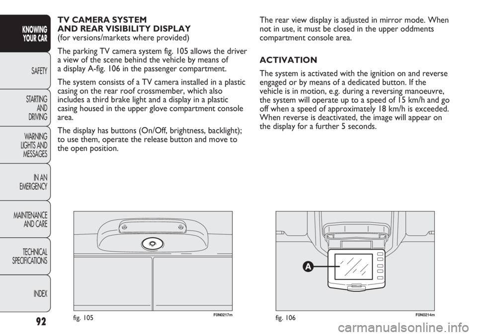
The parking TV camera system fig. 105 allows the driver
a view of the scene behind the vehicle by means of
a display A-fig. 106 in the passenger compartment.
The system consists of a TV camera installed in a plastic
casing on the rear roof crossmember, which also
includes a third brake light and a display in a plastic
casing housed in the upper glove compartment console
area.
The display has buttons (On/Off, brightness, backlight);
to use them, operate the release button and move to
the open position.
Page 110 of 287
106
KNOWING
YOUR CAR
SAFETY
STARTING
AND
DRIVING
WARNING
LIGHTS AND
MESSAGES
IN AN
EMERGENCY
MAINTENANCE
AND CARE
TECHNICAL
SPECIFICATIONS
INDEX
F0N0066mfig. 126F0N0138mfig. 127
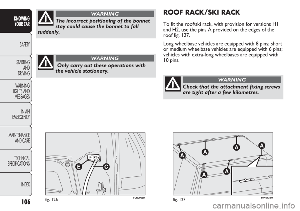
ROOF RACK/SKI RACK
To fit the roof/ski rack, with provision for versions H1
and H2, use the pins A provided on the edges of the
roof fig. 127.
Long wheelbase vehicles are equipped with 8 pins; short
or medium wheelbase vehicles are equipped with 6 pins;
vehicles with extra-long wheelbases are equipped with
10 pins.
Only carry out these operations with
the vehicle stationary.
WARNING
The incorrect positioning of the bonnet
stay could cause the bonnet to fall
suddenly.
WARNING
Check that the attachment fixing screws
are tight after a few kilometres.
WARNING
Page 125 of 287
121
KNOWING
YOUR CAR
SAFETY
STARTING
AND
DRIVING
WARNING
LIGHTS AND
MESSAGES
IN AN
EMERGENCY
MAINTENANCE
AND CARE
TECHNICAL
SPECIFICATIONS
INDEX
RADIO TRANSMITTERS
AND MOBILE PHONES
Radio transmission equipment (e.g.: ETACS mobile
phones, CB radio systems and so on) should not be
used inside the vehicle unless a separate aerial roof-
mounted is fitted.
IMPORTANT The use of similar devices inside the
passenger compartment (without an external aerial)
may, in addition to potential damage to the health of the
passengers, cause malfunctions in the vehicle electronic
systems, compromising the safety of the vehicle.
In addition, transmission and reception of these devices
may be affected by the shielding effect of the vehicle
body.
As far as the use of EC-approved mobile phones is
concerned (GSM, GPRS, UMTS), follow the instructions
for use provided by the mobile phone manufacturer. INSTALLING ELECTRICAL/ELECTRONIC
DEVICES
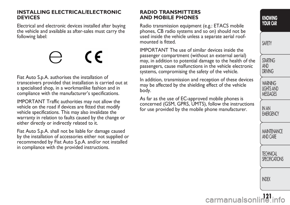
Electrical and electronic devices installed after buying
the vehicle and available as after-sales must carry the
following label:
Fiat Auto S.p.A. authorises the installation of
transceivers provided that installation is carried out at
a specialised shop, in a workmanlike fashion and in
compliance with the manufacturer’s specifications.
IMPORTANT Traffic authorities may not allow the
vehicle on the road if devices are fitted that modify
vehicle specifications. This may also invalidate the
warranty in relation to faults caused by the change or
either directly or indirectly related to it.
Fiat Auto S.p.A. shall not be liable for damage caused
by the installation of accessories either not supplied or
recommended by Fiat Auto S.p.A. and/or not installed
in compliance with the provided instructions.
Page 141 of 287
137
KNOWING
YOUR CAR
SAFETY
STARTING
AND
DRIVING
WARNING
LIGHTS AND
MESSAGES
IN AN
EMERGENCY
MAINTENANCE
AND CARE
TECHNICAL
SPECIFICATIONS
INDEX
The front air bags may not be activated in the following
situations:
❒during collisions against highly deformable objects
that do not affect the vehicle front surface (e.g.
bumper collision against guard rail, heaps of gravel,
etc.);
❒jamming of the vehicle underneath other vehicles or
protective barriers (e.g. underneath a truck or
a guard rail); in this case, the bags would offer no
additional protection with respect to the seat belt
and their deployment is unnecessary. Failure to
deploy in such cases does not consequently indicate
a system fault.
FRONT AIR BAGS
The vehicle is provided with front airbags for the driver
and the passenger.
The front driver/passenger air bags have been designed
to protect the occupants in the event of head-on
crashes of medium-high severity, by placing the cushion
between the occupant and the steering wheel or
dashboard.
Therefore non-activation in other types of collisions
(side collisions, rear shunts, roll-overs, etc.) is not
a system malfunction.
An electronic control unit causes the bag to inflate in
the event of a head-on crash. The bag will inflate
instantaneously placing itself between the front
occupants body and the structures which could cause
injury. It will deflate immediately afterwards.
Driver and passenger front airbags are not
a replacement of but complementary to the belts, which
you are recommended to always wear, as specified by
law in Europe and most non-European countries.
The volume of the front airbags at maximum inflation
fills most of the space between the steering wheel and
the driver and between the dashboard and the
passenger.
In the event of an impact, someone not wearing a seat
belt could move forward and come into contact with
a bag which is still in the opening phase. The protection
offered by the bag is reduced in such a case.
Do not apply stickers or other objects to
the steering wheel, to the passenger’s
side air bag cover or on the roof side lining.
Do not place objects on the passenger side
dashboard because these could interfere with
the correct opening of the airbag (e.g. mobile
phones) and cause severe injury to occupants.
WARNING
The airbags are not deployed in the event of minor
collisions (for which the restraining action of the seat
belts is sufficient). For this reason, the seat belt must be
worn at all times. In the event of side collisions, the seat
belts hold occupants in the correct position and prevent
them being thrown out of the car by a very violent
collision.
Page 144 of 287
140
KNOWING
YOUR CAR
SAFETY
STARTING
AND
DRIVING
WARNING
LIGHTS AND
MESSAGES
IN AN
EMERGENCY
MAINTENANCE
AND CARE
TECHNICAL
SPECIFICATIONS
INDEX
F0N0140mfig. 152F0N0133mfig. 153
IMPORTANT A small amount of dust will be released
when the air bags are deployed. The dust is not harmful
and does not indicate the beginning of a fire.
Furthermore, the surface of the deployed bag and the
interior of the vehicle may be covered in a dusty
residue: this may irritate your skin and eyes. Wash with
mild soap and water in the event of exposure.
The expiration dates of the explosive charge and the
clock wire are shown on a label contained in the glove
box. Contact a Fiat Dealership to have the devices
replaced when the expiry date approaches.
IMPORTANT Should an accident occur in which any of
the safety devices is activated, take the car to a Fiat
Dealership to have the activated devices replaced and to
have the system checked.
Every control, repair and replacement operation
concerning the air bags must only be carried out at
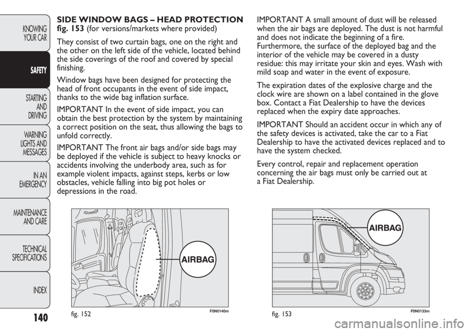
a Fiat Dealership. SIDE WINDOW BAGS – HEAD PROTECTION
fig. 153 (for versions/markets where provided)
They consist of two curtain bags, one on the right and
the other on the left side of the vehicle, located behind
the side coverings of the roof and covered by special
finishing.
Window bags have been designed for protecting the
head of front occupants in the event of side impact,
thanks to the wide bag inflation surface.
IMPORTANT In the event of side impact, you can
obtain the best protection by the system by maintaining
a correct position on the seat, thus allowing the bags to
unfold correctly.
IMPORTANT The front air bags and/or side bags may
be deployed if the vehicle is subject to heavy knocks or
accidents involving the underbody area, such as for
example violent impacts, against steps, kerbs or low
obstacles, vehicle falling into big pot holes or
depressions in the road.
Page 152 of 287
148
KNOWING
YOUR CAR
SAFETY
STARTING
AND
DRIVING
WARNING
LIGHTS AND
MESSAGES
IN AN
EMERGENCY
MAINTENANCE
AND CARE
TECHNICAL
SPECIFICATIONS
INDEX
CONTAINING RUNNING COSTS
Here are some suggestions which may help you to keep
the running costs of your vehicle down and lower the
amount of toxic emissions released into the
atmosphere.
GENERAL CONSIDERATIONS
Vehicle maintenance
Have checks and adjustments carried out in accordance
with the “Scheduled Servicing Plan”.
Tyres
Check the pressure of the tyres routinely at an interval
of no more than 4 weeks: if the pressure is too low,
consumption levels increase as resistance to rolling is
higher.
Unnecessary loads
Do not travel with an overloaded boot. The weight of
the vehicle (especially when driving in town) and its
geometry greatly affect fuel consumption and stability.
Roof rack/ski rack
Remove the roof rack or the ski rack from the roof
after use. These accessories decrease aerodynamic
penetration of the vehicle and have a negative effect on
fuel consumption. It is better to use a trailer, particularly
for transporting bulky objects. In addition to these general precautions, some simple
precautions can improve driving safety, travelling
comfort and vehicle durability:
❒distribute the load evenly over the floor: if it is
necessary to concentrate it in a single area, choose
an area mid-way between both axles;
❒remember that the lower the load, the lower the
vehicle’s centre of gravity, making for a safer drive:
therefore always position the heaviest goods lower
down;
❒lastly, remember that the vehicle’s dynamic
behaviour is affected by the weight transported:
in particular, the stopping distances are longer,
especially at high speed.
If you wish to carry petrol in a reserve
tank, observe the legal restrictions and
only use a tank that is type approved and
properly secured to the load anchorage
eyebolts. However, the risk of fire in the event
of an accident increases.
WARNING
Page 198 of 287
194
KNOWING
YOUR CAR
SAFETY
STARTING
AND
DRIVING
WARNING
LIGHTS AND
MESSAGES
IN AN
EMERGENCY
MAINTENANCE
AND CARE
TECHNICAL
SPECIFICATIONS
INDEX
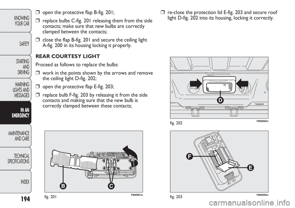
F0N0091mfig. 201
❒open the protective flap B-fig. 201;
❒replace bulbs C-fig. 201 releasing them from the side
contacts; make sure that new bulbs are correctly
clamped between the contacts;
❒close the flap B-fig. 201 and secure the ceiling light
A-fig. 200 in its housing locking it properly.
REAR COURTESY LIGHT
Proceed as follows to replace the bulbs:
❒work in the points shown by the arrows and remove
the ceiling light D-fig. 202;
❒open the protective flap E-fig. 203;
❒replace bulb F-fig. 203 by releasing it from the side
contacts and making sure that the new bulb is
correctly clamped between these contacts;
F0N0093mfig. 203
F0N0092mfig. 202
❒re-close the protection lid E-fig. 203 and secure roof
light D-fig. 202 into its housing, locking it correctly.