fig 36 FIAT DUCATO 244 2005 3.G Manual PDF
[x] Cancel search | Manufacturer: FIAT, Model Year: 2005, Model line: DUCATO 244, Model: FIAT DUCATO 244 2005 3.GPages: 258, PDF Size: 4.05 MB
Page 93 of 258
92GETTING TO KNOW YOUR VEHICLE
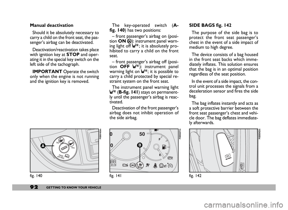
SIDE BAGS fig. 142
The purpose of the side bag is to
protect the front seat passenger’s
chest in the event of a side impact of
medium to high degree.
The device consists of a bag housed
in the front seat backs which imme-
diately inflates. This solution ensures
that the bag is in an optimal position
regardless of the seat position.
In the event of a side impact, the con-
trol unit processes the signals from a
deceleration sensor and fires the side
bag.
The bag inflates instantly and acts as
a soft protective barrier between the
front seat passenger’s chest and vehi-
cle door. The bag deflates immediate-
ly afterwards.
fig. 142
F0D0042m
fig. 140
F0D0163m
Manual deactivation
Should it be absolutely necessary to
carry a child on the front seat, the pas-
senger’s airbag can be deactivated.
Deactivation/reactivation takes place
with ignition key at STOPand oper-
ating it in the special key switch on the
left side of the tachograph.
IMPORTANTOperate the switch
only when the engine is not running
and the ignition key is removed.The key-operated switch (A-
fig. 140) has two positions:
– front passenger’s airbag on (posi-
tion ON
P): instrument panel warn-
ing light off F; it is absolutely pro-
hibited to carry a child on the front
seat.
– front passenger’s airbag off (posi-
tion OFF F): instrument panel
warning light on F; it is possible to
carry a child protected by special re-
straint system on the front seat.
The instrument panel warning light
F(B-fig. 141) stays on permanent-
ly until the passenger’s airbag is reac-
tivated.
Deactivation of the front passenger’s
airbag does not inhibit operation of
the side airbag.
fig. 141
F0D0227m
Page 98 of 258
97GETTING TO KNOW YOUR VEHICLE
SWITCHING THE ASR
SYSTEM ON AND OFF
The ASR function switches on auto-
matically each time the engine is
started.
When travelling the device can be
switched off and on again pressing
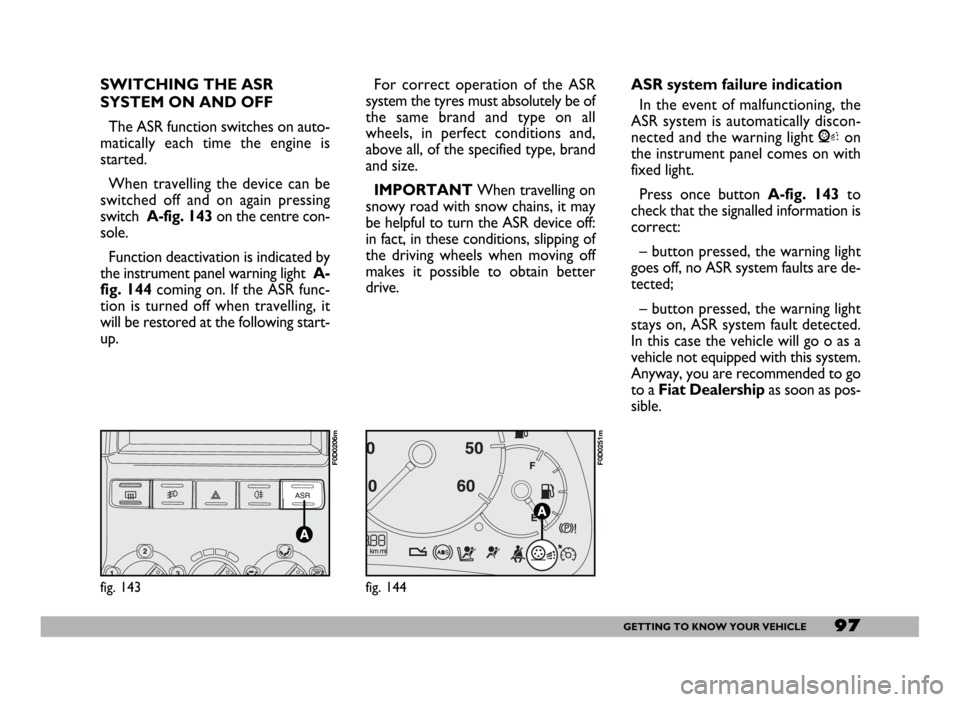
switch A-fig. 143 on the centre con-
sole.
Function deactivation is indicated by
the instrument panel warning light A-
fig. 144coming on. If the ASR func-
tion is turned off when travelling, it
will be restored at the following start-
up.For correct operation of the ASR
system the tyres must absolutely be of
the same brand and type on all
wheels, in perfect conditions and,
above all, of the specified type, brand
and size.
IMPORTANTWhen travelling on
snowy road with snow chains, it may
be helpful to turn the ASR device off:
in fact, in these conditions, slipping of
the driving wheels when moving off
makes it possible to obtain better
drive.
fig. 143
F0D0206m
ASR system failure indication
In the event of malfunctioning, the
ASR system is automatically discon-
nected and the warning light Von
the instrument panel comes on with
fixed light.
Press once button A-fig. 143to
check that the signalled information is
correct:
– button pressed, the warning light
goes off, no ASR system faults are de-
tected;
– button pressed, the warning light
stays on, ASR system fault detected.
In this case the vehicle will go o as a
vehicle not equipped with this system.
Anyway, you are recommended to go
to a Fiat Dealershipas soon as pos-
sible.
fig. 144
F0D0251m
Page 99 of 258
98GETTING TO KNOW YOUR VEHICLE
SOUND SYSTEM
Visit a Fiat Dealership if
you want to fit a sound
system after buying the
vehicle. They can advise you on
how to safeguard battery life. Ex-
cessive idle intake can damage
the battery and may invalidate
the warranty.LIGHT SET-UP
The system consists of:
– radio power supply cables
– dashboard front speaker cables
– housing for the radio
– aerial and relevant wire
HEAVY SET-UP
The system consists of:
– radio power supply cables
– dashboard front speaker cables
– dashboard speakers
– door speaker cables
– door speakers
– housing for the radio
– aerial and relevant wire.
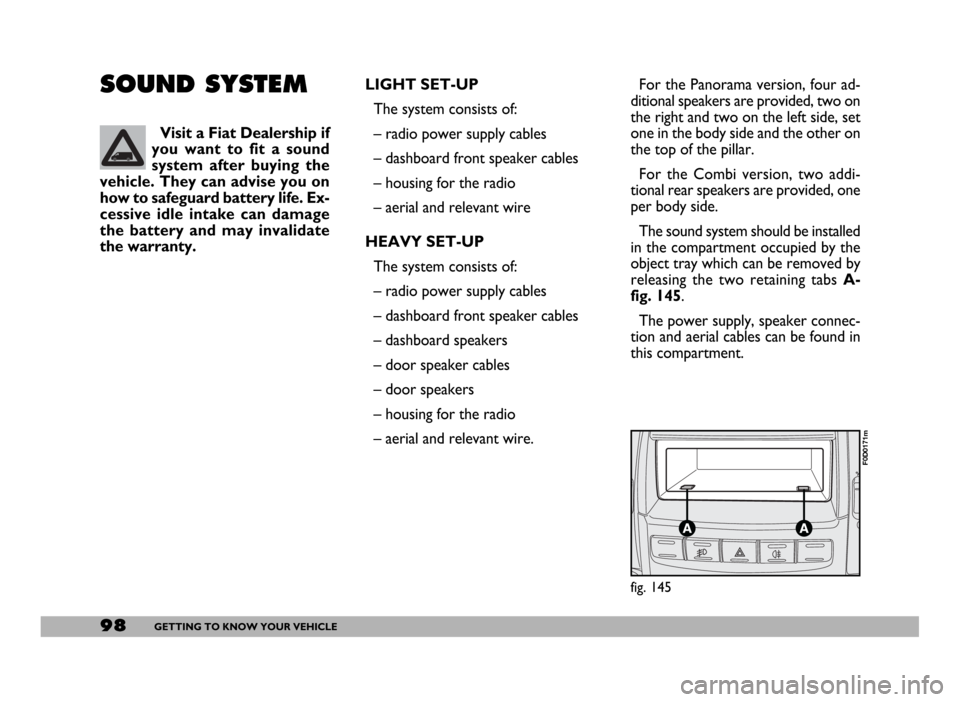
fig. 145
F0D0171m
For the Panorama version, four ad-
ditional speakers are provided, two on
the right and two on the left side, set
one in the body side and the other on
the top of the pillar.
For the Combi version, two addi-
tional rear speakers are provided, one
per body side.
The sound system should be installed
in the compartment occupied by the
object tray which can be removed by
releasing the two retaining tabs A-
fig. 145.
The power supply, speaker connec-
tion and aerial cables can be found in
this compartment.
Page 100 of 258
99GETTING TO KNOW YOUR VEHICLE
IMPORTANT The cables are se-
cured to the heater cables bundle with
adhesive tape to cut out noise.
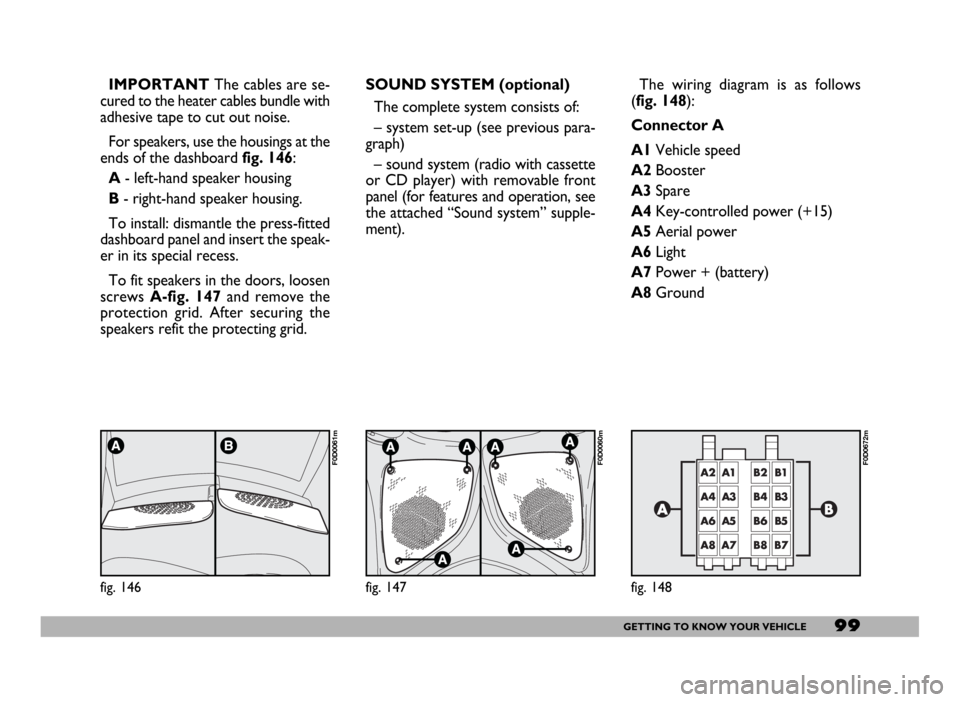
For speakers, use the housings at the
ends of the dashboard fig. 146:
A- left-hand speaker housing
B- right-hand speaker housing.
To install: dismantle the press-fitted
dashboard panel and insert the speak-
er in its special recess.
To fit speakers in the doors, loosen
screws A-fig. 147and remove the
protection grid. After securing the
speakers refit the protecting grid.
fig. 146
F0D0061m
SOUND SYSTEM (optional)
The complete system consists of:
– system set-up (see previous para-
graph)
– sound system (radio with cassette
or CD player) with removable front
panel (for features and operation, see
the attached “Sound system” supple-
ment).
fig. 147
F0D0060m
The wiring diagram is as follows
(fig. 148):
Connector A
A1Vehicle speed
A2Booster
A3Spare
A4Key-controlled power (+15)
A5Aerial power
A6Light
A7Power + (battery)
A8Ground
fig. 148
F0D0672m
Page 101 of 258
100GETTING TO KNOW YOUR VEHICLE
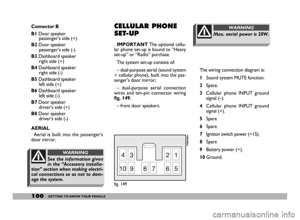
The wiring connection diagram is:
1Sound system MUTE function.
2Spare.
3Cellular phone INPUT ground
signal (–).
4Cellular phone INPUT ground
signal (+).
5Spare
6Spare
7Ignition switch power (+15).
8Spare
9Battery power (+).
10Ground.
Max. aerial power is 20W.
WARNINGConnector B
B1Door speaker
passenger’s side (+)
B2Door speaker
passenger’s side (-)
B3Dashboard speaker
right side (+)
B4Dashboard speaker
right side (-)
B5Dashboard speaker
left side (+)
B6Dashboard speaker
left side (-)
B7Door speaker
driver’s side (+)
B8Door speaker
driver’s side (-)
AERIAL
Aerial is built into the passenger’s
door mirror.CELLULAR PHONE
SET-UP
IMPORTANTThe optional cellu-
lar phone set-up is bound to “Heavy
set-up” or “Radio” purchase.
The system set-up consists of:
– dual-purpose aerial (sound system
+ cellular phone), built into the pas-
senger’s door mirror;
– dual-purpose aerial connection
wires and ten-pin connector wiring
fig. 149;
– front door speakers.
fig. 149
F0D0106m
See the information given
in the “Accessory installa-
tion” section when making electri-
cal connections so as not to dam-
age the system.
WARNING
Page 102 of 258
101GETTING TO KNOW YOUR VEHICLE
RADIO
TRANSMITTERS AND
CELLULAR
TELEPHONES
Cellular telephones and other radio
transceiver equipment (e.g. HAM ra-
dio system) must not be used inside
the vehicle unless a separate aerial is
mounted on the outside of the vehicle.
IMPORTANTThe use of cellular
telephones, HAM transmitters or oth-
er similar devices inside the passenger
compartment (without external aeri-
al) produces RF electromagnetic fields
which, amplified by the resonance ef-
fects inside the passenger compart-
ment may cause vehicle electrical sys-
tem to malfunction.
Moreover, the transmission and re-
ceiving quality deteriorates due to the
screening effect of the vehicle body. Have the cellular phone and the con-
nections to the system installed by a
Fiat Dealership.
The hands-free tele-
phone you purchase will
need to be compatible
with your cellular telephone.
Have the cellular tele-
phone and the connec-
tions to the system in-
stalled by a Fiat Dealership only.
This will ensure the best results
and prevent problems which
could impair vehicle safety.
ROOF RACK/
SKI RACK
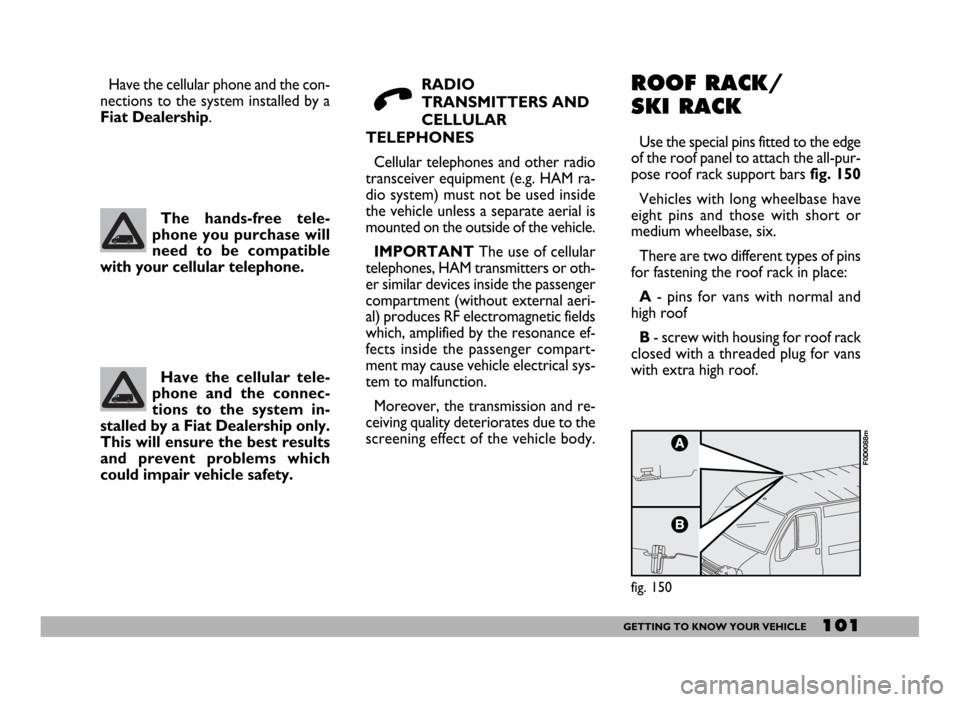
Use the special pins fitted to the edge
of the roof panel to attach the all-pur-
pose roof rack support bars fig. 150
Vehicles with long wheelbase have
eight pins and those with short or
medium wheelbase, six.
There are two different types of pins
for fastening the roof rack in place:
A- pins for vans with normal and
high roof
B- screw with housing for roof rack
closed with a threaded plug for vans
with extra high roof.
fig. 150
F0D0088m
Page 103 of 258
102GETTING TO KNOW YOUR VEHICLE
DIESEL ENGINES
The vehicle must only
be filled with diesel fuel
for motor vehicles, in
compliance with European Spec-
ification EN590. The use of other
products or mixtures may ir-
reparably damage the engine
with invalidation of the warran-
ty due to the damage caused. In
the event of accidentally filling
with another type of fuel, do not
start the engine and empty the
tank. If the engine has been run
even for only a very short time,
in addition to the tank, it is also
necessary to drain out the whole
fuel circuit.AT THE FILLING
STATION
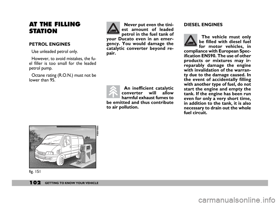
PETROL ENGINES
Use unleaded petrol only.
However, to avoid mistakes, the fu-
el filler is too small for the leaded
petrol pump.
Octane rating (R.O.N.) must not be
lower than 95.
fig. 151
F0D0193m
Never put even the tini-
est amount of leaded
petrol in the fuel tank of
your Ducato even in an emer-
gency. You would damage the
catalytic converter beyond re-
pair.
An inefficient catalytic
converter will allow
harmful exhaust fumes to
be emitted and thus contribute
to air pollution.
Page 104 of 258
103GETTING TO KNOW YOUR VEHICLE
FUEL FILLER CAP
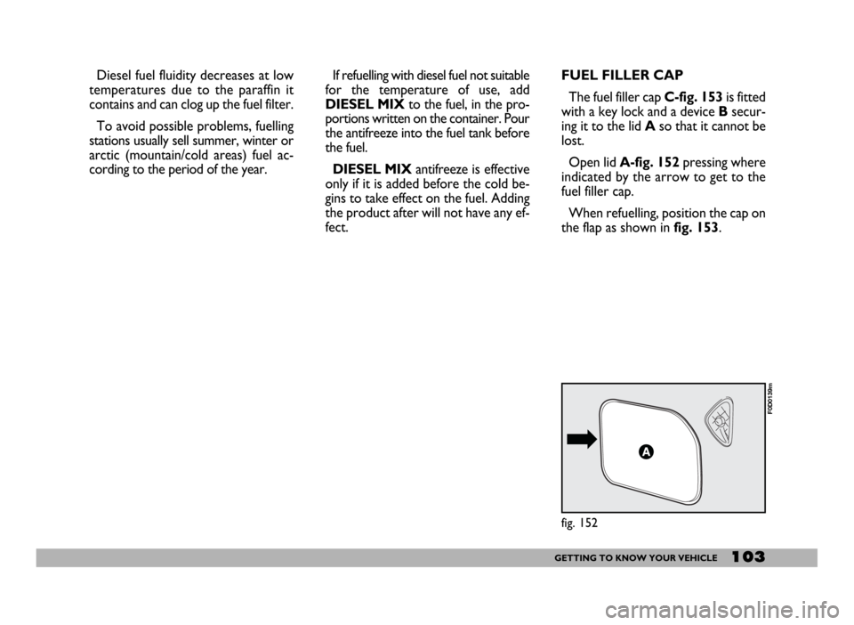
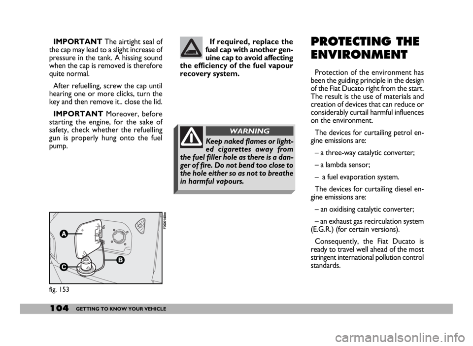
The fuel filler cap C-fig. 153is fitted
with a key lock and a device Bsecur-
ing it to the lid Aso that it cannot be
lost.
Open lid A-fig. 152pressing where
indicated by the arrow to get to the
fuel filler cap.
When refuelling, position the cap on
the flap as shown in fig. 153.
fig. 152
F0D0139m
Diesel fuel fluidity decreases at low
temperatures due to the paraffin it
contains and can clog up the fuel filter.
To avoid possible problems, fuelling
stations usually sell summer, winter or
arctic (mountain/cold areas) fuel ac-
cording to the period of the year. If refuelling with diesel fuel not suitable
for the temperature of use, add
DIESEL MIXto the fuel, in the pro-
portions written on the container. Pour
the antifreeze into the fuel tank before
the fuel.
DIESEL MIXantifreeze is effective
only if it is added before the cold be-
gins to take effect on the fuel. Adding
the product after will not have any ef-
fect.
Page 105 of 258
104GETTING TO KNOW YOUR VEHICLE
IMPORTANTThe airtight seal of
the cap may lead to a slight increase of
pressure in the tank. A hissing sound
when the cap is removed is therefore
quite normal.
After refuelling, screw the cap until
hearing one or more clicks, turn the
key and then remove it.. close the lid.
IMPORTANTMoreover, before
starting the engine, for the sake of
safety, check whether the refuelling
gun is properly hung onto the fuel
pump.If required, replace the
fuel cap with another gen-
uine cap to avoid affecting
the efficiency of the fuel vapour
recovery system.
fig. 153
F0D0140m
PROTECTING THE
ENVIRONMENT
Protection of the environment has
been the guiding principle in the design
of the Fiat Ducato right from the start.
The result is the use of materials and
creation of devices that can reduce or
considerably curtail harmful influences
on the environment.
The devices for curtailing petrol en-
gine emissions are:
– a three-way catalytic converter;
– a lambda sensor;
– a fuel evaporation system.
The devices for curtailing diesel en-
gine emissions are:
– an oxidising catalytic converter;
– an exhaust gas recirculation system
(E.G.R.) (for certain versions).
Consequently, the Fiat Ducato is
ready to travel well ahead of the most
stringent international pollution control
standards.
Keep naked flames or light-
ed cigarettes away from
the fuel filler hole as there is a dan-
ger of fire. Do not bend too close to
the hole either so as not to breathe
in harmful vapours.
WARNING
Page 109 of 258
108GETTING THE BEST OUT OF YOUR VEHICLE
SWITCHING OFF
THE ENGINE
Turn the ignition key to STOPwhile
the engine is idling.
IMPORTANTAfter a taxing drive
you should allow the engine to “catch
its breath” before turning it off by let-
ting it idle to allow temperature in the
engine compartment to fall.PARKING
Switch off the engine, pull up the
handbrake and engage a gear (1st gear
or reverse, according to whether the
vehicle is facing up or downhill) and
leave the wheels turned. If the vehi-
cle is left on a steep slope, wedges or
a rock should be used to lock the
wheels.
Do not leave the ignition key at
MAR to prevent running the battery
down. Always remove the key when
you leave the vehicle.HANDBRAKE
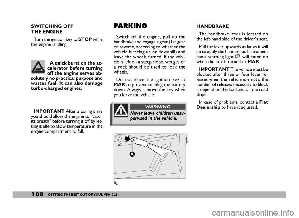
The handbrake lever is located on
the left-hand side of the driver’s seat.
Pull the lever upwards as far as it will
go to apply the handbrake. Instrument
panel warning light xwill come on
when the key is turned to MAR.
IMPORTANTThe vehicle must be
blocked after three or four lever re-
leases when the vehicle is empty; the
number of releases necessary to block
it depend on the load and on the road
slope.
In case of problems, contact a Fiat
Dealershipto have it adjusted. A quick burst on the ac-
celerator before turning
off the engine serves ab-
solutely no practical purpose and
wastes fuel. It can also damage
turbo-charged engines.
fig. 1
F0D0044m
Never leave children unsu-
pervised in the vehicle.
WARNING