FIAT DUCATO BASE CAMPER 2014 Owner handbook (in English)
Manufacturer: FIAT, Model Year: 2014, Model line: DUCATO BASE CAMPER, Model: FIAT DUCATO BASE CAMPER 2014Pages: 367, PDF Size: 20.39 MB
Page 211 of 367
DIPPED HEADLIGHTS
With incandescent bulbs
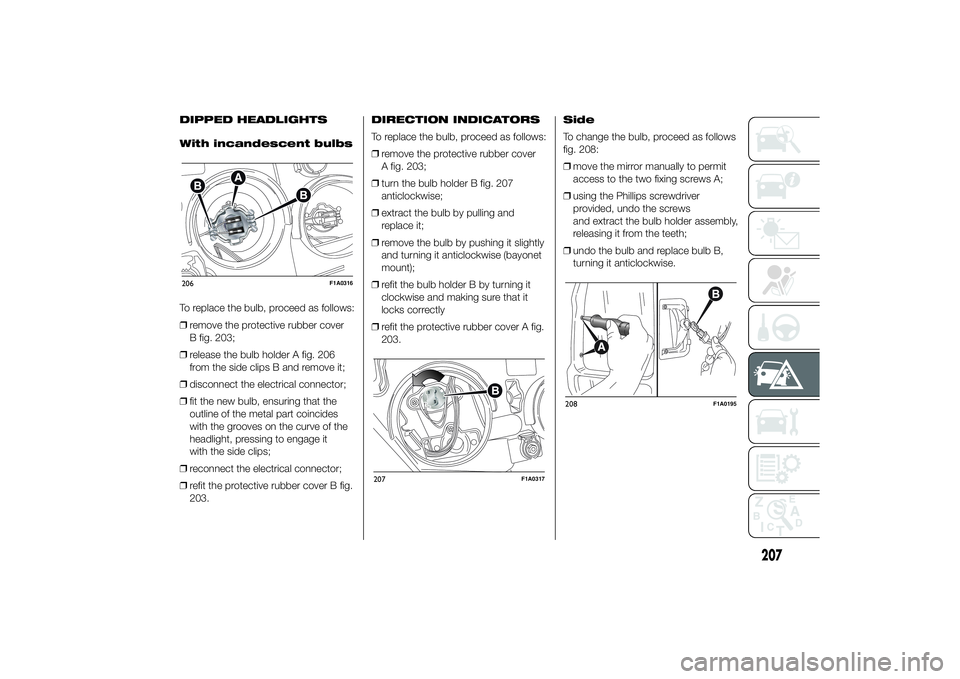
To replace the bulb, proceed as follows:
❒remove the protective rubber cover
B fig. 203;
❒release the bulb holder A fig. 206
from the side clips B and remove it;
❒disconnect the electrical connector;
❒fit the new bulb, ensuring that the
outline of the metal part coincides
with the grooves on the curve of the
headlight, pressing to engage it
with the side clips;
❒reconnect the electrical connector;
❒refit the protective rubber cover B fig.
203.DIRECTION INDICATORS
To replace the bulb, proceed as follows:
❒remove the protective rubber cover
A fig. 203;
❒turn the bulb holder B fig. 207
anticlockwise;
❒extract the bulb by pulling and
replace it;
❒remove the bulb by pushing it slightly
and turning it anticlockwise (bayonet
mount);
❒refit the bulb holder B by turning it
clockwise and making sure that it
locks correctly
❒refit the protective rubber cover A fig.
203.Side
To change the bulb, proceed as follows
fig. 208:
❒move the mirror manually to permit
access to the two fixing screws A;
❒using the Phillips screwdriver
provided, undo the screws
and extract the bulb holder assembly,
releasing it from the teeth;
❒undo the bulb and replace bulb B,
turning it anticlockwise.206
F1A0316
207
F1A0317
208
F1A0195
207
Page 212 of 367
FOG LIGHTS
(for versions/markets, where provided)
To replace the front fog light bulbs,
proceed as follows:
❒steer the wheel completely inwards;
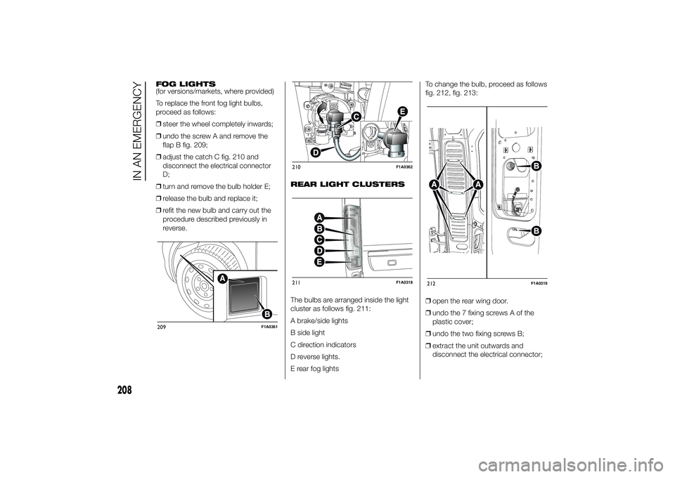
❒undo the screw A and remove the
flap B fig. 209;
❒adjust the catch C fig. 210 and
disconnect the electrical connector
D;
❒turn and remove the bulb holder E;
❒release the bulb and replace it;
❒refit the new bulb and carry out the
procedure described previously in
reverse.REAR LIGHT CLUSTERS
The bulbs are arranged inside the light
cluster as follows fig. 211:
A brake/side lights
B side light
C direction indicators
D reverse lights.
E rear fog lightsTo change the bulb, proceed as follows
fig. 212, fig. 213:
❒open the rear wing door.
❒undo the 7 fixing screws A of the
plastic cover;
❒undo the two fixing screws B;
❒extract the unit outwards and
disconnect the electrical connector;209
F1A0361
210
F1A0362
211
F1A0318
212
F1A0319
208
IN AN EMERGENCY
Page 213 of 367
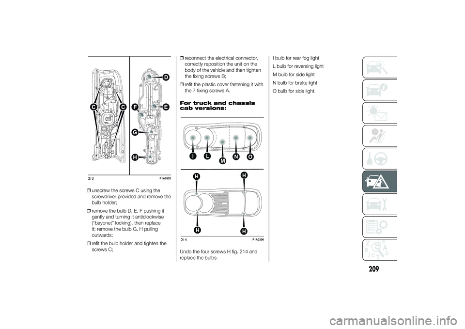
❒unscrew the screws C using the
screwdriver provided and remove the
bulb holder;
❒remove the bulb D, E, F pushing it
gently and turning it anticlockwise
(“bayonet” locking), then replace
it; remove the bulb G, H pulling
outwards;
❒refit the bulb holder and tighten the
screws C;❒reconnect the electrical connector,
correctly reposition the unit on the
body of the vehicle and then tighten
the fixing screws B;
❒refit the plastic cover fastening it with
the 7 fixing screws A.
For truck and chassis
cab versions:
Undo the four screws H fig. 214 and
replace the bulbs:I bulb for rear fog light
L bulb for reversing light
M bulb for side light
N bulb for brake light
O bulb for side light.213
F1A0320
214
F1A0200
209
Page 214 of 367
THIRD BRAKE LIGHTS
To replace the bulb proceed as follows:
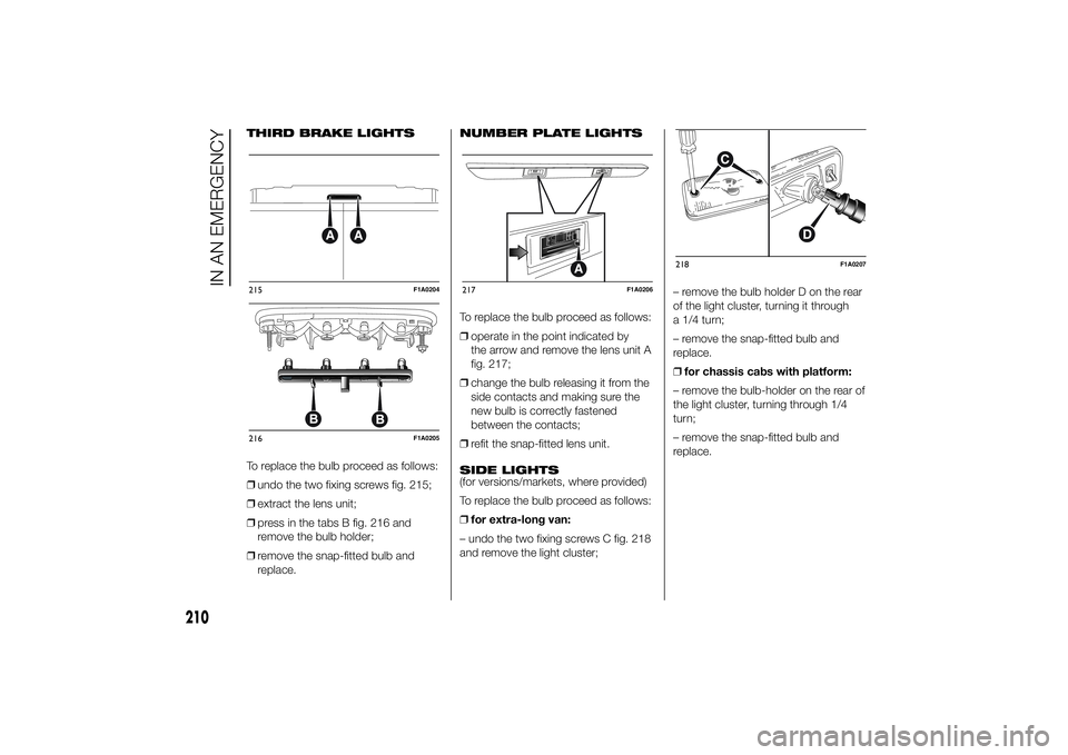
❒undo the two fixing screws fig. 215;
❒extract the lens unit;
❒press in the tabs B fig. 216 and
remove the bulb holder;
❒remove the snap-fitted bulb and
replace.NUMBER PLATE LIGHTS
To replace the bulb proceed as follows:
❒operate in the point indicated by
the arrow and remove the lens unit A
fig. 217;
❒change the bulb releasing it from the
side contacts and making sure the
new bulb is correctly fastened
between the contacts;
❒refit the snap-fitted lens unit.
SIDE LIGHTS
(for versions/markets, where provided)
To replace the bulb proceed as follows:
❒for extra-long van:
– undo the two fixing screws C fig. 218
and remove the light cluster;– remove the bulb holder D on the rear
of the light cluster, turning it through
a 1/4 turn;
– remove the snap-fitted bulb and
replace.
❒for chassis cabs with platform:
– remove the bulb-holder on the rear of
the light cluster, turning through 1/4
turn;
– remove the snap-fitted bulb and
replace.215
F1A0204
216
F1A0205
217
F1A0206
218
F1A0207
210
IN AN EMERGENCY
Page 215 of 367
CHANGING AN
INTERIOR BULBFor the type of bulb and relevant power
rating, see paragraph “Changing a
bulb”.
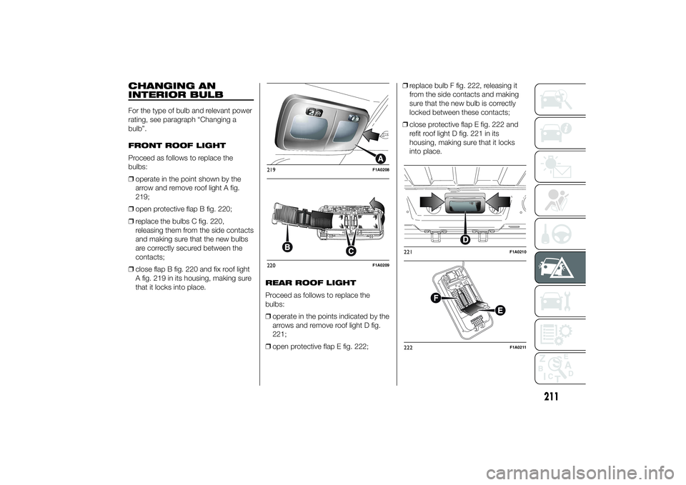
FRONT ROOF LIGHT
Proceed as follows to replace the
bulbs:
❒operate in the point shown by the
arrow and remove roof light A fig.
219;
❒open protective flap B fig. 220;
❒replace the bulbs C fig. 220,
releasing them from the side contacts
and making sure that the new bulbs
are correctly secured between the
contacts;
❒close flap B fig. 220 and fix roof light
A fig. 219 in its housing, making sure
that it locks into place.REAR ROOF LIGHT
Proceed as follows to replace the
bulbs:
❒operate in the points indicated by the
arrows and remove roof light D fig.
221;
❒open protective flap E fig. 222;❒replace bulb F fig. 222, releasing it
from the side contacts and making
sure that the new bulb is correctly
locked between these contacts;
❒close protective flap E fig. 222 and
refit roof light D fig. 221 in its
housing, making sure that it locks
into place.
219
F1A0208
220
F1A0209
221
F1A0210
222
F1A0211
211
Page 216 of 367
REPLACING FUSESGENERAL INFORMATION
45)160) 161) 162) 163)
Fuses protect the electrical system:
they intervene (blow) in the event of a
fault or improper action on the system.
When a device does not work, check
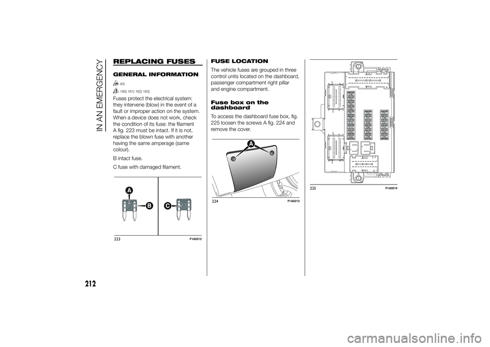
the condition of its fuse: the filament
A fig. 223 must be intact. If it is not,
replace the blown fuse with another
having the same amperage (same
colour).
B intact fuse.
C fuse with damaged filament.FUSE LOCATION
The vehicle fuses are grouped in three
control units located on the dashboard,
passenger compartment right pillar
and engine compartment.
Fuse box on the
dashboard
To access the dashboard fuse box, fig.
225 loosen the screws A fig. 224 and
remove the cover.223
F1A0212
224
F1A0213
225
F1A0214
212
IN AN EMERGENCY
Page 217 of 367
Engine compartment
fuse box
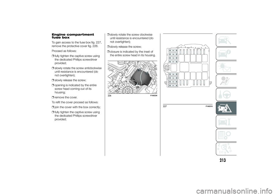
To gain access to the fuse box fig. 227,
remove the protective cover fig. 226.
Proceed as follows:
❒fully tighten the captive screw using
the dedicated Phillips screwdriver
provided;
❒slowly rotate the screw anticlockwise
until resistance is encountered (do
not overtighten);
❒slowly release the screw;
❒opening is indicated by the entire
screw head coming out of its
housing;
❒remove the cover.
To refit the cover proceed as follows:
❒join the cover with the box correctly;
❒fully tighten the captive screw using
the dedicated Phillips screwdriver
provided;❒slowly rotate the screw clockwise
until resistance is encountered (do
not overtighten);
❒slowly release the screw;
❒closure is indicated by the inset of
the entire screw head in its housing.
226
F1A0334
227
F1A0216
213
Page 218 of 367
Right central pillar optional fuse
box
(for versions/markets, where provided)
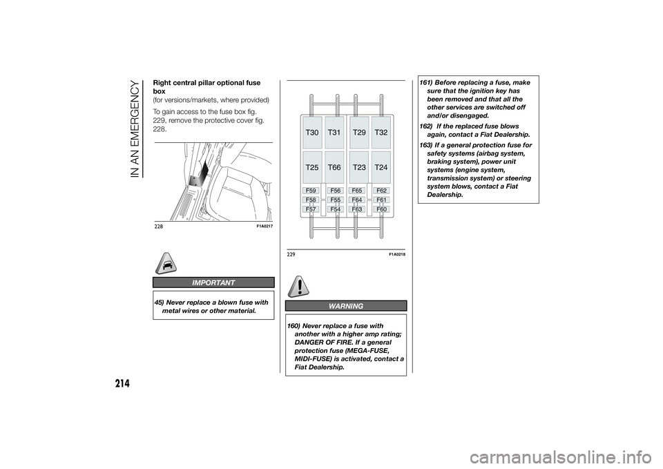
To gain access to the fuse box fig.
229, remove the protective cover fig.
228.
IMPORTANT
45) Never replace a blown fuse with
metal wires or other material.
WARNING
160) Never replace a fuse with
another with a higher amp rating;
DANGER OF FIRE. If a general
protection fuse (MEGA-FUSE,
MIDI-FUSE) is activated, contact a
Fiat Dealership.161) Before replacing a fuse, make
sure that the ignition key has
been removed and that all the
other services are switched off
and/or disengaged.
162) If the replaced fuse blows
again, contact a Fiat Dealership.
163) If a general protection fuse for
safety systems (airbag system,
braking system), power unit
systems (engine system,
transmission system) or steering
system blows, contact a Fiat
Dealership.
228
F1A0217
229
F1A0218
214
IN AN EMERGENCY
Page 219 of 367
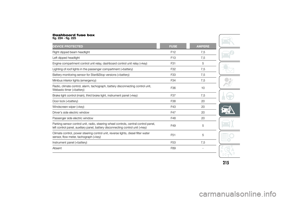
Dashboard fuse box
fig. 224 - fig. 225DEVICE PROTECTED FUSE AMPERERight dipped beam headlight F12 7,5
Left dipped headlight F13 7,5
Engine compartment control unit relay, dashboard control unit relay (+key) F31 5
Lighting of roof lights in the passenger compartment (+battery) F32 7,5
Battery monitoring sensor for Start&Stop versions (+battery) F33 7,5
Minibus interior lights (emergency) F34 7,5
Radio, climate control, alarm, tachograph, battery disconnecting control unit,
Webasto timer (+battery)F36 10
Brake light control (main), third brake light, instrument panel (+key) F37 7,5
Door lock (+battery) F38 20
Windscreen wiper (+key) F43 20
Driver's side electric window F47 20
Passenger side electric window F48 20
Parking sensor control unit, radio, steering wheel controls, central control panel,
left control panel, auxiliary panel, battery disconnecting control unit (+key)F49 5
Climate control, power steering control unit, reverse lights, diesel filter water
sensor, flow meter, tachograph (+key)F51 5
Instrument panel (+battery) F53 7,5
AbsentF89 -
215
Page 220 of 367
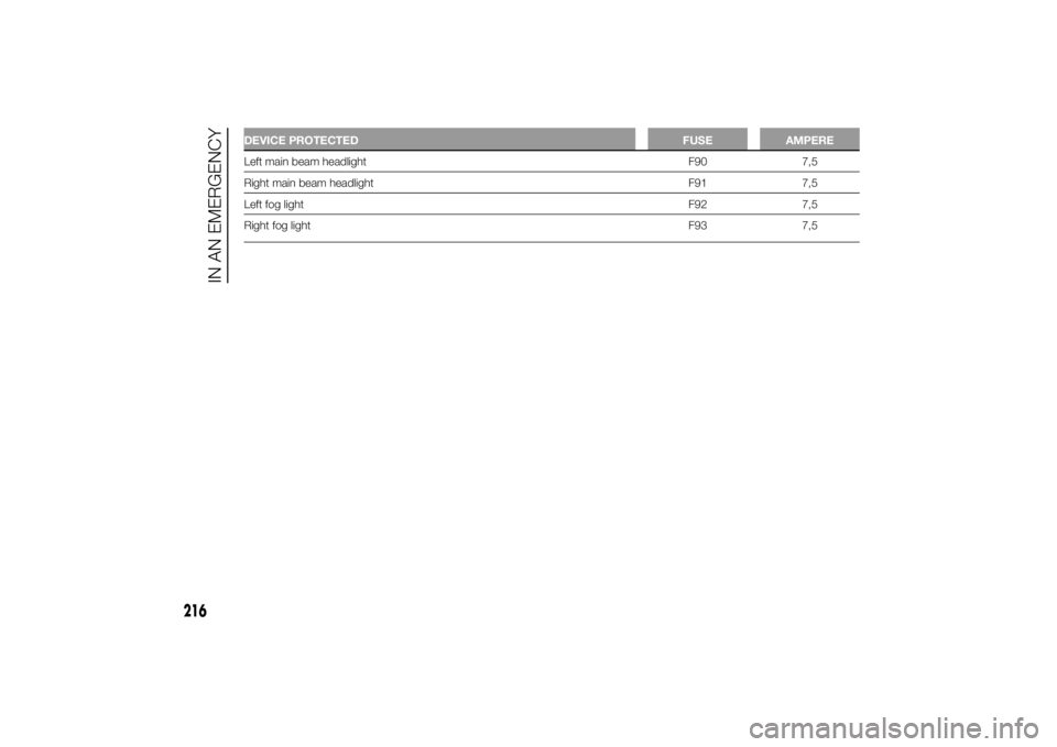
DEVICE PROTECTED FUSE AMPERELeft main beam headlight F90 7,5
Right main beam headlight F91 7,5
Left fog lightF92 7,5
Right fog lightF93 7,5
216
IN AN EMERGENCY