FIAT DUCATO BASE CAMPER 2014 Owner handbook (in English)
Manufacturer: FIAT, Model Year: 2014, Model line: DUCATO BASE CAMPER, Model: FIAT DUCATO BASE CAMPER 2014Pages: 367, PDF Size: 20.39 MB
Page 221 of 367
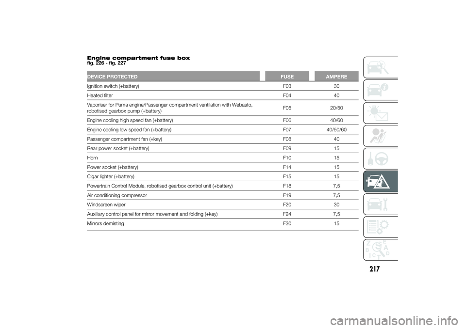
Engine compartment fuse box
fig. 226 - fig. 227DEVICE PROTECTED FUSE AMPEREIgnition switch (+battery) F03 30
Heated filterF04 40
Vaporiser for Puma engine/Passenger compartment ventilation with Webasto,
robotised gearbox pump (+battery)F05 20/50
Engine cooling high speed fan (+battery) F06 40/60
Engine cooling low speed fan (+battery) F07 40/50/60
Passenger compartment fan (+key) F08 40
Rear power socket (+battery) F09 15
HornF10 15
Power socket (+battery) F14 15
Cigar lighter (+battery) F15 15
Powertrain Control Module, robotised gearbox control unit (+battery) F18 7,5
Air conditioning compressor F19 7,5
Windscreen wiper F20 30
Auxiliary control panel for mirror movement and folding (+key) F24 7,5
Mirrors demisting F30 15
217
Page 222 of 367
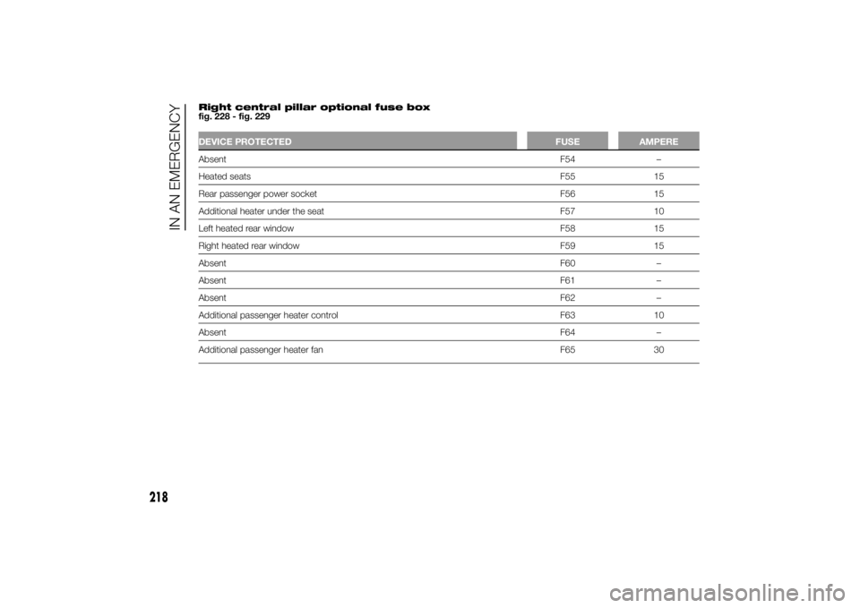
Right central pillar optional fuse box
fig. 228 - fig. 229DEVICE PROTECTED FUSE AMPEREAbsentF54 –
Heated seatsF55 15
Rear passenger power socket F56 15
Additional heater under the seat F57 10
Left heated rear window F58 15
Right heated rear window F59 15
AbsentF60 –
AbsentF61 –
AbsentF62 –
Additional passenger heater control F63 10
AbsentF64 –
Additional passenger heater fan F65 30
218
IN AN EMERGENCY
Page 223 of 367
BATTERY
RECHARGINGIMPORTANT The battery recharging
procedure is given as information only.
You are advised to contact a Fiat
Dealership to have this operation
carried out.
IMPORTANT After turning the ignition
key to STOP and having closed the
driver side door, wait at least one
minute before disconnecting the
electrical supply from the battery. When
reconnecting the electrical supply to
the battery, make sure that the ignition
key is in the STOP position and the
driver side door is closed.
Charging should be slow at a low
ampere rating for approximately 24
hours. Charging for a longer time may
damage the battery.
164) 165)
IN THE ABSENCE OF
START&STOP SYSTEM
To recharge, proceed as follows:
❒disconnect the negative battery
terminal;
❒connect the charger cables to the
battery terminals, observing the
polarity;❒turn on the charger;
❒when it is recharged, turn the charger
off before disconnecting it from the
battery;
❒reconnect the negative battery
terminal.
WITH START&STOP
SYSTEM
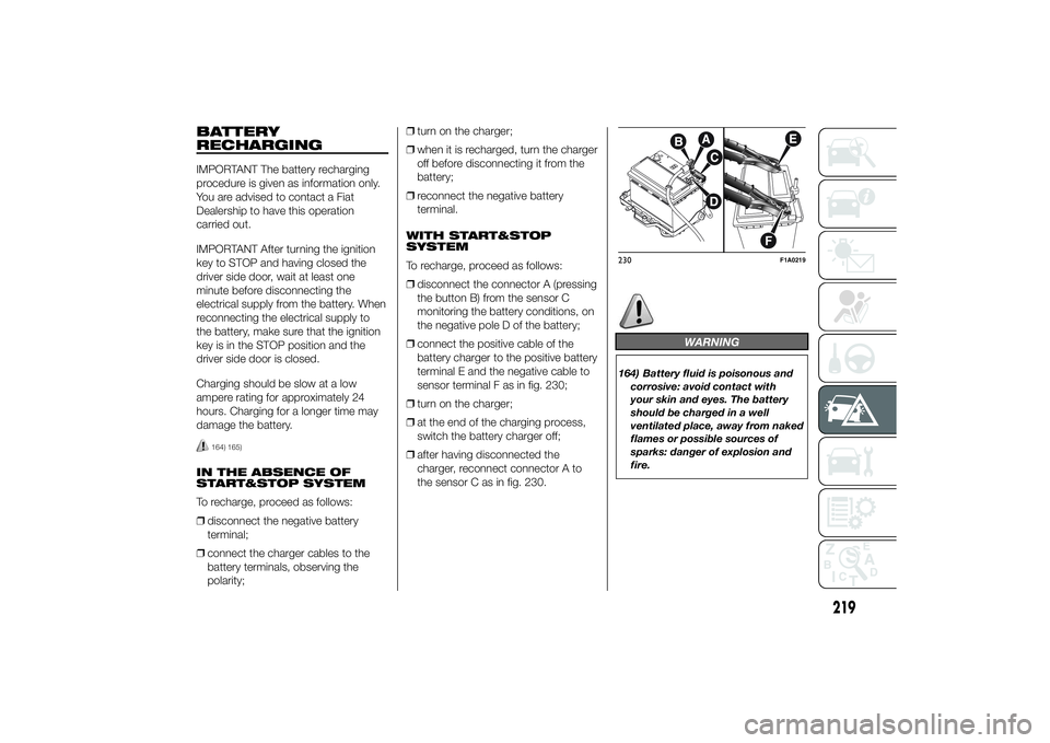
To recharge, proceed as follows:
❒disconnect the connector A (pressing
the button B) from the sensor C
monitoring the battery conditions, on
the negative pole D of the battery;
❒connect the positive cable of the
battery charger to the positive battery
terminal E and the negative cable to
sensor terminal F as in fig. 230;
❒turn on the charger;
❒at the end of the charging process,
switch the battery charger off;
❒after having disconnected the
charger, reconnect connector A to
the sensor C as in fig. 230.
WARNING
164) Battery fluid is poisonous and
corrosive: avoid contact with
your skin and eyes. The battery
should be charged in a well
ventilated place, away from naked
flames or possible sources of
sparks: danger of explosion and
fire.230
F1A0219
219
Page 224 of 367
165) Do not attempt to charge a
frozen battery: it must be thawed
first, otherwise it may explode.
If freezing has occurred, the
battery should be checked by
skilled personnel to make sure
that the internal elements are not
damaged and that the body is
not cracked, with the risk of
leaking poisonous and corrosive
acid.
LIFTING THE
VEHICLEIf the vehicle needs to be lifted, go to a
Fiat Dealership which is equipped
with the arm hoist or workshop lift.
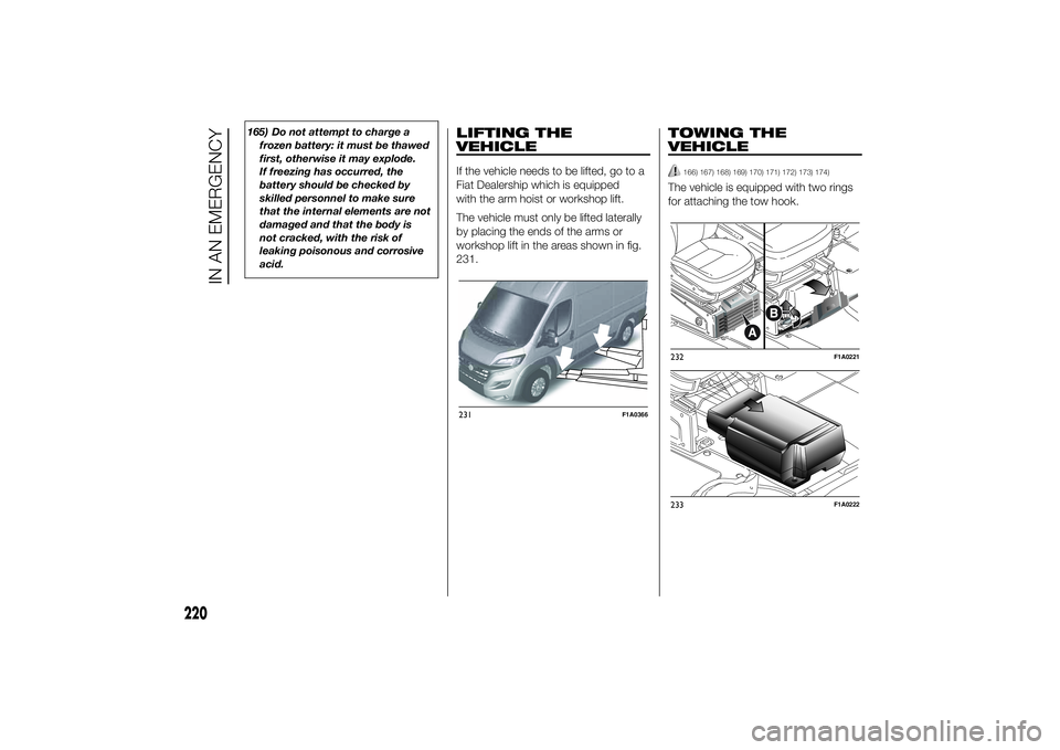
The vehicle must only be lifted laterally
by placing the ends of the arms or
workshop lift in the areas shown in fig.
231.
TOWING THE
VEHICLE
166) 167) 168) 169) 170) 171) 172) 173) 174)
The vehicle is equipped with two rings
for attaching the tow hook.
231
F1A0366
232
F1A0221
233
F1A0222
220
IN AN EMERGENCY
Page 225 of 367
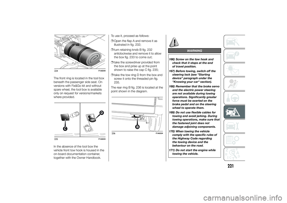
The front ring is located in the tool box
beneath the passenger side seat. On
versions with Fix&Go kit and without
spare wheel, the tool box is available
only on request for versions/markets
where provided.
In the absence of the tool box the
vehicle front tow hook is housed in the
on-board documentation container,
together with the Owner Handbook.To use it, proceed as follows:
❒Open the flap A and remove it as
illustrated in fig. 232;
❒turn retaining knob B fig. 232
anticlockwise and remove it to allow
the box fig. 233 to come out;
❒take the screwdriver provided from
the box and prise up at the point
shown to raise the cap C fig. 235;
❒take the tow ring D from the box and
screw it onto the threaded pin fig.
235.
The rear ring B fig. 236 is located at the
point shown in the diagram.
WARNING
166) Screw on the tow hook and
check that it stops at the end
of travel position.
167) Before towing, switch off the
steering lock (see "Starting
device" paragraph under the
"Knowing your car" section).
168) Remember that the brake servo
and the electric power steering
are not available during towing
operations. Significantly greater
force must be exerted on the
brake pedal and on the steering
wheel to operate them.
169) Do not use flexible cables for
towing and avoid jerking. During
towing operations, make sure that
the fastened joint does not
damage adjoining components.
170) When towing the vehicle
comply with the specific rules of
the Highway Code regarding
the towing device and the
behaviour on the road.
171) Do not start the engine while
towing the vehicle.
234
F1A0344
235
F1A0223
236
F1A0224
221
Page 226 of 367
172) Towing must be made
exclusively on roads/streets; the
device must not be used to
recover the vehicle if it got off the
road.
173) Towing must not be made for
getting past significant obstacles
on the road (e.g. heaps of snow
or material on the road surface).
174) Towing must take place with
the two vehicles (one towing,
the other towed) aligned as much
as possible; towing by roadside
assistance vehicles, too, must
take place with the two vehicles
aligned as much as possible
222
IN AN EMERGENCY
Page 227 of 367
SERVICING AND MAINTENANCE
Correct maintenance permits the
performance of the car to be
maintained over time, as well as limited
running costs and safeguarding the
efficiency of the safety systems.
This chapter explains how.SCHEDULED SERVICING ...............224
SCHEDULED SERVICING PLAN .....225
PERIODIC CHECKS ........................228
DEMANDING VEHICLE USE ...........228
CHECKING LEVELS........................229
AIR CLEANER/POLLEN FILTER ......236
BATTERY ........................................237
WHEELS AND TYRES.....................240
RUBBER HOSES ............................241
WINDSCREEN WIPER ....................241
BODYWORK ...................................243
INTERIORS .....................................246
223
Page 228 of 367
SCHEDULED
SERVICINGCorrect servicing is essential for
ensuring long vehicle life under the best
conditions.
This is why Fiat has planned a series of
checks and maintenance operations
every 48,000 km depending on the
engine version.
The scheduled maintenance does not,
however, cover all the needs of the
vehicle: also during the initial period,
before the 48,000 km service and
between one service and the next,
ordinary care such as systematic fluid
level checks with top ups and tyre
pressure checks, etc. remain
necessary.
IMPORTANT The Scheduled Servicing
services are set out by the
Manufacturer. Failure to have them
carried out may invalidate the warranty.
Scheduled Servicing can be carried
out by any Fiat Dealership, at
pre-established times.
If during each operation, in addition to
the ones scheduled, the need arises for
further replacements or repairs, these
may only be carried out with the
express agreement of the Customer.IMPORTANT It is advisable to inform a
Fiat Dealership of any small operating
irregularities without waiting for the next
service.
If your vehicle is used frequently for
towing, the interval between service
coupons must be reduced.
224
SERVICING AND MAINTENANCE
Page 229 of 367
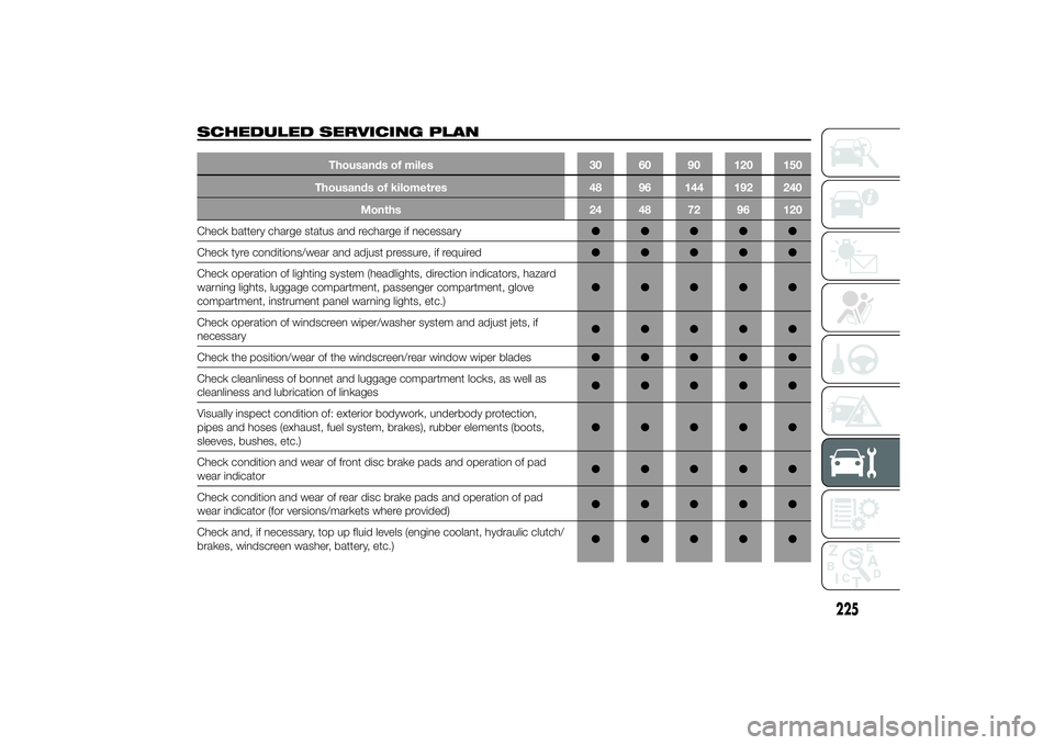
SCHEDULED SERVICING PLAN
Thousands of miles 30 60 90 120 150
Thousands of kilometres 48 96 144 192 240
Months 24 48 72 96 120
Check battery charge status and recharge if necessary●●●●●
Check tyre conditions/wear and adjust pressure, if required●●●●●
Check operation of lighting system (headlights, direction indicators, hazard
warning lights, luggage compartment, passenger compartment, glove
compartment, instrument panel warning lights, etc.)●●●●●
Check operation of windscreen wiper/washer system and adjust jets, if
necessary●●●●●
Check the position/wear of the windscreen/rear window wiper blades●●●●●
Check cleanliness of bonnet and luggage compartment locks, as well as
cleanliness and lubrication of linkages●●●●●
Visually inspect condition of: exterior bodywork, underbody protection,
pipes and hoses (exhaust, fuel system, brakes), rubber elements (boots,
sleeves, bushes, etc.)●●●●●
Check condition and wear of front disc brake pads and operation of pad
wear indicator●●●●●
Check condition and wear of rear disc brake pads and operation of pad
wear indicator (for versions/markets where provided)●●●●●
Check and, if necessary, top up fluid levels (engine coolant, hydraulic clutch/
brakes, windscreen washer, battery, etc.)●●●●●
225
Page 230 of 367
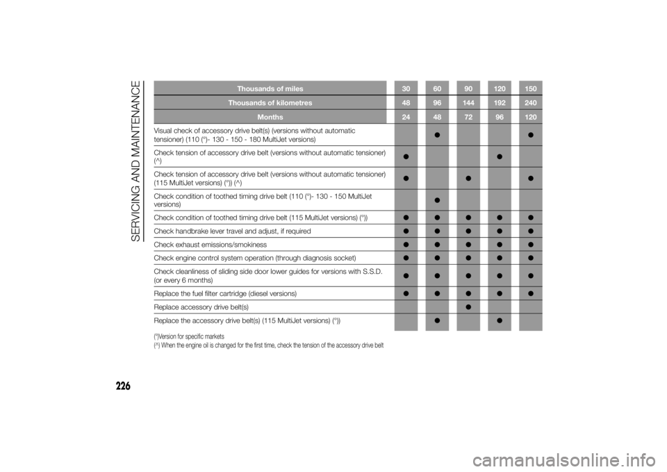
Thousands of miles 30 60 90 120 150
Thousands of kilometres 48 96 144 192 240
Months 24 48 72 96 120
Visual check of accessory drive belt(s) (versions without automatic
tensioner) (110 (°)- 130 - 150 - 180 MultiJet versions)●●
Check tension of accessory drive belt (versions without automatic tensioner)
(^)●●
Check tension of accessory drive belt (versions without automatic tensioner)
(115 MultiJet versions) (°)) (^)●●●
Check condition of toothed timing drive belt (110 (°)- 130 - 150 MultiJet
versions)●
Check condition of toothed timing drive belt (115 MultiJet versions) (°))●●●●●
Check handbrake lever travel and adjust, if required●●●●●
Check exhaust emissions/smokiness●●●●●
Check engine control system operation (through diagnosis socket)●●●●●
Check cleanliness of sliding side door lower guides for versions with S.S.D.
(or every 6 months)●●●●●
Replace the fuel filter cartridge (diesel versions)●●●●●
Replace accessory drive belt(s)●
Replace the accessory drive belt(s) (115 MultiJet versions) (°))●●(°)Version for specific markets
(^) When the engine oil is changed for the first time, check the tension of the accessory drive belt
226
SERVICING AND MAINTENANCE