display FIAT DUCATO BASE CAMPER 2014 Owner handbook (in English)
[x] Cancel search | Manufacturer: FIAT, Model Year: 2014, Model line: DUCATO BASE CAMPER, Model: FIAT DUCATO BASE CAMPER 2014Pages: 367, PDF Size: 20.39 MB
Page 96 of 367
14) Always use genuine spare parts
when replacing the bulbs of the
headlights. Other bulbs may
reduce the system performance.
15) Clean the windscreen from
foreign matters such as bird
droppings, insects, snow or ice.
EOBD SYSTEMThe EOBD system (European On Board
Diagnosis) allows continuous diagnosis
of emission-related components on
the vehicle to be made.
It also alerts the driver, by turning on
the
warning light in the instrument
panel (together with relevant message
in the multifunction display, for
versions/markets where provided) when
these components are no longer in
peak condition (see “Warning lights and
messages” paragraph).
The aim of the system is to:
❒monitor system efficiency;
❒indicate an increase in emissions due
to vehicle malfunction;
❒indicate the need to replace
components which have
deteriorated.
The system also has a connector that
can be interfaced with appropriate
equipment, which makes it possible to
read the error codes stored in the
control unit together with a series of
specific parameters for engine
operation and diagnosis. This check
can also be carried out by traffic control
authorities.IMPORTANT After eliminating the
failure, to check the system completely,
Fiat Dealerships run a bench test and,
if necessary, road tests which may
also call for a long journey.
92
KNOW YOUR VEHICLE
Page 97 of 367
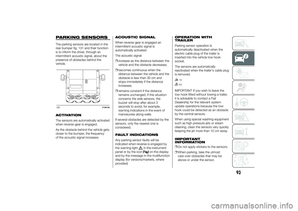
PARKING SENSORSThe parking sensors are located in the
rear bumper fig. 131 and their function
is to inform the driver, through an
intermittent acoustic signal, about the
presence of obstacles behind the
vehicle.
ACTIVATION
The sensors are automatically activated
when reverse gear is engaged.
As the obstacle behind the vehicle gets
closer to the bumper, the frequency
of the acoustic signal increases.ACOUSTIC SIGNAL
When reverse gear is engaged an
intermittent acoustic signal is
automatically activated.
The acoustic signal:
❒increase as the distance between the
vehicle and the obstacle decreases;
❒becomes continuous when the
distance between the vehicle and the
obstacle is less than 30 cm and
stops immediately if the distance
increases;
❒remains constant if the distance
remains unchanged; if this situation
concerns the side sensors, the
buzzer will stop after about 3
seconds to avoid, for example,
warning indications in the event of
manoeuvres along walls.
If several obstacles are detected by the
sensors, only the nearest one is
considered.
FAULT INDICATIONS
Any parking sensor faults will be
indicated when reverse is engaged by
the warning light
in the instrument
panel or by the icon
on the display
and by the message in the multifunction
display (for versions/markets, where
provided)OPERATION WITH
TRAILER
Parking sensor operation is
automatically deactivated when the
electric cable plug of the trailer is
inserted into the vehicle tow hook
socket.
The sensors are automatically
reactivated when the trailer's cable plug
is removed.
16)82)
IMPORTANT If you wish to leave the
tow hook fitted without towing a trailer,
it is advisable to contact a Fiat
Dealership for the relevant system
update operations because the tow
hook could be detected as an obstacle
by the central sensors.
When using special washing equipment
such as high pressure jets or steam
cleaning, clean the sensors very quickly
keeping the jet more than 10 cm away.
IMPORTANT
INFORMATION
❒Do not apply stickers to the sensors.
❒When parking, take the utmost
care over obstacles that may be
above or under the sensor.
131
F1A0134
93
Page 99 of 367
START&STOP
SYSTEM
IN BRIEF
The Start&Stop device automatically
stops the engine each time the
vehicle is stationary and starts it
again when the driver wants to move
off. This improves the efficiency of
the vehicle by reducing fuel
consumption, the emission of harmful
gases and noise pollution.
OPERATING MODES
Engine stopping mode
WITH MANUAL GEARBOX
With the vehicle stationary, the engine
stops with the gearbox in neutral and
the clutch pedal released.
NoteThe engine can only be stopped
automatically after exceeding a speed
of about 10 km/h, to prevent the engine
from being repeatedly stopped when
driving at walking pace.
Engine stopping is signalled by theicon on the display.Engine restarting mode
WITH MANUAL GEARBOX
Depress the clutch pedal to restart the
engine.
MANUAL ACTIVATION
AND DEACTIVATION OF
THE SYSTEM
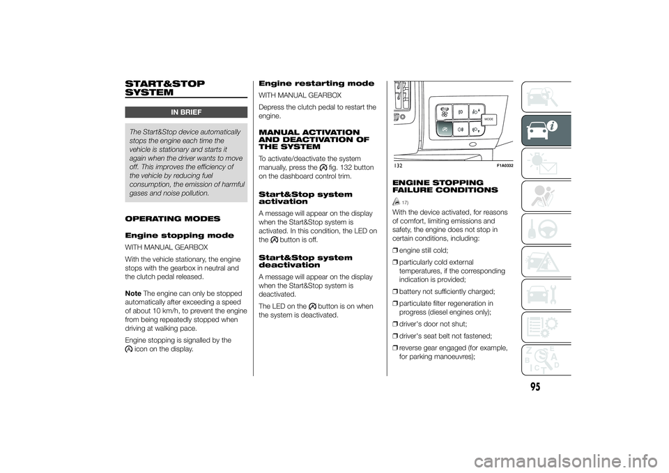
To activate/deactivate the system
manually, press the
fig. 132 button
on the dashboard control trim.
Start&Stop system
activation
A message will appear on the display
when the Start&Stop system is
activated. In this condition, the LED on
the
button is off.
Start&Stop system
deactivation
A message will appear on the display
when the Start&Stop system is
deactivated.
The LED on the
button is on when
the system is deactivated.ENGINE STOPPING
FAILURE CONDITIONS
17)
With the device activated, for reasons
of comfort, limiting emissions and
safety, the engine does not stop in
certain conditions, including:
❒engine still cold;
❒particularly cold external
temperatures, if the corresponding
indication is provided;
❒battery not sufficiently charged;
❒particulate filter regeneration in
progress (diesel engines only);
❒driver's door not shut;
❒driver's seat belt not fastened;
❒reverse gear engaged (for example,
for parking manoeuvres);
MODEMODE
132
F1A0332
95
Page 100 of 367
❒automatic climate control, if a
suitable thermal comfort level has not
yet been reached or MAX-DEF
function activation;
❒during the first period of use, to
initialise the system;
❒if the Hill Descent Control system is
active.
RESTARTING
CONDITIONS
For reasons of comfort, limiting harmful
emissions and safety purposes, the
power unit can restart automatically
without any action by the driver if
certain conditions are met, including:
❒battery not sufficiently charged;
❒reduced braking system vacuum
(e.g. if the brake pedal is pressed
repeatedly);
❒vehicle in motion (e.g. when driving
on roads with a gradient);
❒stopping the engine through the
Start&Stop system for more than
about three minutes.
❒automatic climate control system for
adjusting the thermal comfort level or
to enable MAX-DEF function.
With a gear engaged, the engine can
be automatically restarted only by
fully depressing the clutch pedal.NoteIf the engine stops and this is not
desired, due for example to the clutch
pedal being released sharply with a
gear engaged, if the Start&Stop system
is active, the engine can be restarted
by fully depressing the clutch pedal
or by placing the gear lever in neutral.
NoteIf the clutch is not pressed, when
approx. three minutes have elapsed
since the engine was stopped, the
engine can only be restarted using the
key.
SAFETY FUNCTIONS
In engine cut-out conditions through
the Start&Stop system, if the driver
unfastens his/her seat belt and opens
the driver's door or the passenger door,
the engine can be restarted only by
using the key. The driver is notified of
this condition by a buzzer, through the
warning light flashing in the
instrument panel and, where provided,
by a message in the display."ENERGY SAVING"
FUNCTION
(for versions/markets, where provided)
If, after the engine has been
automatically restarted, the driver does
not take any action for a period of
about 3 minutes, the Start&Stop
system will definitively stop the engine
to avoid fuel consumption. The engine
can only be started using the key in
such cases.
NoteIn any case, it is possible to keep
the engine running by deactivating
the Start&Stop system.
IRREGULAR OPERATION
In the event of malfunction, the
Start&Stop system is deactivated. The
driver is informed about the fault
through the switching on of the
icon
together with a message on the
display. In this case, contact a Fiat
Dealership.
96
KNOW YOUR VEHICLE
Page 106 of 367
The diesel particulate filter has been
adopted to eliminate almost all
particulates in compliance with current /
future legal regulations.
During normal use of the vehicle, the
Powertrain Control Module records
a set of data (travel time, type of route,
temperatures reached etc.) and
calculates how much particulate has
been trapped by the filter.
Since this filter physically traps
particulate, it should be regenerated
(cleaned) at regular intervals by burning
carbon particles.
The regeneration procedure is
controlled automatically by the
Powertrain Control Module according
to the filter conditions and vehicle
usage conditions.
During regeneration, the following may
occur: a limited increase in the engine
speed, activation of the fan, a limited
increase in fumes and high
temperatures at the exhaust.
These are not faults; they do not impair
vehicle performance or damage the
environment. If the dedicated message
is displayed, refer to paragraph
"Warning lights and messages".
WARNING
89) The diesel particulate filter (DPF)
reaches high temperatures during
normal operation. Do not park
the vehicle on flammable material
(grass, dry leaves, pine needles
etc.): fire hazard.
102
KNOW YOUR VEHICLE
Page 107 of 367
KNOWING THE INSTRUMENT PANEL
This section of the booklet gives you all
the information you need to
understand, interpret and use the
instrument panel correctly.CONTROL PANEL AND
INSTRUMENTS ...............................104
DISPLAY ........................................109
TRIP COMPUTER ...........................118
WARNING LIGHTS AND
MESSAGES ....................................121
- LOW BRAKE FLUID/HANDBRAKE
ENGAGED .......................................... 121
- EBD FAILURE .................................. 122
- AIRBAG FAILURE ............................. 122
- SEAT BELTS NOT FASTENED .......... 123
- ENGINE COOLANT TEMPERATURE
TOO HIGH .......................................... 124
- LOW BATTERY CHARGE ................. 124
- LOW ENGINE OIL PRESSURE ......... 125
-ENGINE OIL DETERIORATED ........... 125
-INCOMPLETE DOOR/LOAD
COMPARTMENT CLOSURE ............... 126
- POWER STEERING FAILURE ........... 126
-SELF-LEVELLING SUSPENSION
FAILURE ............................................. 126
- INJECTION/EOBD SYSTEM
FAILURE ............................................. 128
- ABS FAILURE ................................... 129
-FUEL RESERVE ................................ 129
- GLOW PLUG HEATING/GLOW
PLUG HEATING FAILURE ................... 130
- WATER IN DIESEL FILTER ................ 130
-VEHICLE PROTECTION SYSTEM
FAILURE - FIAT CODE ........................ 131
- REAR FOG LIGHTS .......................... 131
-GENERIC FAILURE INDICATION ....... 131
-DPF (PARTICULATE FILTER)
CLEANING UNDERWAY ..................... 133
-WORN BRAKE PADS ........................ 134
-DRIVING ADVISOR ........................... 135
- TPMS ............................................... 136
- DIPPED HEADLIGHTS ..................... 137- FOLLOW ME HOME ........................ 137
- LEFT-HAND DIRECTION INDICATOR
............................................................ 137
- RIGHT-HAND DIRECTION
INDICATOR ........................................ 138
-FOG LIGHTS ..................................... 138
- CRUISE CONTROL .......................... 138
-SPEED LIMITER ................................ 138
- AUTOMATIC MAIN BEAM
HEADLIGHTS ..................................... 139
- MAIN BEAM HEADLIGHTS .............. 139
-EXTERIOR LIGHTS FAULT ................ 140
-BRAKE LIGHT FAILURE .................... 140
-MAIN BEAM AUTOMATISM FAULT ... 141
-POSSIBLE ICE ON ROAD ................. 141
-SPEED LIMIT EXCEEDED ................. 141
-SCHEDULED SERVICING ................. 141
-DRIVING ADVISOR SYSTEM
FAILURE ............................................. 142
-TRAFFIC SIGN RECOGNITION
FAILURE ............................................. 142
-LIMITED RANGE ............................... 142
-START&STOP SYSTEM
ACTIVATION/DEACTIVATION .............. 143
-START&STOP FAILURE .................... 143
103
Page 108 of 367
CONTROL PANEL AND INSTRUMENTS
.
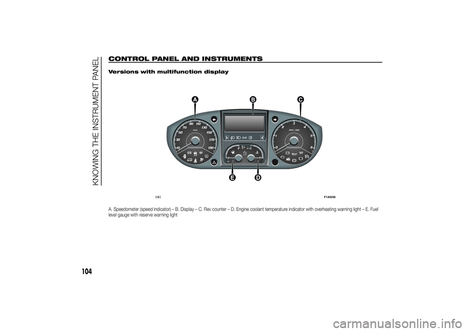
Versions with multifunction displayA. Speedometer (speed indicator) – B. Display – C. Rev counter – D. Engine coolant temperature indicator with overheating warning light – E. Fuel
level gauge with reserve warning light
141
F1A0356
104
KNOWING THE INSTRUMENT PANEL
Page 109 of 367
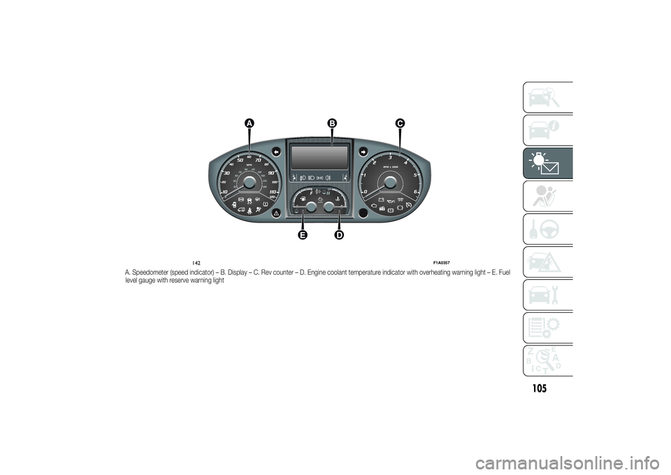
A. Speedometer (speed indicator) – B. Display – C. Rev counter – D. Engine coolant temperature indicator with overheating warning light – E. Fuel
level gauge with reserve warning light
142
F1A0357
105
Page 110 of 367
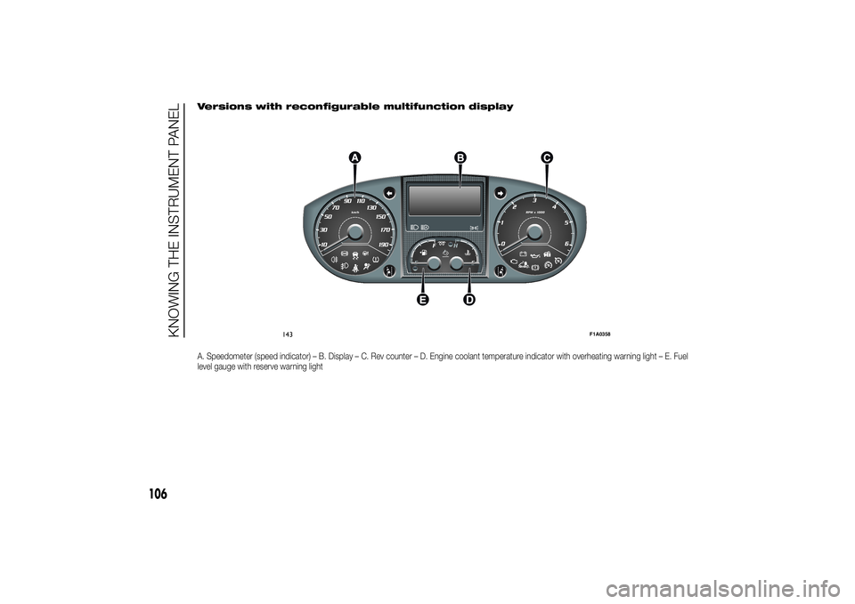
Versions with reconfigurable multifunction displayA. Speedometer (speed indicator) – B. Display – C. Rev counter – D. Engine coolant temperature indicator with overheating warning light – E. Fuel
level gauge with reserve warning light
143
F1A0358
106
KNOWING THE INSTRUMENT PANEL
Page 111 of 367
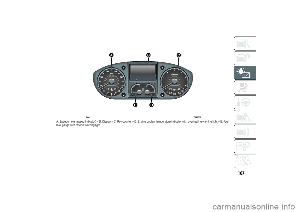
A. Speedometer (speed indicator) – B. Display – C. Rev counter – D. Engine coolant temperature indicator with overheating warning light – E. Fuel
level gauge with reserve warning light
144
F1A0359
107