FIAT DUCATO BASE CAMPER 2018 Owner handbook (in English)
Manufacturer: FIAT, Model Year: 2018, Model line: DUCATO BASE CAMPER, Model: FIAT DUCATO BASE CAMPER 2018Pages: 304, PDF Size: 14.93 MB
Page 11 of 304
Activation of thewarning light while
driving
If thewarning light turns on, this
means that the system is running a
self-diagnosis (for example due to
a voltage drop).
If thewarning light stays on,
contact a Fiat Dealership.
WARNING
1)The electronic components inside the
key may be damaged if the key is
subjected to strong shocks. In order to
ensure complete efficiency of the
electronic devices inside the key, it should
never be exposed to direct sunlight.
THE KEYS
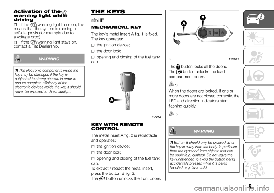
MECHANICAL KEY
The key's metal insert A fig. 1 is fixed.
The key operates:
the ignition device;
the door lock;
opening and closing of the fuel tank
cap.
KEY WITH REMOTE
CONTROL
The metal insert A fig. 2 is retractable
and operates:
the ignition device;
the door lock;
opening and closing of the fuel tank
cap.
To extract / retract the metal insert,
press the button B fig. 2.
The
button unlocks the front doors.The
button locks all the doors.
The
button unlocks the load
compartment doors.
1)
When the doors are locked, if one or
more doors are not closed correctly, the
LED and direction indicators start
flashing quickly.
1)
WARNING
1)Button B should only be pressed when
the key is away from the body, in particular
from the eyes and from objects that can
be spoilt (e.g. clothes). Do not leave the
key unattended to avoid the button being
accidentally pressed while it is being
handled, e.g. by a child.
1F1A0008
2F1A0004
9
Page 12 of 304
WARNING
1)Used batteries are harmful to the
environment. You can dispose of them
either in the correct containers as specified
by law or by taking them to a Fiat
Dealership, which will deal with their
disposal.
IGNITION SWITCH
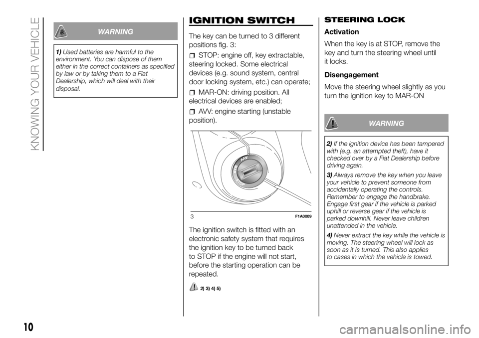
The key can be turned to 3 different
positions fig. 3:
STOP: engine off, key extractable,
steering locked. Some electrical
devices (e.g. sound system, central
door locking system, etc.) can operate;
MAR-ON: driving position. All
electrical devices are enabled;
AVV: engine starting (unstable
position).
The ignition switch is fitted with an
electronic safety system that requires
the ignition key to be turned back
to STOP if the engine will not start,
before the starting operation can be
repeated.
2) 3) 4) 5)
STEERING LOCK
Activation
When the key is at STOP, remove the
key and turn the steering wheel until
it locks.
Disengagement
Move the steering wheel slightly as you
turn the ignition key to MAR-ON
WARNING
2)If the ignition device has been tampered
with (e.g. an attempted theft), have it
checked over by a Fiat Dealership before
driving again.
3)Always remove the key when you leave
your vehicle to prevent someone from
accidentally operating the controls.
Remember to engage the handbrake.
Engage first gear if the vehicle is parked
uphill or reverse gear if the vehicle is
parked downhill. Never leave children
unattended in the vehicle.
4)Never extract the key while the vehicle is
moving. The steering wheel will lock as
soon as it is turned. This also applies
to cases in which the vehicle is towed.
3F1A0009
10
KNOWING YOUR VEHICLE
Page 13 of 304
5)Under no circumstances should
aftermarket operations be carried out
involving steering system or steering
column modifications (e.g. installation of
anti-theft device). This could negatively
affect performance and safety, invalidate
the warranty, cause serious safety
problems and also result in vehicle
non-compliance with type-approval
requirements.ELECTRONIC ALARM
(for versions/markets, where provided)
The alarm, in addition to all the remote
control functions described previously,
is controlled by the receiver located
under the dashboard near the fuse box.
Activation
With the doors and bonnet closed and
the ignition key either turned to STOP
or removed, point the key with the
remote control towards the vehicle and
press and release the lock button.
Excluding some markets, the system
produces an acoustic signal (beep) and
enables door locking.
The switching on of the alarm is
preceded by an self-diagnosis stage: if
a fault is detected, the system
produces another acoustic signal.
In this case, turn the alarm off by
pressing the "release doors/release
load compartment" button, check that
the doors and bonnet are properly
closed and turn the alarm back on by
pressing the lock button.
If a door or the bonnet is not properly
shut, it will be excluded from the testing
by the alarm system.If the alarm produces an acoustic signal
even when the doors and bonnet are
correctly closed, a fault has occurred in
the operation of the system. Contact
a Fiat Dealership.
IMPORTANT The alarm does not come
on when the central locking is activated
using the metal insert in the key.
IMPORTANT The alarm is adapted to
meet requirements in various countries.
Turning off
Press the door release/load
compartment release button on the key
with remote control.
The following operations are performed
(excluding some markets):
direction indicators flash twice;
there are two short acoustic signals
(beeps);
doors are unlocked.
IMPORTANT The alarm does not switch
off when the central opening is
activated using the metal insert in the
key.
11
Page 14 of 304
Disabling
To permanently disable the alarm (e.g.
during a long period of inactivity), simply
lock the vehicle by turning the metal
insert of the key with remote control in
the lock.
IMPORTANT If the batteries of the key
with the remote control run out or
the system fails, the alarm can
be switched off by placing the key in
the ignition switch and turning it to
MAR-ON.DOORS
DOOR CENTRAL
LOCKING/UNLOCKING
Locking from the outside
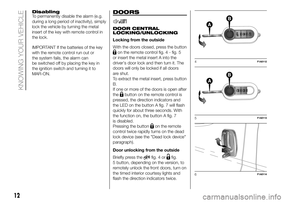
With the doors closed, press the button
on the remote control fig. 4 - fig. 5
or insert the metal insert A into the
driver's door lock and then turn it. The
doors will only be locked if all doors
are shut.
To extract the metal insert, press button
B.
If one or more of the doors is open after
the
button on the remote control is
pressed, the direction indicators and
the LED on the button A fig. 7 will flash
quickly for about three seconds. With
the function on, the button A fig. 7
is disabled.
Pressing the button
on the remote
control twice rapidly turns on the dead
lock device (see the "Dead lock device"
paragraph).
Door unlocking from the outside
Briefly press the
fig. 4 orfig.
5 button, depending on the version, to
remotely unlock the front doors, turn on
the timed interior courtesy lights and
flash the direction indicators twice.
4F1A0112
5F1A0113
6F1A0114
12
KNOWING YOUR VEHICLE
Page 15 of 304
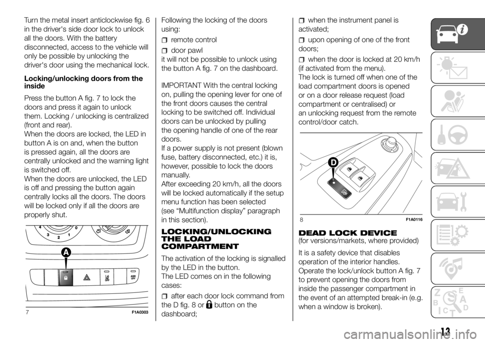
Turn the metal insert anticlockwise fig. 6
in the driver's side door lock to unlock
all the doors. With the battery
disconnected, access to the vehicle will
only be possible by unlocking the
driver's door using the mechanical lock.
Locking/unlocking doors from the
inside
Press the button A fig. 7 to lock the
doors and press it again to unlock
them. Locking / unlocking is centralized
(front and rear).
When the doors are locked, the LED in
button A is on and, when the button
is pressed again, all the doors are
centrally unlocked and the warning light
is switched off.
When the doors are unlocked, the LED
is off and pressing the button again
centrally locks all the doors. The doors
will be locked only if all the doors are
properly shut.Following the locking of the doors
using:
remote control
door pawl
it will not be possible to unlock using
the button A fig. 7 on the dashboard.
IMPORTANT With the central locking
on, pulling the opening lever for one of
the front doors causes the central
locking to be switched off. Individual
doors can be unlocked by pulling
the opening handle of one of the rear
doors.
If a power supply is not present (blown
fuse, battery disconnected, etc.) it is,
however, possible to lock the doors
manually.
After exceeding 20 km/h, all the doors
will be locked automatically if the setup
menu function has been selected
(see “Multifunction display” paragraph
in this section).
LOCKING/UNLOCKING
THE LOAD
COMPARTMENT
The activation of the locking is signalled
by the LED in the button.
The LED comes on in the following
cases:
after each door lock command from
the D fig. 8 or
button on the
dashboard;
when the instrument panel is
activated;
upon opening of one of the front
doors;
when the door is locked at 20 km/h
(if activated from the menu).
The lock is turned off when one of the
load compartment doors is opened
or on a door release request (load
compartment or centralised) or
an unlocking request from the remote
control/door catch.
DEAD LOCK DEVICE
(for versions/markets, where provided)
It is a safety device that disables
operation of the interior handles.
Operate the lock/unlock button A fig. 7
to prevent opening the doors from
inside the passenger compartment in
the event of an attempted break-in (e.g.
when a window is broken).
7F1A0303
8F1A0116
13
Page 16 of 304
The dead lock device therefore offers
the best possible protection against
break in attempts. We recommend
engaging it whenever the vehicle is
parked and left unattended.
6)
Device activation
The device turns on automatically on all
the doors when you press the
button
on the key with remote control fig. 4
twice rapidly.
The direction indicators flash 3 times
and the LED on the button A fig. 7
among the dashboard controls flashes
to indicate that the device has been
turned on.
If one or more of the doors is not
perfectly shut, the dead lock device will
not be activated, thus preventing a
person getting into the vehicle through
the open door and, on shutting, it,
remaining stuck inside the passenger
compartment.
Device deactivation
The system is disabled automatically on
every door in the following cases:
if the mechanical key is turned to the
opening position in the driver's door;
by unlocking the doors using the
remote control;
by turning the ignition key to the
MAR position.
SLIDING SIDE DOOR
7) 9)
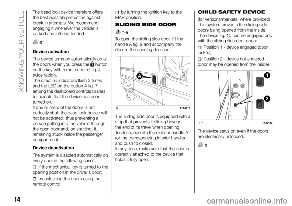
To open the sliding side door, lift the
handle A fig. 9 and accompany the
door in the opening direction.
The sliding side door is equipped with a
stop that prevents it sliding beyond
the end of its travel when opening.
To close, operate the exterior handle A
(or the corresponding interior handle)
and push to closed.
In any case, make sure that the door is
correctly attached to the device that
holds it fully open.CHILD SAFETY DEVICE
(for versions/markets, where provided)
This system prevents the sliding side
doors being opened from the inside.
The device fig. 10 can be engaged only
with the sliding side door open:
Position 1 - device engaged (door
locked)
Position 2 - device not engaged
(door may be opened from the inside)
The device stays on even if the doors
are electrically unlocked.
8)
9F1A0117
10F1A0143
14
KNOWING YOUR VEHICLE
Page 17 of 304
REAR DOOR WITH TWO
WINGS
10) 11)
Manual opening of the first swing
door from the outside
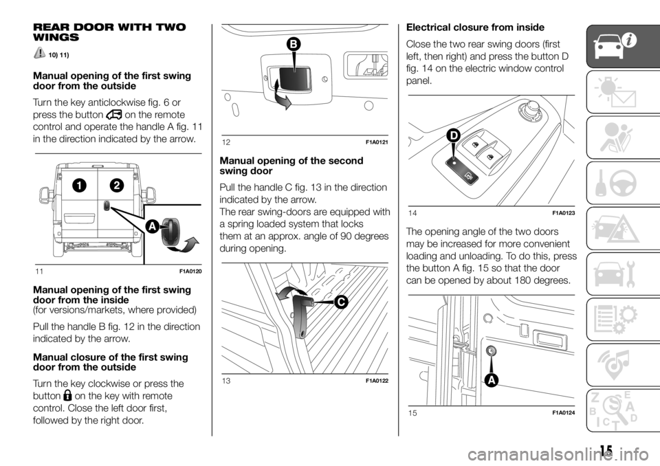
Turn the key anticlockwise fig. 6 or
press the button
on the remote
control and operate the handle A fig. 11
in the direction indicated by the arrow.
Manual opening of the first swing
door from the inside
(for versions/markets, where provided)
Pull the handle B fig. 12 in the direction
indicated by the arrow.
Manual closure of the first swing
door from the outside
Turn the key clockwise or press the
button
on the key with remote
control. Close the left door first,
followed by the right door.Manual opening of the second
swing door
Pull the handle C fig. 13 in the direction
indicated by the arrow.
The rear swing-doors are equipped with
a spring loaded system that locks
them at an approx. angle of 90 degrees
during opening.Electrical closure from inside
Close the two rear swing doors (first
left, then right) and press the button D
fig. 14 on the electric window control
panel.
The opening angle of the two doors
may be increased for more convenient
loading and unloading. To do this, press
the button A fig. 15 so that the door
can be opened by about 180 degrees.
11F1A0120
12F1A0121
13F1A0122
14F1A0123
15F1A0124
15
Page 18 of 304
MOVING FOOTBOARD
(for versions/markets, where provided)
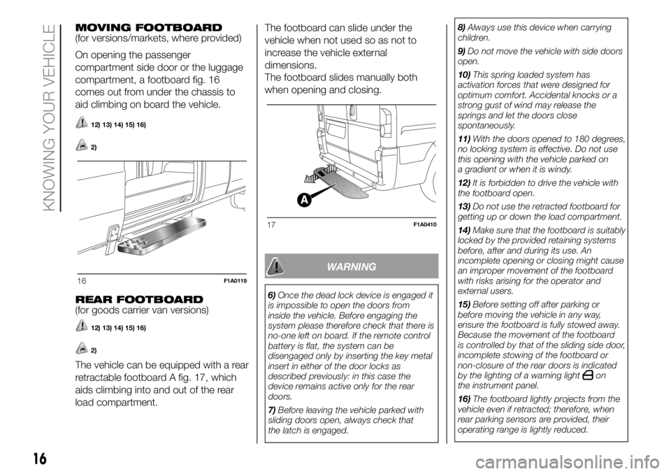
On opening the passenger
compartment side door or the luggage
compartment, a footboard fig. 16
comes out from under the chassis to
aid climbing on board the vehicle.
12) 13) 14) 15) 16)
2)
REAR FOOTBOARD
(for goods carrier van versions)
12) 13) 14) 15) 16)
2)
The vehicle can be equipped with a rear
retractable footboard A fig. 17, which
aids climbing into and out of the rear
load compartment.The footboard can slide under the
vehicle when not used so as not to
increase the vehicle external
dimensions.
The footboard slides manually both
when opening and closing.
WARNING
6)Once the dead lock device is engaged it
is impossible to open the doors from
inside the vehicle. Before engaging the
system please therefore check that there is
no-one left on board. If the remote control
battery is flat, the system can be
disengaged only by inserting the key metal
insert in either of the door locks as
described previously: in this case the
device remains active only for the rear
doors.
7)Before leaving the vehicle parked with
sliding doors open, always check that
the latch is engaged.8)Always use this device when carrying
children.
9)Do not move the vehicle with side doors
open.
10)This spring loaded system has
activation forces that were designed for
optimum comfort. Accidental knocks or a
strong gust of wind may release the
springs and let the doors close
spontaneously.
11)With the doors opened to 180 degrees,
no locking system is effective. Do not use
this opening with the vehicle parked on
a gradient or when it is windy.
12)It is forbidden to drive the vehicle with
the footboard open.
13)Do not use the retracted footboard for
getting up or down the load compartment.
14)Make sure that the footboard is suitably
locked by the provided retaining systems
before, after and during its use. An
incomplete opening or closing might cause
an improper movement of the footboard
with risks arising for the operator and
external users.
15)Before setting off after parking or
before moving the vehicle in any way,
ensure the footboard is fully stowed away.
Because the movement of the footboard
is controlled by that of the sliding side door,
incomplete stowing of the footboard or
non-closure of the rear doors is indicated
by the lighting of a warning light
on
the instrument panel.
16)The footboard lightly projects from the
vehicle even if retracted; therefore, when
rear parking sensors are provided, their
operating range is lightly reduced.
16F1A0119
17F1A0410
16
KNOWING YOUR VEHICLE
Page 19 of 304
WARNING
2)The footboard presence may reduce the
ramp approach angles; it is therefore
recommended, in case of a very steep
ramp, to be very careful in order not to
damage the footboard.
SEATS
17)
3)
Longitudinal adjustment
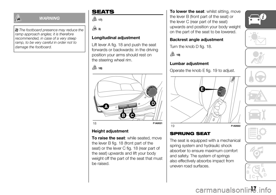
Lift lever A fig. 18 and push the seat
forwards or backwards: in the driving
position your arms should rest on
the steering wheel rim.
18)
Height adjustment
To raise the seat: while seated, move
the lever B fig. 18 (front part of the
seat) or the lever C fig. 18 (rear part of
the seat) upwards and lift your body
weight off the part of the seat that must
be raised.To lower the seat: whilst sitting, move
the lever B (front part of the seat) or
the lever C (rear part of the seat)
upwards and position your body weight
on the part of the seat to be lowered.
Backrest angle adjustment
Turn the knob D fig. 18.
19)
Lumbar adjustment
Operate the knob E fig. 19 to adjust.
SPRUNG SEAT
The seat is equipped with a mechanical
spring system and hydraulic shock
absorber to ensure maximum comfort
and safety. The system of springs
also effectively absorbs impact from
uneven road surfaces.
18F1A002119F1A0022
17
Page 20 of 304
See the description in the "Seats"
section for the lengthwise adjustments,
height adjustments, backrest
adjustment, lumbar adjustment and
armrest adjustment.
Ballast weight adjustment
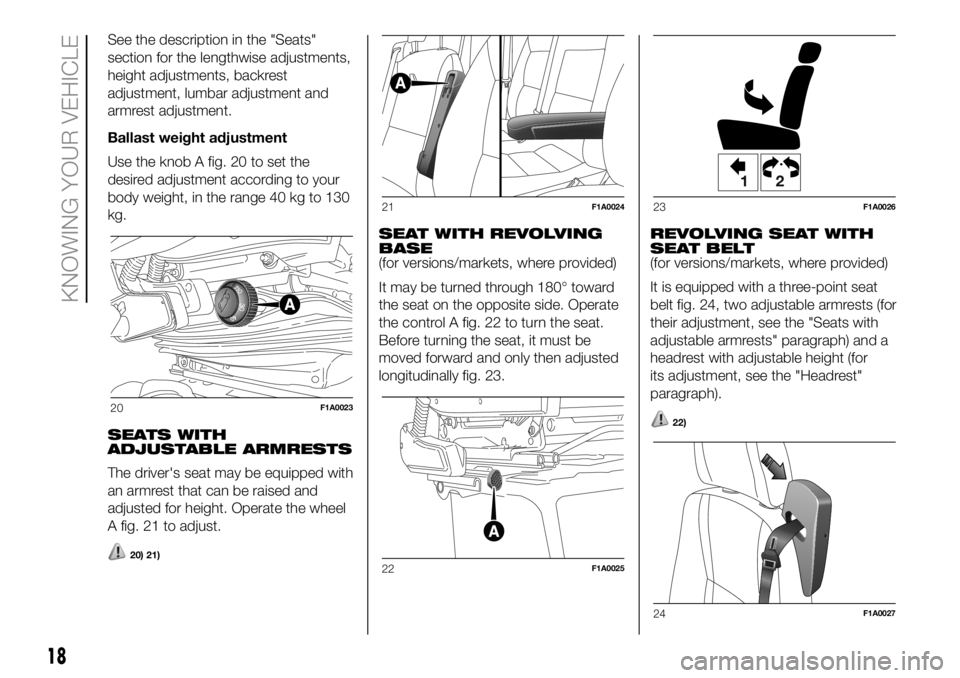
Use the knob A fig. 20 to set the
desired adjustment according to your
body weight, in the range 40 kg to 130
kg.
SEATS WITH
ADJUSTABLE ARMRESTS
The driver's seat may be equipped with
an armrest that can be raised and
adjusted for height. Operate the wheel
A fig. 21 to adjust.
20) 21)
SEAT WITH REVOLVING
BASE
(for versions/markets, where provided)
It may be turned through 180° toward
the seat on the opposite side. Operate
the control A fig. 22 to turn the seat.
Before turning the seat, it must be
moved forward and only then adjusted
longitudinally fig. 23.REVOLVING SEAT WITH
SEAT BELT
(for versions/markets, where provided)
It is equipped with a three-point seat
belt fig. 24, two adjustable armrests (for
their adjustment, see the "Seats with
adjustable armrests" paragraph) and a
headrest with adjustable height (for
its adjustment, see the "Headrest"
paragraph).
22)20F1A0023
21F1A0024
22F1A0025
12
23F1A0026
24F1A0027
18
KNOWING YOUR VEHICLE