window FIAT FIORINO 2007 Owner handbook (in English)
[x] Cancel search | Manufacturer: FIAT, Model Year: 2007, Model line: FIORINO, Model: FIAT FIORINO 2007Pages: 210, PDF Size: 3.22 MB
Page 52 of 210
51
SAFETY
STARTING
AND DRIVING
WARNING
LIGHTS AND
MESSAGES
IN AN
EMERGENCY
MAINTENANCE
AND CARE
TECHNICAL
SPECIFICATIONS
INDEX
DASHBOARD
AND CONTROLS
WINDOW WASHING
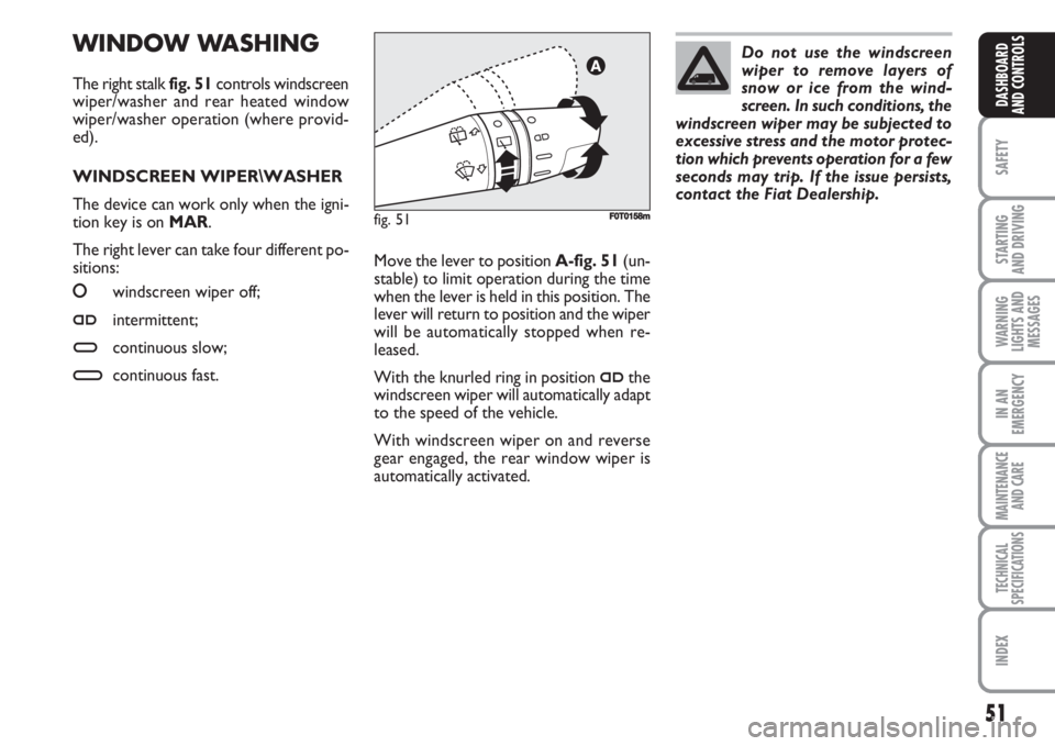
The right stalk fig. 51controls windscreen
wiper/washer and rear heated window
wiper/washer operation (where provid-
ed).
WINDSCREEN WIPER\WASHER
The device can work only when the igni-
tion key is on MAR.
The right lever can take four different po-
sitions:
O
O
windscreen wiper off;
≤intermittent;
≥continuous slow;
¥continuous fast.
fig. 51F0T0158m
Move the lever to position A-fig. 51(un-
stable) to limit operation during the time
when the lever is held in this position. The
lever will return to position and the wiper
will be automatically stopped when re-
leased.
With the knurled ring in position
≤the
windscreen wiper will automatically adapt
to the speed of the vehicle.
With windscreen wiper on and reverse
gear engaged, the rear window wiper is
automatically activated.Do not use the windscreen
wiper to remove layers of
snow or ice from the wind-
screen. In such conditions, the
windscreen wiper may be subjected to
excessive stress and the motor protec-
tion which prevents operation for a few
seconds may trip. If the issue persists,
contact the Fiat Dealership.
Page 53 of 210
52
SAFETY
STARTING
AND DRIVING
WARNING
LIGHTS AND
MESSAGES
IN AN
EMERGENCY
MAINTENANCE
AND CARE
TECHNICAL
SPECIFICATIONS
INDEX
DASHBOARD
AND CONTROLS
REAR WINDOW WIPER/
WASHER (where provided)
The device can work only when the igni-
tion key is on MAR.
Activation
Turn the knurled ring to
'to operate the
rear window wiper as follows:
❒intermittent operation if the wind-
screen wiper is off;
❒synchronised with the windscreen
wiper (but with half stroke frequency);
❒continuous operation with reverse gear
engaged and windscreen wiper on.
With windscreen wiper on and reverse
gear engaged, rear window wiping will be
continuous.
Pushing the stalk towards the dashboard
(unstable position) will activate the rear
window washer. Keeping the stalk pushed
for over half a second will also activate the
rear window wiper. Releasing the stalk will
activate the smart washing function as de-
scribed for the windscreen wiper.Deactivation
Operation will stop when releasing the
stalk.
Do not use the rear window
wiper to remove layers of
snow or ice from the rear win-
dow. In such conditions, the
windscreen wiper may be subjected to
excessive stress and the motor protec-
tion which prevents operation for a few
seconds may trip. If rear window wiper
operation is not reset, contact the
Fiat Dealership.
“Smart washing” function
Pull the stalk towards the steering wheel
(unstable position) to operate the wind-
screen washer jet.
Keeping the stalk pulled for more than half
a second, with just one movement it is
possible to operate the washer jet and the
wiper at the same time.
The wiper stops working three strokes af-
ter releasing the stalk.
A further stroke after approx. 6 seconds
completes the wiping cycle.
Page 61 of 210
60
SAFETY
STARTING
AND DRIVING
WARNING
LIGHTS AND
MESSAGES
IN AN
EMERGENCY
MAINTENANCE
AND CARE
TECHNICAL
SPECIFICATIONS
INDEX
DASHBOARD
AND CONTROLS
fig. 66FF0T0134m
fig. 67
A
F0T0135m
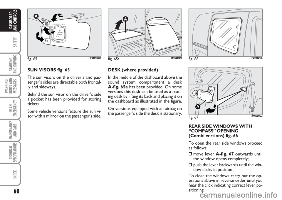
SUN VISORS fig. 65
The sun visors on the driver’s and pas-
senger’s sides are directable both frontal-
ly and sideways.
Behind the sun visor on the driver’s side
a pocket has been provided for storing
tickets.
Some vehicle versions feature the sun vi-
sor with a mirror on the passenger’s side.DESK (where provided)
In the middle of the dashboard above the
sound system compartment a desk
A-fig. 65ahas been provided. On some
versions this desk can be used as a read-
ing desk by lifting its back and placing it on
the dashboard as illustrated in the figure.
On versions equipped with an airbag on
the passenger’s side the desk is stationary.
fig. 65F0T0188m
REAR SIDE WINDOWS WITH
“COMPASS” OPENING
(Combi versions) fig. 66
To open the rear side windows proceed
as follows:
❒move lever A-fig. 67outwards until
the window opens completely;
❒push the lever backwards until the win-
dow clicks in position.
To close the windows carry out the op-
erations above in reverse order until you
hear the click indicating correct lever po-
sitioning.
fig. 65aF0T0204m
Page 67 of 210
66
SAFETY
STARTING
AND DRIVING
WARNING
LIGHTS AND
MESSAGES
IN AN
EMERGENCY
MAINTENANCE
AND CARE
TECHNICAL
SPECIFICATIONS
INDEX
DASHBOARD
AND CONTROLS
WINDOW WINDERS
FRONT POWER
WINDOWS (where provided)
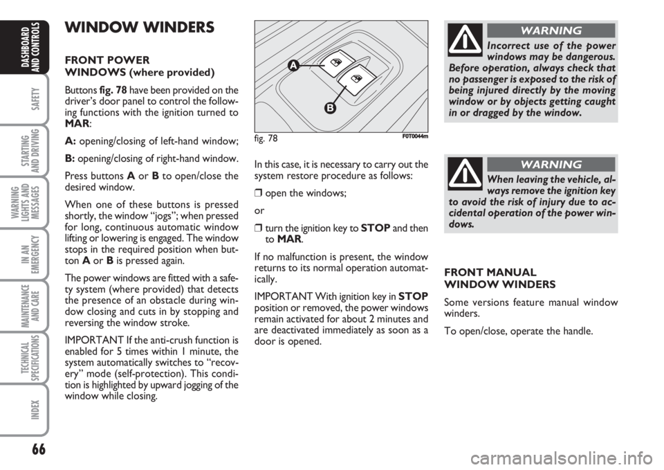
Buttons fig. 78have been provided on the
driver’s door panel to control the follow-
ing functions with the ignition turned to
MAR:
A:opening/closing of left-hand window;
B:opening/closing of right-hand window.
Press buttons Aor Bto open/close the
desired window.
When one of these buttons is pressed
shortly, the window “jogs”; when pressed
for long, continuous automatic window
lifting or lowering is engaged. The window
stops in the required position when but-
ton Aor Bis pressed again.
The power windows are fitted with a safe-
ty system (where provided) that detects
the presence of an obstacle during win-
dow closing and cuts in by stopping and
reversing the window stroke.
IMPORTANT If the anti-crush function is
enabled for 5 times within 1 minute, the
system automatically switches to “recov-
ery” mode (self-protection). This condi-
tion is highlighted by upward jogging of the
window while closing.In this case, it is necessary to carry out the
system restore procedure as follows:
❒open the windows;
or
❒turn the ignition key to STOPand then
to MAR.
If no malfunction is present, the window
returns to its normal operation automat-
ically.
IMPORTANT With ignition key in STOP
position or removed, the power windows
remain activated for about 2 minutes and
are deactivated immediately as soon as a
door is opened.
fig. 78F0T0044m
Incorrect use of the power
windows may be dangerous.
Before operation, always check that
no passenger is exposed to the risk of
being injured directly by the moving
window or by objects getting caught
in or dragged by the window.
WARNING
When leaving the vehicle, al-
ways remove the ignition key
to avoid the risk of injury due to ac-
cidental operation of the power win-
dows.
WARNING
FRONT MANUAL
WINDOW WINDERS
Some versions feature manual window
winders.
To open/close, operate the handle.
Page 69 of 210
68
SAFETY
STARTING
AND DRIVING
WARNING
LIGHTS AND
MESSAGES
IN AN
EMERGENCY
MAINTENANCE
AND CARE
TECHNICAL
SPECIFICATIONS
INDEX
DASHBOARD
AND CONTROLS
REMOVING THE REAR
WINDOW SHELF
(Combi versions)
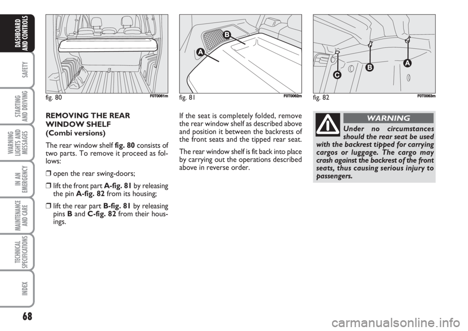
The rear window shelf fig. 80consists of
two parts. To remove it proceed as fol-
lows:
❒open the rear swing-doors;
❒lift the front part A-fig. 81by releasing
the pin A-fig. 82from its housing;
❒lift the rear part B-fig. 81by releasing
pins Band C-fig. 82from their hous-
ings.If the seat is completely folded, remove
the rear window shelf as described above
and position it between the backrests of
the front seats and the tipped rear seat.
The rear window shelf is fit back into place
by carrying out the operations described
above in reverse order.
fig. 80F0T0061mfig. 81
A
A
F0T0062mfig. 82
AAA
F0T0063m
Under no circumstances
should the rear seat be used
with the backrest tipped for carrying
cargos or luggage. The cargo may
crash against the backrest of the front
seats, thus causing serious injury to
passengers.
WARNING
Page 70 of 210
69
SAFETY
STARTING
AND DRIVING
WARNING
LIGHTS AND
MESSAGES
IN AN
EMERGENCY
MAINTENANCE
AND CARE
TECHNICAL
SPECIFICATIONS
INDEX
DASHBOARD
AND CONTROLS
EXPANDING THE BOOT
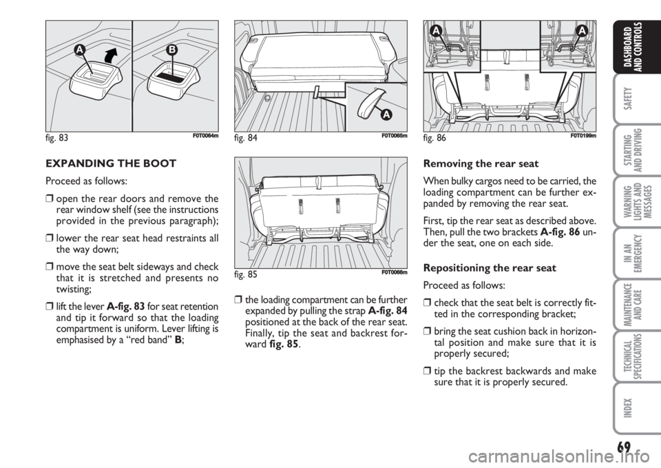
Proceed as follows:
❒open the rear doors and remove the
rear window shelf (see the instructions
provided in the previous paragraph);
❒lower the rear seat head restraints all
the way down;
❒move the seat belt sideways and check
that it is stretched and presents no
twisting;
❒lift the lever A-fig. 83for seat retention
and tip it forward so that the loading
compartment is uniform. Lever lifting is
emphasised by a “red band” B;❒the loading compartment can be further
expanded by pulling the strap A-fig. 84
positioned at the back of the rear seat.
Finally, tip the seat and backrest for-
ward fig. 85.Removing the rear seat
When bulky cargos need to be carried, the
loading compartment can be further ex-
panded by removing the rear seat.
First, tip the rear seat as described above.
Then, pull the two brackets A-fig. 86un-
der the seat, one on each side.
Repositioning the rear seat
Proceed as follows:
❒check that the seat belt is correctly fit-
ted in the corresponding bracket;
❒bring the seat cushion back in horizon-
tal position and make sure that it is
properly secured;
❒tip the backrest backwards and make
sure that it is properly secured.
fig. 83
AB
F0T0064mfig. 84F0T0065m
fig. 85F0T0066m
fig. 86
AA
F0T0199m
Page 80 of 210
79
SAFETY
STARTING
AND DRIVING
WARNING
LIGHTS AND
MESSAGES
IN AN
EMERGENCY
MAINTENANCE
AND CARE
TECHNICAL
SPECIFICATIONS
INDEX
DASHBOARD
AND CONTROLS
SOUND SYSTEM
(where provided)
For the operation of the radio with
CD/MP3 CD (where provided), read the
instructions for use given in the Supple-
ment attached to the Owner Handbook.
BASIC EQUIPMENT
The system consists of:
❒sound system power supply cables;
❒front speakers cables (positioned on the
panels of the rear door mirrors);
❒loud speakers cables on front door pan-
els;
❒rear loud speakers cables (positioned
alongside the rear window shelf)
(where provided);
❒sound system housing;
❒aerial power supply cable.EXTRA EQUIPMENT
The system consists of:
❒sound system power supply cables;
❒front loud speakers cables (positioned
on the panels of the rear door mirrors);
❒loud speakers cables on front door pan-
els;
❒rear loud speakers cables (positioned
alongside the rear window shelf)
(where provided);
❒2 tweeters positioned on the panels of
the rear door mirrors;
❒2 midwoofers on front door bottom;
❒2 rear loud speakers (positioned along-
side the rear window shelf) (where pro-
vided);
❒sound system housing;
❒aerial power supply cable;
❒aerial.INSTALLING THE
SOUND SYSTEM
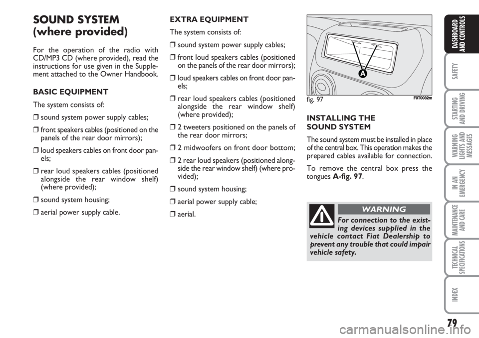
The sound system must be installed in place
of the central box. This operation makes the
prepared cables available for connection.
To remove the central box press the
tongues A-fig. 97.
fig. 97F0T0032m
For connection to the exist-
ing devices supplied in the
vehicle contact Fiat Dealership to
prevent any trouble that could impair
vehicle safety.
WARNING
Page 107 of 210
106
SAFETY
WARNING
LIGHTS AND
MESSAGES
IN AN
EMERGENCY
MAINTENANCE
AND CARE
TECHNICAL
SPECIFICATIONS
INDEX
DASHBOARDAND CONTROLS
STARTING
AND DRIVING
CONTAINING
RUNNING COSTS
Here are some useful tips to save fuel and
minimize polluting emissions of CO
2and
other pollutants (nitric oxide, unburnt hy-
drocarbons, fine dusts etc…).GENERAL REMARKS
Vehicle maintenance
Have checks and adjustments carried out
in accordance with the “Scheduled Service
Plan”.
Tyres
Check tyre pressure regularly at least
once every four weeks: excessively low
pressure will increase consumption be-
cause rolling resistance will be higher.
Unnecessary loads
Do not travel with an overloaded boot.
The weight of the vehicle (especially when
driving in town) and its trim greatly affect
fuel consumption and stability.
Roof rack/ski rack
Remove the roof rack or the ski rack from
the roof after use. These accessories de-
crease aerodynamic penetration of the ve-
hicle and have a negative effect on fuel
consumption. It is better to use a trailer
to transport particularly bulky objects.Electric devices
Use electric devices only for the amount
of time needed. The rear heated window,
additional headlights, windscreen wipers
and heater fan need a considerable
amount of energy, therefore increasing fu-
el consumption (up to +25% in the urban
cycle).
Climate control
The climate control system leads to high-
er fuel consumption (up to +20% on av-
erage): use air vents only when the ex-
ternal temperature allows it.
Spoilers
The use of non-certified spoilers may ad-
versely affect air drag and fuel consump-
tion levels.
Page 111 of 210
110
SAFETY
WARNING
LIGHTS AND
MESSAGES
IN AN
EMERGENCY
MAINTENANCE
AND CARE
TECHNICAL
SPECIFICATIONS
INDEX
DASHBOARDAND CONTROLS
STARTING
AND DRIVING
SNOW CHAINS
Use of snow chains should be in compli-
ance with local regulations.
The snow chains may be applied only to
the front wheel tyres (drive wheels).
Check the tension of the chains after the
first few metres have been driven.
PROLONGED VEHICLE
INACTIVITY
If the vehicle needs to be stopped for longer
than one month, the following precautions
must be taken:
❒park the vehicle indoors in a dry and, pos-
sibly, well-ventilated place;
❒engage a gear and check that the hand-
brake is not engaged;
❒disconnect the negative terminal of the
battery and check charge (see paragraph
“Battery” in section “Maintenance and
care”);
❒clean and protect the painted parts using
protective wax;❒clean and protect the shiny metal parts
using special compounds readily available;
❒sprinkle talcum powder on the rubber
windscreen and rear window wiper
blades and lift them off the glass;
❒slightly open the windows;
❒cover the vehicle with a piece of fabric or
perforated plastic sheet; do not use com-
pact plastic tarpaulins, which prevent hu-
midity from evaporating from the surface
of the vehicle;
❒inflate tyres to a pressure of +0.5 bar
above the normal specified pressure and
check it at intervals;
❒do not drain the engine cooling system. Keep your speed down when
snow chains are fitted. Do not
exceed 50 km/h. Avoid pot-
holes, steps and pavements
and also avoid driving long distances on
roads not covered with snow in order
to prevent damaging the vehicle and
the roadbed.
Page 150 of 210
149
SAFETY
MAINTENANCE
AND CARE
TECHNICAL
SPECIFICATIONS
INDEX
DASHBOARDAND CONTROLS
STARTING
AND DRIVING
WARNING
LIGHTS AND
MESSAGES
IN AN
EMERGENCY
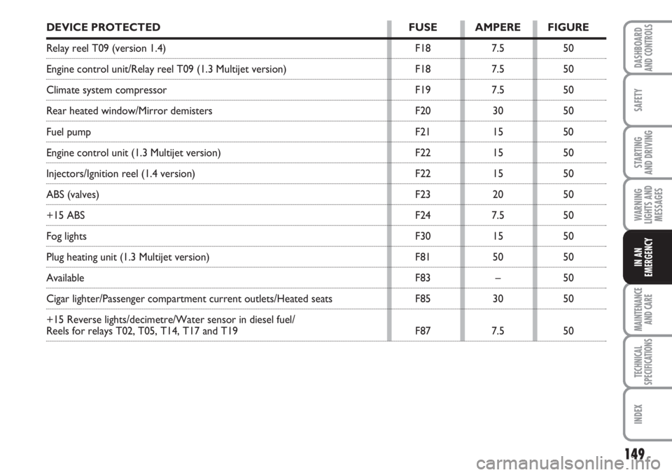
DEVICE PROTECTED FUSE AMPERE FIGURE
Relay reel T09 (version 1.4) F18 7.5 50
Engine control unit/Relay reel T09 (1.3 Multijet version) F18 7.5 50
Climate system compressor F19 7.5 50
Rear heated window/Mirror demisters F20 30 50
Fuel pump F21 15 50
Engine control unit (1.3 Multijet version) F22 15 50
Injectors/Ignition reel (1.4 version) F22 15 50
ABS (valves) F23 20 50
+15 ABS F24 7.5 50
Fog lights F30 15 50
Plug heating unit (1.3 Multijet version) F81 50 50
Available F83 – 50
Cigar lighter/Passenger compartment current outlets/Heated seats F85 30 50
+15 Reverse lights/decimetre/Water sensor in diesel fuel/
Reels for relays T02, T05, T14, T17 and T19 F87 7.5 50