technical specifications FIAT FIORINO 2008 Owner handbook (in English)
[x] Cancel search | Manufacturer: FIAT, Model Year: 2008, Model line: FIORINO, Model: FIAT FIORINO 2008Pages: 210, PDF Size: 3.51 MB
Page 75 of 210
74
SAFETY
STARTING
AND DRIVING
WARNING
LIGHTS AND
MESSAGES
IN AN
EMERGENCY
MAINTENANCE
AND CARE
TECHNICAL
SPECIFICATIONS
INDEX
DASHBOARD
AND CONTROLS
ABS SYSTEM
The vehicle is fitted with an ABS braking
system, which prevents the wheels from
locking when braking, makes the most of
road grip and gives the best control when
emergency braking under difficult road
conditions.
The system is completed by EBD (Elec-
tronic Braking Force Distribution), which
distributes the braking action between
front and rear wheels.
IMPORTANT To achieve maximum effi-
ciency of the braking system, a running-
in period of about 500 km is required.
During this time, avoid sudden, repeated
and prolonged braking.ABS SYSTEM INTERVENTION
Intervention of the ABS is detected by a
slight pulsing of the brake pedal accompa-
nied by noise: such an event indicates that
you need to adjust your speed to the type
of road on which you are travelling.
When the ABS cuts in, and
you feel the brake pedal pul-
sating, do not remove your foot, but
keep it pressed; in doing so you will
stop in the shortest amount of space
possible depending on the current
road conditions.
WARNING
When the ABS trips, it means
that you are approaching
the grip limit between tyres and road:
slow down to exploit all the available
grip.
WARNING
The ABS system exploits the
tyre-road grip at best, but it
cannot improve it. Therefore, you
should take great care when driving
on slippery surfaces without taking
unnecessary risks.
WARNING
036-082 Fiorino GB 2ed 13-02-2008 9:39 Pagina 74
Page 76 of 210
75
SAFETY
STARTING
AND DRIVING
WARNING
LIGHTS AND
MESSAGES
IN AN
EMERGENCY
MAINTENANCE
AND CARE
TECHNICAL
SPECIFICATIONS
INDEX
DASHBOARD
AND CONTROLS
FAILURE INDICATIONS
ABS failure
ABS failure is indicated by the turning on
of warning light
>on the instrument pan-
el (together with the dedicated message
on the display in some versions) (see sec-
tion “Warning lights and messages”).
In the case, the braking system preserves
its efficiency, but cannot rely on the ex-
tra potentials offered by the ABS system.
Drive carefully to the nearest Fiat Deal-
ership to have the system checked.EBD failure
EBD failure is indicated by the turning on
of warning lights
>and xon the instru-
ment panel (together with the dedicated
message on the display in some versions)
(see section “Warning lights and mes-
sages”).
In this case, the rear wheels may sudden-
ly lock and the vehicle may swerve. Dri-
ve carefully to the nearest Fiat Dealership
to have the system checked.If warning light xonly lights
up on the instrument panel
(with a message on the display in
some versions), immediately stop the
vehicle and go to the nearest Fiat
Dealership. Leakage of hydraulic flu-
id from the braking system jeopardis-
es the functionality of the braking sys-
tem, either of the conventional type
or with ABS.
WARNING
036-082 Fiorino GB 2ed 13-02-2008 9:39 Pagina 75
Page 77 of 210
76
SAFETY
STARTING
AND DRIVING
WARNING
LIGHTS AND
MESSAGES
IN AN
EMERGENCY
MAINTENANCE
AND CARE
TECHNICAL
SPECIFICATIONS
INDEX
DASHBOARD
AND CONTROLS
EOBD SYSTEM
The EOBD system (European On Board
Diagnosis) allows continuous diagnosis of
emission-related components of the vehi-
cle. It also alerts the driver, by switching
on of the warning light Uon the instru-
ment panel (together with relevant mes-
sage on the display in some versions)
when these components are no longer in
peak conditions (see section “Warning
lights and messages”).
The objective of this system is:
❒to keep the system efficiency under
control;
❒to warn about increased emissions due
to a vehicle malfunction;
❒to warn of the need to replace deteri-
orated components.The system also has a diagnostic connector
that can be interfaced with appropriate
tools, which makes it possible to read the
error codes stored in the control unit to-
gether with a series of specific parameters
for engine operation and diagnosis.
This check can also be carried out by the
traffic police.
IMPORTANT After eliminating the prob-
lem, to check the system completely, Fi-
at Dealerships are obliged to run a bench
test and, if necessary, road tests which
may also call for a long journey.Go to a Fiat Dealership as
soon as possible if warning
light Udoes not light up when the
key is turned to MAR or if, during
travel, the warning light comes on ei-
ther steady or blinking (along with a
message on the display). The opera-
tion of the warning light Umay be
checked by the traffic police using
specific devices. Follow the laws in
force in the country where you are
driving.
WARNING
036-082 Fiorino GB 2ed 13-02-2008 9:39 Pagina 76
Page 78 of 210
77
SAFETY
STARTING
AND DRIVING
WARNING
LIGHTS AND
MESSAGES
IN AN
EMERGENCY
MAINTENANCE
AND CARE
TECHNICAL
SPECIFICATIONS
INDEX
DASHBOARD
AND CONTROLS
PARKING SENSORS
(where provided)
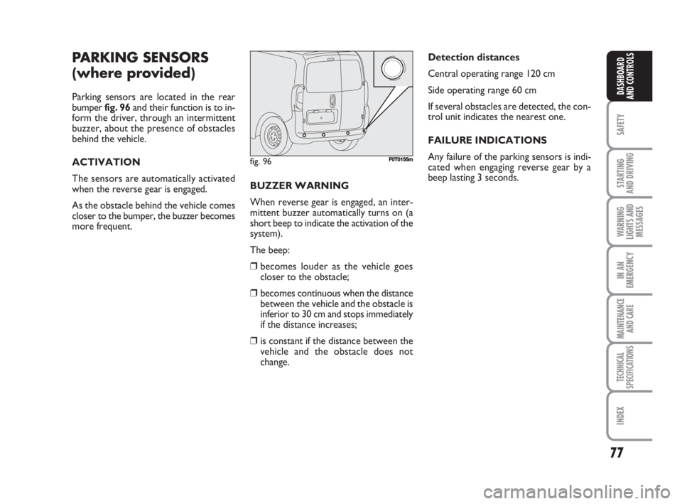
Parking sensors are located in the rear
bumper fig. 96and their function is to in-
form the driver, through an intermittent
buzzer, about the presence of obstacles
behind the vehicle.
ACTIVATION
The sensors are automatically activated
when the reverse gear is engaged.
As the obstacle behind the vehicle comes
closer to the bumper, the buzzer becomes
more frequent.BUZZER WARNING
When reverse gear is engaged, an inter-
mittent buzzer automatically turns on (a
short beep to indicate the activation of the
system).
The beep:
❒becomes louder as the vehicle goes
closer to the obstacle;
❒becomes continuous when the distance
between the vehicle and the obstacle is
inferior to 30 cm and stops immediately
if the distance increases;
❒is constant if the distance between the
vehicle and the obstacle does not
change.Detection distances
Central operating range 120 cm
Side operating range 60 cm
If several obstacles are detected, the con-
trol unit indicates the nearest one.
FAILURE INDICATIONS
Any failure of the parking sensors is indi-
cated when engaging reverse gear by a
beep lasting 3 seconds.
fig. 96F0T0155m
036-082 Fiorino GB 2ed 13-02-2008 9:39 Pagina 77
Page 79 of 210
78
SAFETY
STARTING
AND DRIVING
WARNING
LIGHTS AND
MESSAGES
IN AN
EMERGENCY
MAINTENANCE
AND CARE
TECHNICAL
SPECIFICATIONS
INDEX
DASHBOARD
AND CONTROLS
OPERATION
WITH TRAILER
Parking sensor operation is automatically
disabled when the electric cable plug of the
trailer is fitted into the vehicle tow hook
socket.
Sensors are automatically enabled again
when removing the trailer cable plug.GENERAL WARNINGS
❒When parking, take the utmost care to
obstacles that may be set above or un-
der the sensors.
❒Objects located near the vehicle back,
under certain circumstances, are not
detected and could therefore cause
damage to the vehicle or become dam-
aged.
❒Indications sent by the sensors can be
altered by dirt, snow or ice deposited
on the sensors or by ultrasound sys-
tems (e.g. truck pneumatic brakes or
pneumatic hammers) near the vehicle.
❒For correct parking sensor operation
the swing-doors must be closed. Open
swing-doors may produce incorrect in-
dications by the system. The rear doors
must always be closed. The sensors must be clean
from mud, dirt, snow or ice in
order to work correctly. Be
careful not to scratch or dam-
age the sensors while cleaning them.
Avoid using dry, rough or hard cloths.
Wash the sensors with clean water with
the addition of car shampoo, if neces-
sary. In washing stations, clean sensors
quickly keeping the vapour jet/high
pressure washing nozzles at 10 cm at
least from the sensors.
The driver is fully responsible
for parking operations and
other dangerous manoeuvres. Make
sure that no-one is standing in the
area, especially children or animals.
Parking sensors are designed to assist
drivers, who must always pay the ut-
most attention during potentially
dangerous manoeuvres even if they
are performed at low speed.
WARNING
036-082 Fiorino GB 2ed 13-02-2008 9:39 Pagina 78
Page 80 of 210
79
SAFETY
STARTING
AND DRIVING
WARNING
LIGHTS AND
MESSAGES
IN AN
EMERGENCY
MAINTENANCE
AND CARE
TECHNICAL
SPECIFICATIONS
INDEX
DASHBOARD
AND CONTROLS
SOUND SYSTEM
(where provided)
For the operation of the radio with
CD/MP3 CD (where provided), read the
instructions for use given in the Supple-
ment attached to the Owner Handbook.
BASIC EQUIPMENT
The system consists of:
❒sound system power supply cables;
❒front speakers cables (positioned on the
panels of the rear door mirrors);
❒loud speakers cables on front door pan-
els;
❒rear loud speakers cables (positioned
alongside the rear window shelf)
(where provided);
❒sound system housing;
❒aerial power supply cable.EXTRA EQUIPMENT
The system consists of:
❒sound system power supply cables;
❒front loud speakers cables (positioned
on the panels of the rear door mirrors);
❒loud speakers cables on front door pan-
els;
❒rear loud speakers cables (positioned
alongside the rear window shelf)
(where provided);
❒2 tweeters positioned on the panels of
the rear door mirrors;
❒2 midwoofers on front door bottom;
❒2 rear loud speakers (positioned along-
side the rear window shelf) (where pro-
vided);
❒sound system housing;
❒aerial power supply cable;
❒aerial.INSTALLING THE
SOUND SYSTEM
The sound system must be installed in place
of the central box. This operation makes the
prepared cables available for connection.
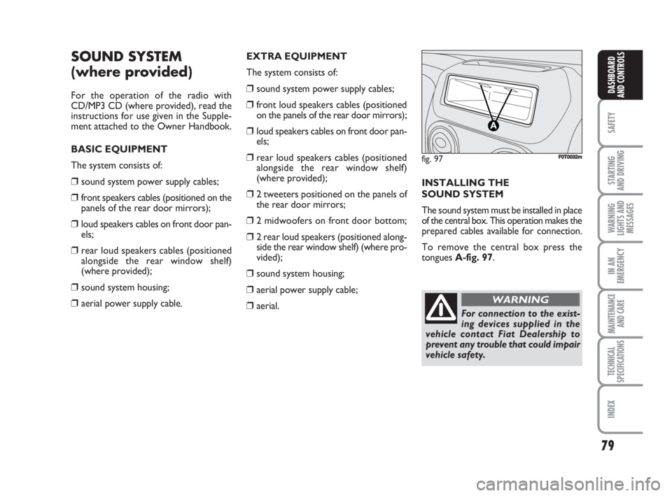
To remove the central box press the
tongues A-fig. 97.
fig. 97F0T0032m
For connection to the exist-
ing devices supplied in the
vehicle contact Fiat Dealership to
prevent any trouble that could impair
vehicle safety.
WARNING
036-082 Fiorino GB 2ed 13-02-2008 9:39 Pagina 79
Page 81 of 210
80
SAFETY
STARTING
AND DRIVING
WARNING
LIGHTS AND
MESSAGES
IN AN
EMERGENCY
MAINTENANCE
AND CARE
TECHNICAL
SPECIFICATIONS
INDEX
DASHBOARD
AND CONTROLS
ELECTRICAL/ELECTRONIC
DEVICES INSTALLATION
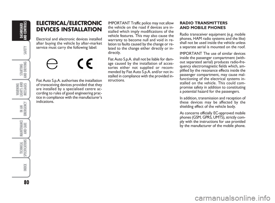
Electrical and electronic devices installed
after buying the vehicle by after-market
service must carry the following label:
Fiat Auto S.p.A. authorises the installation
of transceiving devices provided that they
are installed by a specialised centre ac-
cording to rules of good engineering prac-
tice in compliance with the manufacturer’s
indications.IMPORTANT Traffic police may not allow
the vehicle on the road if devices are in-
stalled which imply modifications of the
vehicle features. This may also cause the
warranty to become null and void in re-
lation to faults caused by the change or re-
lated to the change either directly or in-
directly.
Fiat Auto S.p.A. shall not be liable for dam-
age caused by the installation of acces-
sories either not supplied or recom-
mended by Fiat Auto S.p.A. and/or not in-
stalled in compliance with the provided in-
structions.RADIO TRANSMITTERS
AND MOBILE PHONES
Radio transceiver equipment (e.g. mobile
phones, HAM radio systems and the like)
shall not be used inside the vehicle unless
a separate aerial is mounted on the roof.
IMPORTANT The use of similar devices
inside the passenger compartment (with-
out separated aerial) produces radio-fre-
quency electromagnetic fields which, am-
plified by the resonance effects inside the
passenger compartment, may cause mal-
functioning of the electrical systems in-
stalled on the vehicle. This could com-
promise safety in addition to constituting
a potential hazard for the passengers.
In addition, transmission and reception of
these devices may be affected by the
shielding effect of the vehicle body.
As concerns officially EC-approved mobile
phones (GSM, GPRS, UMTS), strictly com-
ply with the instructions for use provided
by the manufacturer of the mobile phone.
036-082 Fiorino GB 2ed 13-02-2008 9:39 Pagina 80
Page 82 of 210
81
SAFETY
STARTING
AND DRIVING
WARNING
LIGHTS AND
MESSAGES
IN AN
EMERGENCY
MAINTENANCE
AND CARE
TECHNICAL
SPECIFICATIONS
INDEX
DASHBOARD
AND CONTROLS
VEHICLE REFUELLING
PETROL ENGINES
Use unleaded petrol only with octane
number (R.O.N.) not lower than 95.
IMPORTANT An inefficient catalyst leads
to harmful exhaust emissions, thus con-
tributing to air pollution.
IMPORTANT Never use leaded petrol,
even in small amount or in an emergency,
as this would damage the catalyst beyond
repair.DIESEL ENGINES
Operation at low temperatures
If the outside temperature is very low, the
diesel thickens due to the formation of
paraffin clots with consequent anomalous
operation of the fuel supply system.
In order to avoid these problems, different
types of diesel are distributed according to
the season: summer type, winter type and
arctic type (cold, mountain areas). If refu-
elling with diesel fuel whose features are not
suitable to the temperature of use, it is ad-
visable to mix TUTELA DIESEL ART addi-
tive in the proportions shown on the con-
tainer with the fuel. Pour the additive in-
to the tank before the fuel.
When using or parking the vehicle for a
long time in the mountains or cold areas,
it is advisable to refuel using locally avail-
able fuel.
In this case, it is also advisable to keep the
tank over 50% full.For diesel engines, use diesel
fuel for motor vehicles com-
pliant with EN590 European
specifications only. The use of
other products or mixtures may dam-
age the engine beyond repair and con-
sequently cause lapse of warranty in
relation to the damage caused. If you
accidentally introduce other types of
fuel in the tank, do not start the engine
and empty the tank. If the engine has
run also for a very short time, you will
need to have the entire fuel feed sys-
tem emptied in addition to the tank.
REFUELLING CAPACITY
To fill the tank completely, top-up twice
after the pump switches off. Further top-
ups could cause faults in the fuel feeding
system.
036-082 Fiorino GB 2ed 13-02-2008 9:39 Pagina 81
Page 83 of 210
82
SAFETY
STARTING
AND DRIVING
WARNING
LIGHTS AND
MESSAGES
IN AN
EMERGENCY
MAINTENANCE
AND CARE
TECHNICAL
SPECIFICATIONS
INDEX
DASHBOARD
AND CONTROLS
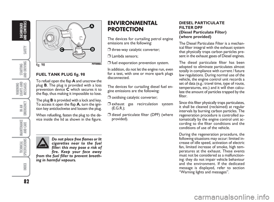
FUEL TANK PLUG fig. 98
To refuel open the flap Aand unscrew the
plug B. The plug is provided with a loss
prevention device Cwhich secures it to
the flap, thus making it impossible to lose.
The plug Bis provided with a lock and key.
To access it open the flap A, turn the igni-
tion key anticlockwise and loosen the plug.
When refuelling, fasten the plug to the de-
vice inside the lid as shown in the figure.
ENVIRONMENTAL
PROTECTION
The devices for curtailing petrol engine
emissions are the following:
❒three-way catalytic converter;
❒Lambda sensors;
❒fuel evaporation prevention system.
In addition, do not let the engine run, even
for a test, with one or more spark plugs
disconnected.
The devices for curtailing diesel fuel en-
gine emissions are the following:
❒oxidising catalytic converter;
❒exhaust gas recirculation system
(E.G.R.);
❒diesel particulate filter (DPF) (where
provided).
fig. 98
C
A
F0T0068m
Do not place free flames or lit
cigarettes near to the fuel
filler: this may pose a risk of
fire. Keep your face away
from the fuel filler to prevent breath-
ing in harmful vapours.
DIESEL PARTICULATE
FILTER DPF
(Diesel Particulate Filter)
(where provided)
The Diesel Particulate Filter is a mechan-
ical filter integral with the exhaust system
that physically traps carbon particles pre-
sent in the exhaust gases of Diesel engines.
The diesel particulate filter has been
adopted to eliminate particulates almost
totally in compliance with current / future
law regulations. During normal use of the
vehicle, the engine control unit records a
set of data (e.g.: travel time, type of route,
temperatures, etc.) and it will then calcu-
late the amount of particles trapped by the
filter.
Since this filter physically traps particulates,
it shall be cleaned (reclaimed) at regular
intervals by burning carbon particles. The
regeneration procedure is controlled au-
tomatically by the engine control unit ac-
cording to the filter conditions and the
conditions of use of the vehicle.
During the regeneration procedure, the
following situations may occur: limited in-
crease of idle speed, activation of electric
fan, limited increase of smoke, high tem-
peratures at the exhaust. These events
must not be considered as a malfunction-
ing: they do not impair vehicle behaviour
and the environment. If the dedicated
message is displayed, refer to section
“Warning lights and messages”.
036-082 Fiorino GB 2ed 13-02-2008 9:39 Pagina 82
Page 84 of 210
83
STARTING
AND DRIVING
WARNING
LIGHTS AND
MESSAGES
IN AN
EMERGENCY
MAINTENANCE
AND CARE
TECHNICAL
SPECIFICATIONS
INDEX
DASHBOARDAND CONTROLS
SAFETY
SEAT BELTS........................................................................... 84
S.B.R. SYSTEM....................................................................... 85
PRETENSIONERS................................................................ 86
CARRYING CHILDREN SAFELY..................................... 89
ISOFIX CHILD RESTRAINT ASSEMBLY SETUP .......... 93
FRONT AIRBAGS................................................................ 96
SIDE BAGS............................................................................. 98
S S
A A
F F
E E
T T
Y Y
083-100 Fiorino GB 2ed 8-02-2008 15:08 Pagina 83