FIAT FREEMONT 2011 Owner handbook (in English)
Manufacturer: FIAT, Model Year: 2011, Model line: FREEMONT, Model: FIAT FREEMONT 2011Pages: 267, PDF Size: 5.16 MB
Page 201 of 267
 3. Set the parking brake.
4. Place the shift lever in PARK.
5. Turn OFF the ignition.6. Block both the front and rear ofthe wheel diagonally opposite of
the jacking position. For example,
if changin")
3. Set the parking brake.
4. Place the shift lever in PARK.
5. Turn OFF the ignition.6. Block both the front and rear ofthe wheel diagonally opposite of
the jacking position. For example,
if changing the right front tire,
block the left rear wheel.
NOTE: Passengers should not remain in the vehicle
when the vehicle is being jacked.
Spare Tire Removal
NOTE: On seven-passenger models, fold the third-
row passenger seats flat. This will provide more space
when accessing the jacking tools and when operating
the winch mechanism.
1. Remove the jack-handle components 1, 2 and 3
from storage and assemble them. (fig. 144)
NOTE: Assemble components 2 and 3 by seating the
small ball at the end of component 2 in the small hole at
the end of component 3. This will lock these compo-
nents together. Assemble components 1 and 2 so that
the wheel nut socket at the end of component 1 faces
upward when seated on component 2. This will make it
easier to rotate the assembly when operating the
winch mechanism. 2. Fit the assembled jack-handle over the winch drive
nut located in the jack storage area. Rotate the
jack-handle assembly counterclockwise until the
spare tire is on the ground with enough cable slack
to allow you to pull the spare tire out from under-
neath the vehicle.
The winch mechanism is designed for use
with the jack-handle only. Use of an air
wrench or other power tools is not rec-
ommended and it can damage the winch.
3. Pull the spare tire out from underneath the vehicle and raise it upright so the tire's tread is on the
ground.
4. Tilt the retainer at the end of the winch cable and remove it from the center of the wheel. (fig. 145)
(fig. 144) Lowering/Raising Spare Tire
194
KNOWING
YOUR
VEHICLE
SAFETY
STARTING AND
DRIVING
WARNING
LIGHTS AND
MESSAGES
IN AN
EMERGENCY
SERVICING AND
CARETECHNICAL
SPECIFICATIONSCONTENTS
Page 202 of 267
Spare Tire Stowage
NOTE:Refer to “Spare Tire Removal” for informa-
tion on assembling the winch tools.
1. Place the spare tire near to the winch cable. Hold the spare upright so that the tire's tread is on the
ground and the valve stem is at the top of the wheel
facing away from the rear of the vehicle.
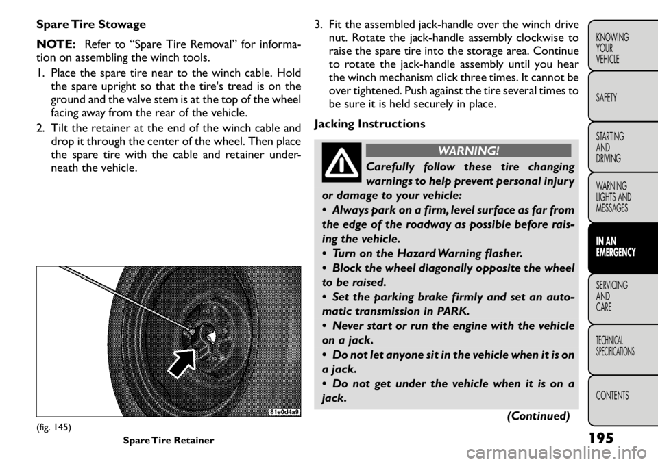
2. Tilt the retainer at the end of the winch cable and drop it through the center of the wheel. Then place
the spare tire with the cable and retainer under-
neath the vehicle. 3. Fit the assembled jack-handle over the winch drive
nut. Rotate the jack-handle assembly clockwise to
raise the spare tire into the storage area. Continue
to rotate the jack-handle assembly until you hear
the winch mechanism click three times. It cannot be
over tightened. Push against the tire several times to
be sure it is held securely in place.
Jacking Instructions
WARNING!
Carefully follow these tire changing
warnings to help prevent personal injury
or damage to your vehicle:
Always park on a firm, level surface as far from
the edge of the roadway as possible before rais-
ing the vehicle.
Turn on the Hazard Warning flasher.
Block the wheel diagonally opposite the wheel
to be raised.
Set the parking brake firmly and set an auto-
matic transmission in PARK.
Never start or run the engine with the vehicle
on a jack.
Do not let anyone sit in the vehicle when it is on
a jack.
Do not get under the vehicle when it is on a
jack.
(Continued)
(fig. 145)Spare Tire Retainer 195
KNOWING
YOURVEHICLE SAFETY
STARTING ANDDRIVING
WARNING
LIGHTS AND
MESSAGESIN AN
EMERGENCYSERVICING AND
CARETECHNICAL
SPECIFICATIONSCONTENTS
Page 203 of 267
 (Continued)
Only use the jack in the positions indicated and
for lifting this vehicle during a tire change.
If working on or near a roadway, be extremely
careful of motor traffic .
To assure")
(Continued)
Only use the jack in the positions indicated and
for lifting this vehicle during a tire change.
If working on or near a roadway, be extremely
careful of motor traffic .
To assure that spare tires, flat or inflated, are
securely stowed, spares must be stowed with the
valve stem facing the ground.
(fig. 146)
Do not attempt to raise the vehicle by
jacking on locations other than those
indicated in the Jacking Instructions for
this vehicle.
(fig. 147)
1. Remove the spare tire, jack, and jack-handle from stowage.
2. Loosen, but do not remove, the wheel nuts on the wheel with the flat tire. Turn the wheel nuts coun-
terclockwise one turn while the wheel is still on the
ground. 3. Place the jack underneath the lift area that is closest
to the flat tire. Center the jack saddle between the
drain flute formations on the sill flange. Turn the
jack screw clockwise to firmly engage the jack saddle
with the lift area of the sill flange. (fig. 148)
(fig. 149)
4. Raise the vehicle by turning the jack screw clock- wise with the jack handle. Raise the vehicle until the
tire just clears the road surface and enough clear-
ance is obtained to install the spare tire. Minimum
tire lift provides maximum stability.
WARNING!
Raising the vehicle higher than neces-
sary can make the vehicle less stable. It
could slip off the jack and hurt someone near it .
Raise the vehicle only enough to remove the tire.
(fig. 146) Jack Warning Label
(fig. 147) Jacking Locations
196
KNOWING
YOUR
VEHICLE
SAFETY
STARTING AND
DRIVING
WARNING
LIGHTS AND
MESSAGES
IN AN
EMERGENCY
SERVICING AND
CARETECHNICAL
SPECIFICATIONSCONTENTS
Page 204 of 267
 5. Remove the wheel nuts. For vehicles so equipped,remove the wheel cover from the wheel by hand.
Do not pry the wheel cover off. Then pull the wheel
off the hub.
WARNING!
To avoid possible personal")
5. Remove the wheel nuts. For vehicles so equipped,remove the wheel cover from the wheel by hand.
Do not pry the wheel cover off. Then pull the wheel
off the hub.
WARNING!
To avoid possible personal injury, handle
the wheel covers with care to avoid con-
tact with any sharp edges.
6. Install the spare tire.Be sure to mount the spare tire with the
valve stem facing outward. The vehicle
could be damaged if the spare tire is
mounted incorrectly.
(fig. 150)
NOTE:
• For vehicles so equipped, do not attempt to install a
center cap or wheel cover on the compact spare.
(fig. 148) Front Jacking Location(fig. 149) Rear Jacking Location
(fig. 150) Mounting Spare Tire 197
KNOWING
YOURVEHICLE SAFETY
STARTING ANDDRIVING
WARNING
LIGHTS AND
MESSAGESIN AN
EMERGENCYSERVICING AND
CARETECHNICAL
SPECIFICATIONSCONTENTS
Page 205 of 267
 • Refer to “Compact Spare Tire” and to “Limited-Use
Spare” under “Tires — General Information” in “Start-
ing and Operating” for additional warnings, cautions,
and information abo")
• Refer to “Compact Spare Tire” and to “Limited-Use
Spare” under “Tires — General Information” in “Start-
ing and Operating” for additional warnings, cautions,
and information about the spare tire, its use, andoperation.
7. Install the wheel nuts with the cone-shaped end ofthe nut toward the wheel. Lightly tighten the wheel
nuts.
WARNING!
To avoid the risk of forcing the vehicle
off the jack, do not tighten the wheel
nuts fully until the vehicle has been lowered.
Failure to follow this warning may result in per-
sonal injury.
8. Lower the vehicle by turning the jack screw coun- terclockwise with the jack handle.
9. Finish tightening the lug nuts. Push down on the wrench while at the end of the handle for increased
leverage. Tighten the lug nuts in a star pattern until
each nut has been tightened twice. The correct
tightness of each lug nut is 130 N
Page 206 of 267
 WARNING!
To avoid the risk of forcing the vehicle
off the jack, do not tighten the wheel
nuts fully until the vehicle has been lowered.
Failure to follow this warning may result in per-
sonal injury.")
WARNING!
To avoid the risk of forcing the vehicle
off the jack, do not tighten the wheel
nuts fully until the vehicle has been lowered.
Failure to follow this warning may result in per-
sonal injury.
(fig. 151)
3. Align the valve notch in the wheel cover with the valve stem on the wheel. Install the cover by hand,
snapping the cover over the two lug nuts. Do not
use a hammer or excessive force to install the cover. 4. Install the remaining lug nuts with the cone shaped
end of the nut toward the wheel. Lightly tighten the
lug nuts.
WARNING!
To avoid the risk of forcing the vehicle
off the jack, do not tighten the wheel
nuts fully until the vehicle has been lowered.
Failure to follow this warning may result in per-
sonal injury.
5. Lower the vehicle to the ground by turning the jack handle counterclockwise.
6. Finish tightening the lug nuts. Push down on the wrench while at the end of the handle for increased
leverage. Tighten the lug nuts in a star pattern until
each nut has been tightened twice. The correct
tightness of each lug nut is 130 N
Page 207 of 267
 WARNING!
To avoid the risk of forcing the vehicle
off the jack, do not tighten the wheel
nuts fully until the vehicle has been lowered.
Failure to follow this warning may result in per-
sonal injury.")
WARNING!
To avoid the risk of forcing the vehicle
off the jack, do not tighten the wheel
nuts fully until the vehicle has been lowered.
Failure to follow this warning may result in per-
sonal injury.
3. Lower the vehicle to the ground by turning the jack handle counterclockwise.
4. Finish tightening the lug nuts. Push down on the wrench while at the end of the handle for increased
leverage. Tighten the lug nuts in a star pattern until
each nut has been tightened twice. The correct
tightness of each lug nut is 130 N
Page 208 of 267
 BULB REPLACEMENT
LOW BEAM/HIGH BEAM/FRONT TURN
SIGNAL AND FRONT POSITION LAMP
1. Open the hood.
NOTE:It may be necessary to remove the air cleaner
filter housing and position the Totally Integrate")
BULB REPLACEMENT
LOW BEAM/HIGH BEAM/FRONT TURN
SIGNAL AND FRONT POSITION LAMP
1. Open the hood.
NOTE:It may be necessary to remove the air cleaner
filter housing and position the Totally Integrated Power
Module (TIPM) aside to replace certain lamps in the left
headlamp housing.
2. Rotate the applicable bulb and connector assembly
1∕4turn counterclockwise and remove the assembly
from the headlamp housing. (fig. 152)
3. Disconnect the bulb from the harness connector and then connect the replacement bulb.
Do not touch the new bulb with your
fingers. Oil contamination will severely
shorten bulb life. If the bulb comes in
contact with any oily surface, clean the bulb with
rubbing alcohol.
4. Install the bulb and connector assembly into the headlamp housing and rotate it
1∕4turn clockwise to
lock it in place.
FRONT FOG LAMP
NOTE: Turn the steering wheel to the right if replac-
ing the left front fog lamp or to the left if replacing the
right front fog lamp to allow for easier access to the
front of the wheel well.
1. Remove the fasteners retaining the front lower wheel well access panel and remove the access panel.
2. Remove the electrical connector from the fog lamp housing. (fig. 153)
3. Firmly grasp the bulb by the two side latches and squeeze them together to unlock the bulb from the
back of the front fog lamp housing.
4. Pull the bulb straight out from the keyed opening in the housing.
5. Align the index tabs of the replacement front fog lamp bulb with the slots in the collar of the bulb
opening on the back of the front fog lamp housing.
(fig. 152)
1 — Front Turn Signal Lamp Bulb
2 — Low Beam Headlamp Bulb
3 — Front Position Bulb
4 — High Beam Headlamp Bulb 201
KNOWING
YOURVEHICLE SAFETY
STARTING ANDDRIVING
WARNING
LIGHTS AND
MESSAGESIN AN
EMERGENCYSERVICING AND
CARETECHNICAL
SPECIFICATIONSCONTENTS
Page 209 of 267
 Do not touch the new bulb with your
fingers. Oil contamination will severely
shorten bulb life. If the bulb comes in
contact with an oily surface, clean the bulb with
rubbing alcohol.
6. Insert bulb")
Do not touch the new bulb with your
fingers. Oil contamination will severely
shorten bulb life. If the bulb comes in
contact with an oily surface, clean the bulb with
rubbing alcohol.
6. Insert bulb into the lamp housing until the index tabs are engaged in the slots of the collar.
7. Firmly and evenly push the bulb straight into the lamp housing until both side latches lock firmly into
place.
REAR FOG LAMP
1. Reach behind the bumper above the bumper rein- forcement and press the release tabs on the fog
lamp housing. (fig. 154)
2. Separate the fog lamp housing from the bumper fascia. 3. Disconnect the electrical harness connector.
(fig. 155)
(fig. 153)
(fig. 154) Release Tabs(fig. 155)Electrical Connector
202
KNOWING
YOUR
VEHICLE
SAFETY
STARTING AND
DRIVING
WARNING
LIGHTS AND
MESSAGES
IN AN
EMERGENCY
SERVICING AND
CARETECHNICAL
SPECIFICATIONSCONTENTS
Page 210 of 267
 4. Firmly grasp the bulb by the two side latches andsqueeze them together to unlock the bulb from the
back of the lamp housing.
5. Pull the bulb straight out from the keyed opening in the housing
6.")
4. Firmly grasp the bulb by the two side latches andsqueeze them together to unlock the bulb from the
back of the lamp housing.
5. Pull the bulb straight out from the keyed opening in the housing
6. Remove the bulb from the connector socket and install the replacement bulb.
7. Align the index tabs of the replacement rear fog lamp bulb/socket assembly with the slots in the
collar of the bulb opening on the back of the lamphousing.
8. Insert bulb into the lamp housing until the index tabs are engaged in the slots of the collar.
9. Firmly and evenly push the bulb straight into the lamp housing until both side latches lock firmly into
place.
10. Reinstall the fog lamp housing.
SIDE REPEATER LAMP
The side repeater lamps are located in both front
fender panels.
1. Push the side repeater lens to left side to release the spring tension and then pull it outward.
2. Disconnect the bulb from the harness connector and then connect the replacement bulb. (fig. 156)
3. Engage the right hook of the side repeater lamp into the sheet metal (note correct orientation of letter-
ing on lens).
4. Rotate the side repeater lamp in place until the left side engages (you will hear a light click). REAR TURN SIGNAL AND BACKUP LAMP
The taillamps are a two-piece design. The tail/stop/rear
turn signal lamps are located in the rear corner body
panels. The tail and backup lamps are located in the
liftgate.
Changing the Rear Turn Signal Lamp
1. Open the liftgate.
2. Remove the two fasteners from the inboard side of
the taillamp housing. (fig. 157)
3. Carefully insert a trim stick (plastic flat-blade tool) between the body panel and the outboard side of
the taillamp housing with one hand and grasp the
flange on the inboard side of the taillamp housing
with the other hand. Use the trim stick and hand
pressure together to disengage the taillamp housing
from the vehicle.
(fig. 156) Side Repeater Bulb Removal 203
KNOWING
YOURVEHICLE SAFETY
STARTING ANDDRIVING
WARNING
LIGHTS AND
MESSAGESIN AN
EMERGENCYSERVICING AND
CARETECHNICAL
SPECIFICATIONSCONTENTS