fuse FIAT FULLBACK 2017 Owner handbook (in English)
[x] Cancel search | Manufacturer: FIAT, Model Year: 2017, Model line: FULLBACK, Model: FIAT FULLBACK 2017Pages: 312, PDF Size: 12.31 MB
Page 73 of 312
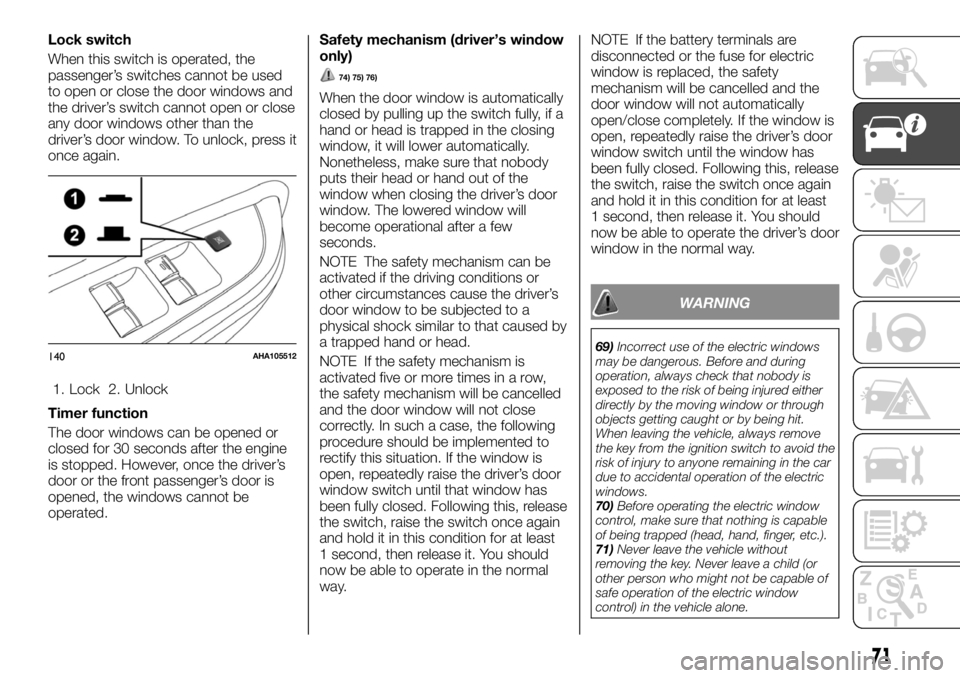
Lock switch
When this switch is operated, the
passenger’s switches cannot be used
to open or close the door windows and
the driver’s switch cannot open or close
any door windows other than the
driver’s door window. To unlock, press it
once again.
1. Lock 2. Unlock
Timer function
The door windows can be opened or
closed for 30 seconds after the engine
is stopped. However, once the driver’s
door or the front passenger’s door is
opened, the windows cannot be
operated.Safety mechanism (driver’s window
only)
74) 75) 76)
When the door window is automatically
closed by pulling up the switch fully, if a
hand or head is trapped in the closing
window, it will lower automatically.
Nonetheless, make sure that nobody
puts their head or hand out of the
window when closing the driver’s door
window. The lowered window will
become operational after a few
seconds.
NOTE The safety mechanism can be
activated if the driving conditions or
other circumstances cause the driver’s
door window to be subjected to a
physical shock similar to that caused by
a trapped hand or head.
NOTE If the safety mechanism is
activated five or more times in a row,
the safety mechanism will be cancelled
and the door window will not close
correctly. In such a case, the following
procedure should be implemented to
rectify this situation. If the window is
open, repeatedly raise the driver’s door
window switch until that window has
been fully closed. Following this, release
the switch, raise the switch once again
and hold it in this condition for at least
1 second, then release it. You should
now be able to operate in the normal
way.NOTE If the battery terminals are
disconnected or the fuse for electric
window is replaced, the safety
mechanism will be cancelled and the
door window will not automatically
open/close completely. If the window is
open, repeatedly raise the driver’s door
window switch until the window has
been fully closed. Following this, release
the switch, raise the switch once again
and hold it in this condition for at least
1 second, then release it. You should
now be able to operate the driver’s door
window in the normal way.
WARNING
69)Incorrect use of the electric windows
may be dangerous. Before and during
operation, always check that nobody is
exposed to the risk of being injured either
directly by the moving window or through
objects getting caught or by being hit.
When leaving the vehicle, always remove
the key from the ignition switch to avoid the
risk of injury to anyone remaining in the car
due to accidental operation of the electric
windows.
70)Before operating the electric window
control, make sure that nothing is capable
of being trapped (head, hand, finger, etc.).
71)Never leave the vehicle without
removing the key. Never leave a child (or
other person who might not be capable of
safe operation of the electric window
control) in the vehicle alone.140AHA105512
71
Page 74 of 312
72)A child may tamper with the switch at
the risk of its hands or head being trapped
in the window.
73)When driving with a child in the vehicle,
please press the window lock switch to
disable the passenger’s switches.
74)If the battery terminals are
disconnected or the fuse for electric
window is replaced, the safety mechanism
will be cancelled. If a hand or head got
trapped, a serious injury could result.
75)The safety mechanism is cancelled just
before the window is fully closed. This
allows the window to close completely.
Therefore be especially careful that no
fingers are trapped in the window.
76)The safety mechanism is deactivated
while the switch is pulled up. Therefore be
especially careful that fingers are not
trapped in the door window opening.CATALYTIC
CONVERTER
The exhaust gas scavenging devices
used with catalytic converter are
extremely efficient for the reduction of
noxious gases. The catalytic converter
is installed in the exhaust system.
It is important to keep the engine
properly tuned to ensure proper catalyst
operation and prevent possible catalyst
damage.
77)
NOTE Use fuel of the type
recommended in “Fuel selection”.
WARNING
77)As with any vehicle, do not park or
operate this vehicle in areas where
combustible materials such as dry grass or
leaves can come in contact with a hot
exhaust since a fire could occur.
DIESEL
PARTICULATE
FILTER (DPF)
(where provided)
The diesel particulate filter (DPF) is a
device that captures most of the
particulate matter (PM) in the exhaust
emissions of the diesel engine. The DPF
automatically burns away trapped PM
during vehicle operation. Under certain
driving conditions, however, the DPF is
not able to burn away all of the trapped
PM and, as a result, an excessive
amount of PM accumulates inside it.
78)
27)
NOTE To minimize the likelihood of
excessive accumulation of PM, try to
avoid driving for long periods at low
speeds and repeatedly driving short
distances and try to keep high engine
speed driving as much as possible.
NOTE The engine sounds slightly
different from usual while the DPF
automatically burns away trapped PM.
The change in the engine sound does
not indicate a fault.
DPF warning lamp
The DPF warning lamp comes on in the
event of an abnormality in the DPF
system.
72
GETTING TO KNOW YOUR VEHICLE
Page 163 of 312
Selector lever positions
“P” PARK
This position locks the transmission to
prevent the vehicle from moving. The
engine can be started in this position.
“R” REVERSE
This position is to back up.
112)
“N” NEUTRAL
At this position the transmission is
disengaged. It is the same as the
neutral position on a manual
transmission, and should only be used
when the vehicle is stationary for an
extended length of time during driving,
such as in a traffic jam.
113) 114) 115)
“D” DRIVE
This position is used for most city and
highway driving. The transmission will
automatically change its gear
depending on road and driving
conditions.
116)
Sport mode
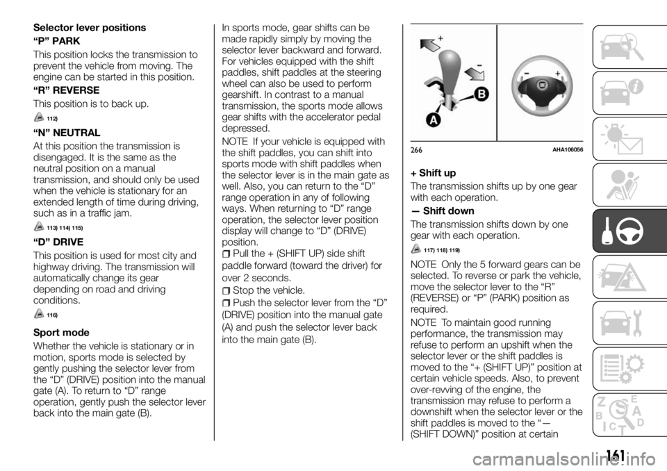
Whether the vehicle is stationary or in
motion, sports mode is selected by
gently pushing the selector lever from
the “D” (DRIVE) position into the manual
gate (A). To return to “D” range
operation, gently push the selector lever
back into the main gate (B).In sports mode, gear shifts can be
made rapidly simply by moving the
selector lever backward and forward.
For vehicles equipped with the shift
paddles, shift paddles at the steering
wheel can also be used to perform
gearshift. In contrast to a manual
transmission, the sports mode allows
gear shifts with the accelerator pedal
depressed.
NOTE If your vehicle is equipped with
the shift paddles, you can shift into
sports mode with shift paddles when
the selector lever is in the main gate as
well. Also, you can return to the “D”
range operation in any of following
ways. When returning to “D” range
operation, the selector lever position
display will change to “D” (DRIVE)
position.
Pull the + (SHIFT UP) side shift
paddle forward (toward the driver) for
over 2 seconds.
Stop the vehicle.
Push the selector lever from the “D”
(DRIVE) position into the manual gate
(A) and push the selector lever back
into the main gate (B).
+ Shift up
The transmission shifts up by one gear
with each operation.
— Shift down
The transmission shifts down by one
gear with each operation.
117) 118) 119)
NOTE Only the 5 forward gears can be
selected. To reverse or park the vehicle,
move the selector lever to the “R”
(REVERSE) or “P” (PARK) position as
required.
NOTE To maintain good running
performance, the transmission may
refuse to perform an upshift when the
selector lever or the shift paddles is
moved to the “+ (SHIFT UP)” position at
certain vehicle speeds. Also, to prevent
over-revving of the engine, the
transmission may refuse to perform a
downshift when the selector lever or the
shift paddles is moved to the “—
(SHIFT DOWN)” position at certain
266AHA106056
161
Page 164 of 312
vehicle speeds. When this happens, a
buzzer sounds to indicate that a
downshift is not going to take place.
NOTE Downward shifts are made
automatically when the vehicle slows
down. When the vehicle stops, 1st gear
is automatically selected.
NOTE When driving away on a slippery
road, push the selector lever forward
into the “+ (SHIFT UP)” position. This
cause the transmission to shift into the
2nd gear which is better for smooth
driving away on a slippery road. Push
the selector lever to the “— (SHIFT
DOWN)” side to shift back to the 1st
gear.
NOTE If the A/T fluid temperature is
high, the protection function operates.
In this case, the transmission may
refuse to perform an upshift when the
selector lever or the shift paddles are
operated to the “+ (SHIFT UP)” position
in sports mode, or it may automatically
downshift.
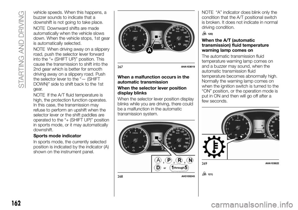
Sports mode indicator
In sports mode, the currently selected
position is indicated by the indicator (A)
shown on the instrument panel.When a malfunction occurs in the
automatic transmission
When the selector lever position
display blinks
When the selector lever position display
blinks while you are driving, there could
be a malfunction in the automatic
transmission system.NOTE “A” indicator does blink only the
condition that the A/T positional switch
is broken. It does not indicate in normal
driving condition.
120)
When the A/T (automatic
transmission) fluid temperature
warning lamp comes on
The automatic transmission fluid
temperature warning lamp comes on
and a buzzer may sound, when the
automatic transmission fluid
temperature becomes abnormally high.
Normally the warning lamp comes on
when the ignition switch is turned to the
“ON” position, or the operation mode is
put in ON and then will go off after a
few seconds.
121)
267AHA103619
268AH3100245
269AHA103622
162
STARTING AND DRIVING
Page 190 of 312
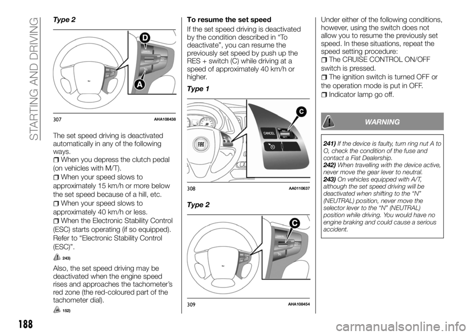
Type 2
The set speed driving is deactivated
automatically in any of the following
ways.
When you depress the clutch pedal
(on vehicles with M/T).
When your speed slows to
approximately 15 km/h or more below
the set speed because of a hill, etc.
When your speed slows to
approximately 40 km/h or less.
When the Electronic Stability Control
(ESC) starts operating (if so equipped).
Refer to “Electronic Stability Control
(ESC)”.
243)
Also, the set speed driving may be
deactivated when the engine speed
rises and approaches the tachometer’s
red zone (the red-coloured part of the
tachometer dial).
152)
To resume the set speed
If the set speed driving is deactivated
by the condition described in “To
deactivate”, you can resume the
previously set speed by push up the
RES + switch (C) while driving at a
speed of approximately 40 km/h or
higher.
Type 1
Type 2Under either of the following conditions,
however, using the switch does not
allow you to resume the previously set
speed. In these situations, repeat the
speed setting procedure:
The CRUISE CONTROL ON/OFF
switch is pressed.
The ignition switch is turned OFF or
the operation mode is put in OFF.
Indicator lamp go off.
WARNING
241)If the device is faulty, turn ring nut A to
O, check the condition of the fuse and
contact a Fiat Dealership.
242)When travelling with the device active,
never move the gear lever to neutral.
243)On vehicles equipped with A/T,
although the set speed driving will be
deactivated when shifting to the “N”
(NEUTRAL) position, never move the
selector lever to the “N” (NEUTRAL)
position while driving. You would have no
engine braking and could cause a serious
accident.
307AHA108438
308AA0110637
309AHA108454
188
STARTING AND DRIVING
Page 205 of 312
IN AN EMERGENCY
A punctured tyre or a burnt-out bulb?
At times, a problem may interfere with
our journey.
The pages on emergencies can help
you to deal with critical situations
independently and with calm.
In an emergency we recommend that
you call the freephone number found in
the Warranty Booklet.
It is also possible to call the
00 800 3428 0000 freephone number
to search the nearest Fiat Dealership.ERA GLONASS.............204
IF THE VEHICLE BREAKS DOWN. .208
EMERGENCY STARTING.......209
ENGINE OVERHEATING........210
BLEEDING THE FUEL SYSTEM . . .211
TOOLS, JACK AND JACK
HANDLE..................211
HOW TO CHANGE A TYRE.....216
TOWING..................223
OPERATION UNDER ADVERSE
DRIVING CONDITIONS........226
FUSIBLE LINKS.............227
FUSES...................227
REPLACEMENT OF LAMP BULBS .235
203
Page 229 of 312
Accumulation of ice on the braking
system can cause the wheels to lock.
Pull away from a standstill slowly after
confirming safety around the vehicle.
330)
On a bumpy or rutted road
Drive as slow as possible when driving
on bumpy or rutted roads.
178)
WARNING
330)Do not press the accelerator pedal
rapidly. If the wheels break free of the ice,
the vehicle could suddenly start moving
and possibly cause an accident.
IMPORTANT
178)The impact on tyres and/or wheels
when driving on a bumpy or rutted road
can damage the tyre and/or wheel.
FUSIBLE LINKS
The fusible links will melt to prevent a
fire if a large current attempts to flow
through certain electrical systems. In
case of a melted fuse link, we
recommend you to have your vehicle
inspected. For the fusible links, please
refer to “Passenger compartment fuse
location table” and “Engine
compartment fuse location table”.
331)
WARNING
331)Fusible links must not be replaced by
any other device. Failing to fit the correct
fusible may result in fire in the vehicle,
property destruction and serious or fatal
injuries at any time.
FUSES
Fuse block location
To prevent damage to the electrical
system due to short-circuiting or
overloading, each individual circuit is
provided with a fuse. There are fuse
blocks in the passenger compartment
and in the engine compartment.
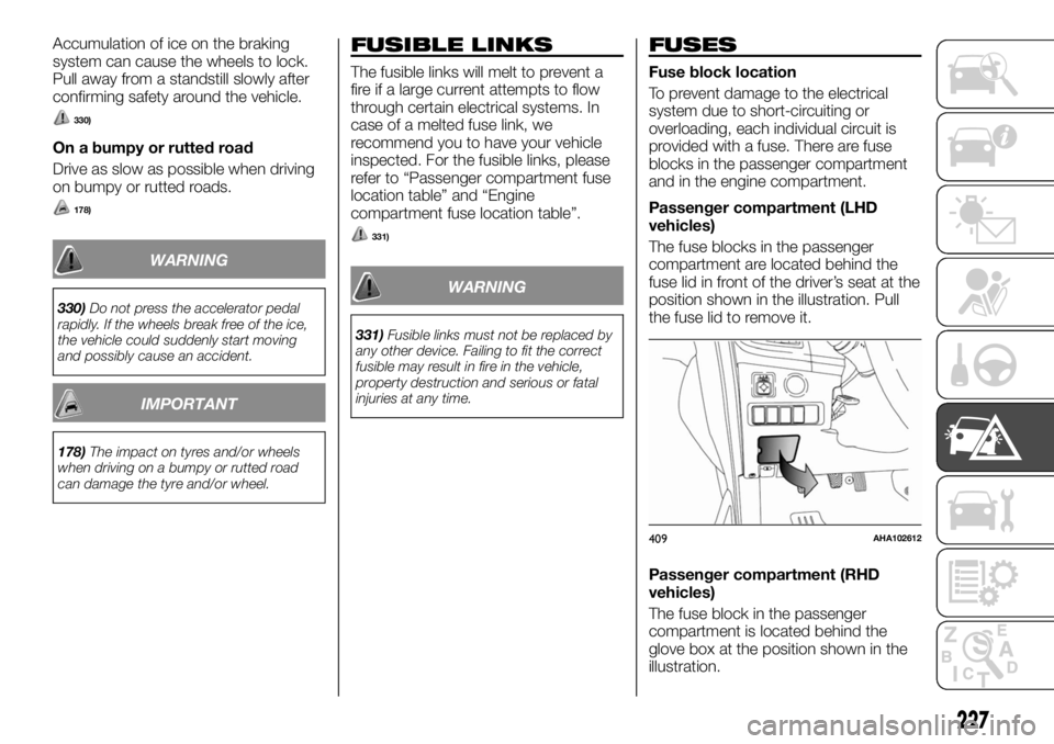
Passenger compartment (LHD
vehicles)
The fuse blocks in the passenger
compartment are located behind the
fuse lid in front of the driver’s seat at the
position shown in the illustration. Pull
the fuse lid to remove it.
Passenger compartment (RHD
vehicles)
The fuse block in the passenger
compartment is located behind the
glove box at the position shown in the
illustration.
409AHA102612
227
Page 230 of 312
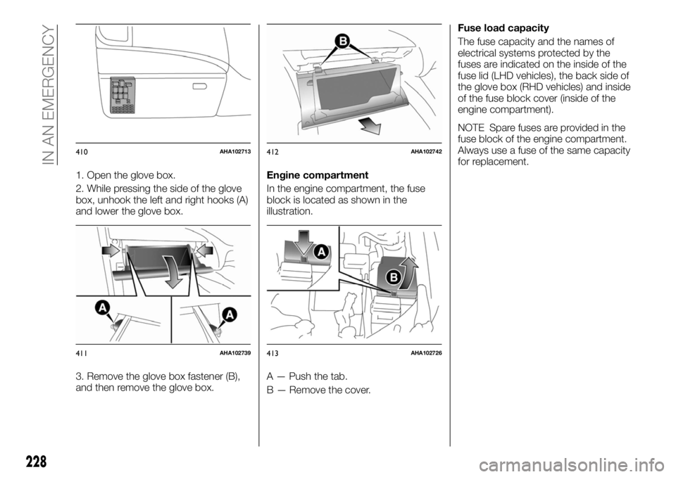
1. Open the glove box.
2. While pressing the side of the glove
box, unhook the left and right hooks (A)
and lower the glove box.
3. Remove the glove box fastener (B),
and then remove the glove box.Engine compartment
In the engine compartment, the fuse
block is located as shown in the
illustration.
A — Push the tab.
B — Remove the cover.Fuse load capacity
The fuse capacity and the names of
electrical systems protected by the
fuses are indicated on the inside of the
fuse lid (LHD vehicles), the back side of
the glove box (RHD vehicles) and inside
of the fuse block cover (inside of the
engine compartment).
NOTE Spare fuses are provided in the
fuse block of the engine compartment.
Always use a fuse of the same capacity
for replacement.
410AHA102713
411AHA102739
412AHA102742
413AHA102726
228
IN AN EMERGENCY
Page 231 of 312
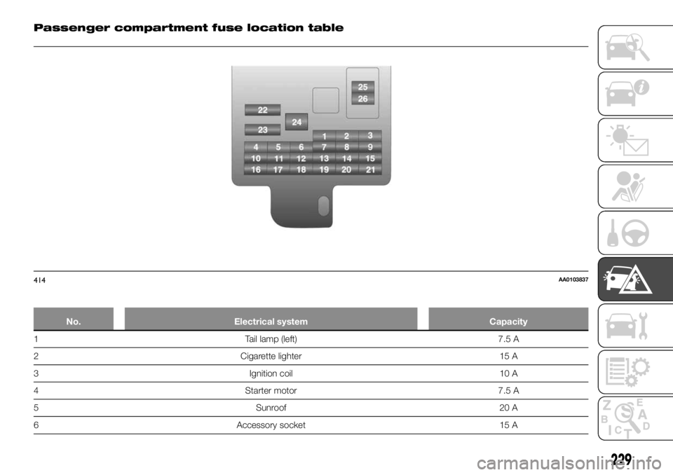
Passenger compartment fuse location table
No. Electrical system Capacity
1 Tail lamp (left) 7.5 A
2 Cigarette lighter 15 A
3 Ignition coil 10 A
4 Starter motor 7.5 A
5 Sunroof 20 A
6 Accessory socket 15 A
414AA0103837
229
Page 232 of 312
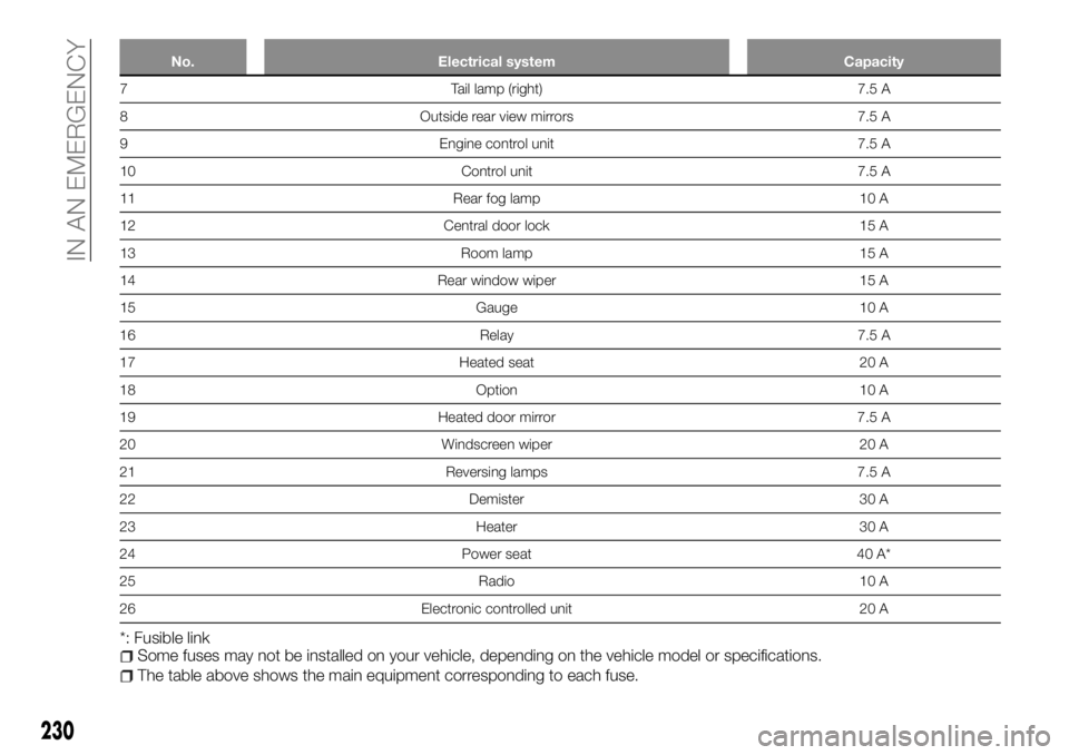
No. Electrical system Capacity
7 Tail lamp (right) 7.5 A
8 Outside rear view mirrors 7.5 A
9 Engine control unit 7.5 A
10 Control unit 7.5 A
11 Rear fog lamp 10 A
12 Central door lock 15 A
13 Room lamp 15 A
14 Rear window wiper 15 A
15 Gauge 10 A
16 Relay 7.5 A
17 Heated seat 20 A
18 Option 10 A
19 Heated door mirror 7.5 A
20 Windscreen wiper 20 A
21 Reversing lamps 7.5 A
22 Demister 30 A
23 Heater 30 A
24 Power seat 40 A*
25 Radio 10 A
26 Electronic controlled unit 20 A
*: Fusible linkSome fuses may not be installed on your vehicle, depending on the vehicle model or specifications.
The table above shows the main equipment corresponding to each fuse.
230
IN AN EMERGENCY