technical specifications FIAT IDEA 2010 1.G Owners Manual
[x] Cancel search | Manufacturer: FIAT, Model Year: 2010, Model line: IDEA, Model: FIAT IDEA 2010 1.GPages: 210, PDF Size: 4.4 MB
Page 145 of 210

144
STARTING
AND DRIVING
MAINTENANCE
AND CARE
TECHNICAL
SPECIFICATIONS
ALPHABETICAL
INDEX
DASHBOARD
AND
CONTROLS
SAFETY
WARNING
LIGHTS AND
MESSAGES
IN AN
EMERGENCY
WHEN NEEDING TO
CHANGE A BULB
GENERAL INSTRUCTIONS
❒When a bulb is not working, check
that the corresponding fuse is intact
before replacing it: refer to the “If a
fuse blows” paragraph in this chapter
for fuse location.
❒before changing a bulb check the con-
tacts for oxidation;
❒Burnt bulbs must be replaced by oth-
ers of the same type and power.
❒Always check the height of the head-
light beam after changing a bulb. Versions with alloy rims
❒Check that the hub contact surfaces
are clean;
❒fit the normal wheel centring it on the
pins, lead in the fastening screws and
tighten them using the wrench pro-
vided;
❒lower the car and remove the jack;
❒using the wrench provided, fully tight-
en the bolts in the sequence shown
in fig. 16.
❒snap fit the wheel cup on the hub.
When you have finished
❒stow the spare wheel C-fig. 11 in the
space provided in the boot;
❒Fit the jack partially open in its box B-
fig. 11forcing it lightly to prevent it
from vibrating when travelling;
❒put the tools back into their places in
the container;
❒arrange the container and tools in the
spare wheel and secure the fastening
device A-fig. 11;
❒rearrange the preformed boot cover
correctly.
Modifications or repairs to
the electrical system (elec-
tronic control units) that are not car-
ried out properly or do not take the
technical specifications of the system
into account can cause malfunctions
leading to the risk of fire.
WARNING
Halogen bulbs contain pres-
surised gas which may cause
small fragments of glass to be pro-
jected outwards if the bulb is broken.
WARNING
Halogen lamps must be han-
dled holding the metallic part
only. Touching the transpar-
ent part of the bulb with your
fingers may reduce the intensity of the
emitted light and even compromise du-
ration of the lamp itself. In the case of
accidental contact, rub the lamp with
a cloth and spirit and leave to dry.IMPORTANT When the weather is cold
or damp or after hard rain or after wash-
ing, the area of headlamps or rear lights,
may steam up and/or form drops of con-
densation on the inside. This is a natural
phenomenon due to the difference in tem-
perature and humidity between the inside
and the outside of the glass which does
not indicate a fault and does not compro-
mise the normal operation of lighting de-
vices. The mist disappears quickly turn-
ing the lights on, starting from the centre
of the diffuser, extending progressively to-
wards the edges.
133-160 LUM IDEA GB 2 ed.qxd 14-01-2010 13:50 Pagina 144
Page 146 of 210
145
STARTING
AND DRIVING
MAINTENANCE
AND CARE
TECHNICAL
SPECIFICATIONS
ALPHABETICAL
INDEX
DASHBOARD
AND
CONTROLS
SAFETY
WARNING
LIGHTS AND
MESSAGES
IN AN
EMERGENCY
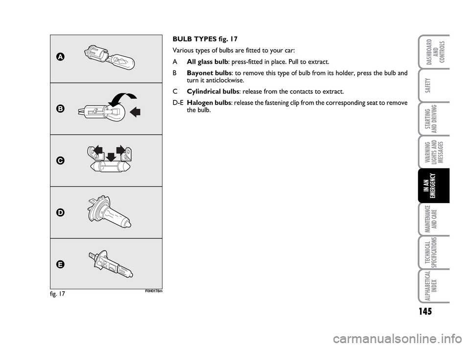
BULB TYPES fig. 17
Various types of bulbs are fitted to your car:
AAll glass bulb: press-fitted in place. Pull to extract.
BBayonet bulbs: to remove this type of bulb from its holder, press the bulb and
turn it anticlockwise.
CCylindrical bulbs: release from the contacts to extract.
D-EHalogen bulbs: release the fastening clip from the corresponding seat to remove
the bulb.
fig. 17F0H0178m
133-160 LUM IDEA GB 2 ed.qxd 14-01-2010 13:50 Pagina 145
Page 147 of 210
146
STARTING
AND DRIVING
MAINTENANCE
AND CARE
TECHNICAL
SPECIFICATIONS
ALPHABETICAL
INDEX
DASHBOARD
AND
CONTROLS
SAFETY
WARNING
LIGHTS AND
MESSAGES
IN AN
EMERGENCY
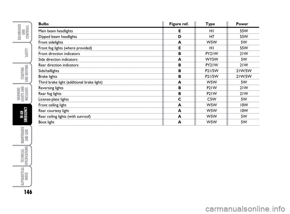
Bulbs Figure ref. Type Power
Main beam headlightsEH1 55W
Dipped beam headlights DH7 55W
Front sidelights AW5W 5W
Front fog lights (where provided)EH1 55W
Front direction indicators BPY21W 21W
Side direction indicators AWY5W 5W
Rear direction indicators BPY21W 21W
Side/taillights BP21/5W 21W/5W
Brake lights BP21/5W 21W/5W
Third brake light (additional brake light) AW5W 5W
Reversing lights BP21W 21W
Rear fog lights BP21W 21W
License-plate lights CC5W 5W
Front ceiling lightAW5W 10W
Rear courtesy lightAW5W 10W
Rear ceiling lights (with sunroof)AW5W 5W
Boot light AW5W 5W
133-160 LUM IDEA GB 2 ed.qxd 14-01-2010 13:50 Pagina 146
Page 148 of 210
147
STARTING
AND DRIVING
MAINTENANCE
AND CARE
TECHNICAL
SPECIFICATIONS
ALPHABETICAL
INDEX
DASHBOARD
AND
CONTROLS
SAFETY
WARNING
LIGHTS AND
MESSAGES
IN AN
EMERGENCY
REPLACING EXTERIOR
BULBS
For the type of bulb and power rating, see
“When needing to change a bulb”.
FRONT LIGHT CLUSTER
The front light clusters contain side lights,
dipped beam, main beam and direction in-
dicator bulbs.
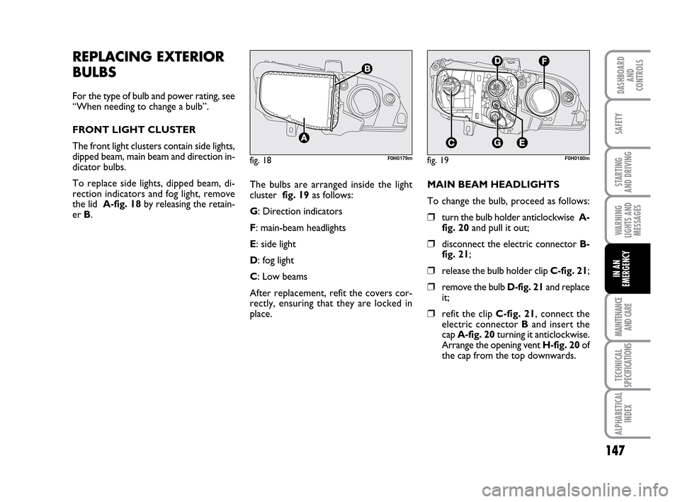
To replace side lights, dipped beam, di-
rection indicators and fog light, remove
the lid A-fig. 18by releasing the retain-
er B.
fig. 18F0H0179mfig. 19F0H0180m
The bulbs are arranged inside the light
cluster fig. 19as follows:
G: Direction indicators
F: main-beam headlights
E: side light
D: fog light
C: Low beams
After replacement, refit the covers cor-
rectly, ensuring that they are locked in
place.MAIN BEAM HEADLIGHTS
To change the bulb, proceed as follows:
❒turn the bulb holder anticlockwise A-
fig. 20and pull it out;
❒disconnect the electric connector B-
fig. 21;
❒release the bulb holder clip C-fig. 21;
❒remove the bulb D-fig. 21and replace
it;
❒refit the clip C-fig. 21, connect the
electric connector Band insert the
cap A-fig. 20turning it anticlockwise.
Arrange the opening vent H-fig. 20of
the cap from the top downwards.
133-160 LUM IDEA GB 2 ed.qxd 14-01-2010 13:50 Pagina 147
Page 149 of 210
148
STARTING
AND DRIVING
MAINTENANCE
AND CARE
TECHNICAL
SPECIFICATIONS
ALPHABETICAL
INDEX
DASHBOARD
AND
CONTROLS
SAFETY
WARNING
LIGHTS AND
MESSAGES
IN AN
EMERGENCY
fig. 20F0H0181mfig. 21
C
B
D
F0H0214m
fig. 22F0H0182m
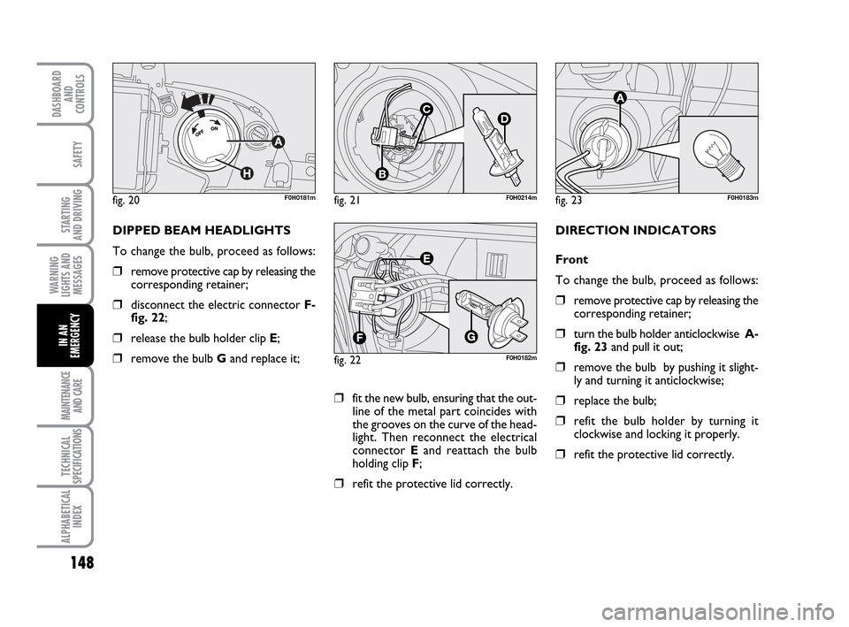
DIPPED BEAM HEADLIGHTS
To change the bulb, proceed as follows:
❒remove protective cap by releasing the
corresponding retainer;
❒disconnect the electric connector F-
fig. 22;
❒release the bulb holder clip E;
❒remove the bulb Gand replace it;
fig. 23F0H0183m
DIRECTION INDICATORS
Front
To change the bulb, proceed as follows:
❒remove protective cap by releasing the
corresponding retainer;
❒turn the bulb holder anticlockwise A-
fig. 23and pull it out;
❒remove the bulb by pushing it slight-
ly and turning it anticlockwise;
❒replace the bulb;
❒refit the bulb holder by turning it
clockwise and locking it properly.
❒refit the protective lid correctly.
❒fit the new bulb, ensuring that the out-
line of the metal part coincides with
the grooves on the curve of the head-
light. Then reconnect the electrical
connector Eand reattach the bulb
holding clip F;
❒refit the protective lid correctly.
133-160 LUM IDEA GB 2 ed.qxd 14-01-2010 13:50 Pagina 148
Page 150 of 210
149
STARTING
AND DRIVING
MAINTENANCE
AND CARE
TECHNICAL
SPECIFICATIONS
ALPHABETICAL
INDEX
DASHBOARD
AND
CONTROLS
SAFETY
WARNING
LIGHTS AND
MESSAGES
IN AN
EMERGENCY
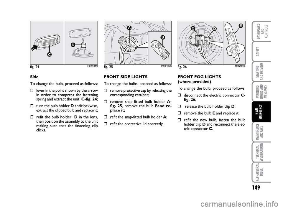
Side
To change the bulb, proceed as follows:
❒lever in the point shown by the arrow
in order to compress the fastening
spring and extract the unit C-fig. 24;
❒turn the bulb holder Danticlockwise,
extract the clipped bulb and replace it;
❒refit the bulb holder Din the lens,
then position the assembly to the unit
making sure that the fastening clip
clicks.
fig. 24F0H0184m
FRONT SIDE LIGHTS
To change the bulbs, proceed as follows:
❒remove protective cap by releasing the
corresponding retainer;
❒remove snap-fitted bulb holder A-
fig. 25, remove the bulb Band re-
place it;
❒refit the snap-fitted bulb holder A;
❒refit the protective lid correctly.FRONT FOG LIGHTS
(where provided)
To change the bulb, proceed as follows:
❒disconnect the electric connector C-
fig. 26;
❒release the bulb holder clip D;
❒remove the bulb Eand replace it;
❒refit the new bulb, fasten the bulb
holder clip Dand reconnect the elec-
tric connector C.
fig. 25F0H0185mfig. 26F0H0186m
133-160 LUM IDEA GB 2 ed.qxd 14-01-2010 13:50 Pagina 149
Page 151 of 210
150
STARTING
AND DRIVING
MAINTENANCE
AND CARE
TECHNICAL
SPECIFICATIONS
ALPHABETICAL
INDEX
DASHBOARD
AND
CONTROLS
SAFETY
WARNING
LIGHTS AND
MESSAGES
IN AN
EMERGENCY
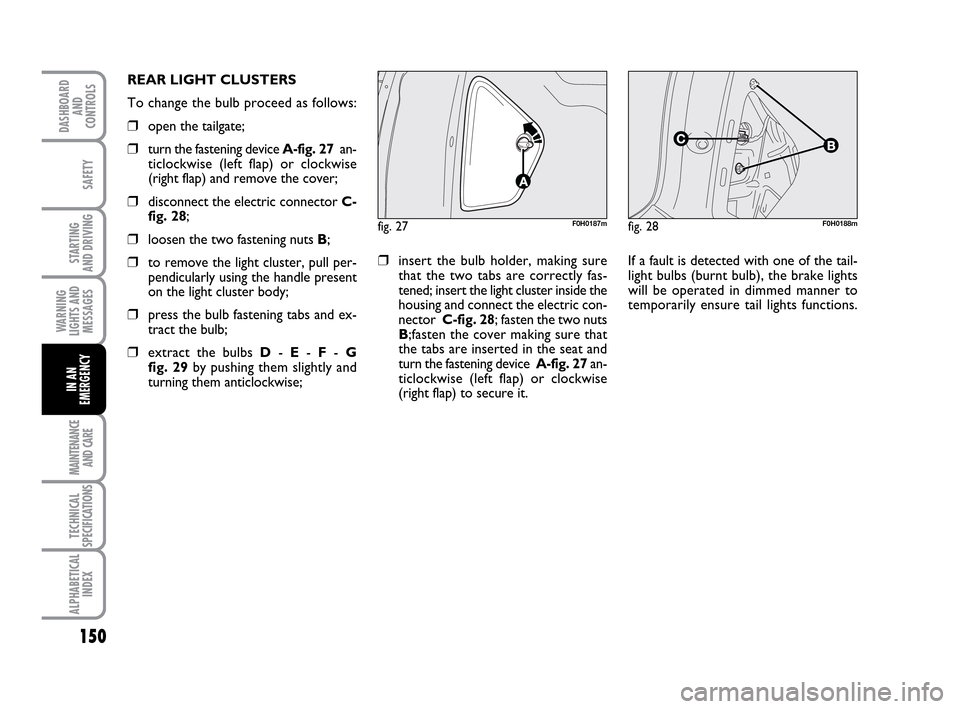
fig. 27F0H0187mfig. 28F0H0188m
REAR LIGHT CLUSTERS
To change the bulb proceed as follows:
❒open the tailgate;
❒turn the fastening device A-fig. 27an-
ticlockwise (left flap) or clockwise
(right flap) and remove the cover;
❒disconnect the electric connector C-
fig. 28;
❒loosen the two fastening nuts B;
❒to remove the light cluster, pull per-
pendicularly using the handle present
on the light cluster body;
❒press the bulb fastening tabs and ex-
tract the bulb;
❒extract the bulbs D- E- F- G
fig. 29by pushing them slightly and
turning them anticlockwise;
❒insert the bulb holder, making sure
that the two tabs are correctly fas-
tened; insert the light cluster inside the
housing and connect the electric con-
nector C-fig. 28; fasten the two nuts
B;fasten the cover making sure that
the tabs are inserted in the seat and
turn the fastening device A-fig. 27an-
ticlockwise (left flap) or clockwise
(right flap) to secure it. If a fault is detected with one of the tail-
light bulbs (burnt bulb), the brake lights
will be operated in dimmed manner to
temporarily ensure tail lights functions.
133-160 LUM IDEA GB 2 ed.qxd 14-01-2010 13:50 Pagina 150
Page 152 of 210
151
STARTING
AND DRIVING
MAINTENANCE
AND CARE
TECHNICAL
SPECIFICATIONS
ALPHABETICAL
INDEX
DASHBOARD
AND
CONTROLS
SAFETY
WARNING
LIGHTS AND
MESSAGES
IN AN
EMERGENCY
The tail lights will resume normal opera-
tion when the burnt bulb is replaced.
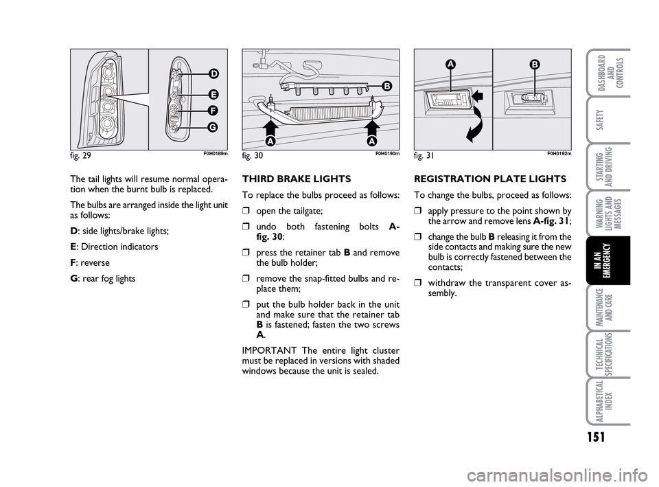
The bulbs are arranged inside the light unit
as follows:
D: side lights/brake lights;
E: Direction indicators
F: reverse
G: rear fog lights
fig. 29F0H0189mfig. 30F0H0190m
THIRD BRAKE LIGHTS
To replace the bulbs proceed as follows:
❒open the tailgate;
❒undo both fastening bolts A-
fig. 30:
❒press the retainer tab Band remove
the bulb holder;
❒remove the snap-fitted bulbs and re-
place them;
❒put the bulb holder back in the unit
and make sure that the retainer tab
Bis fastened; fasten the two screws
A.
IMPORTANT The entire light cluster
must be replaced in versions with shaded
windows because the unit is sealed.REGISTRATION PLATE LIGHTS
To change the bulbs, proceed as follows:
❒apply pressure to the point shown by
the arrow and remove lens A-fig. 31;
❒change the bulb B releasing it from the
side contacts and making sure the new
bulb is correctly fastened between the
contacts;
❒withdraw the transparent cover as-
sembly.
fig. 31F0H0192m
133-160 LUM IDEA GB 2 ed.qxd 14-01-2010 13:50 Pagina 151
Page 153 of 210
152
STARTING
AND DRIVING
MAINTENANCE
AND CARE
TECHNICAL
SPECIFICATIONS
ALPHABETICAL
INDEX
DASHBOARD
AND
CONTROLS
SAFETY
WARNING
LIGHTS AND
MESSAGES
IN AN
EMERGENCY
REPLACING AN
INTERIOR BULB
For the type of bulb and power rating, see
“When needing to change a bulb”.
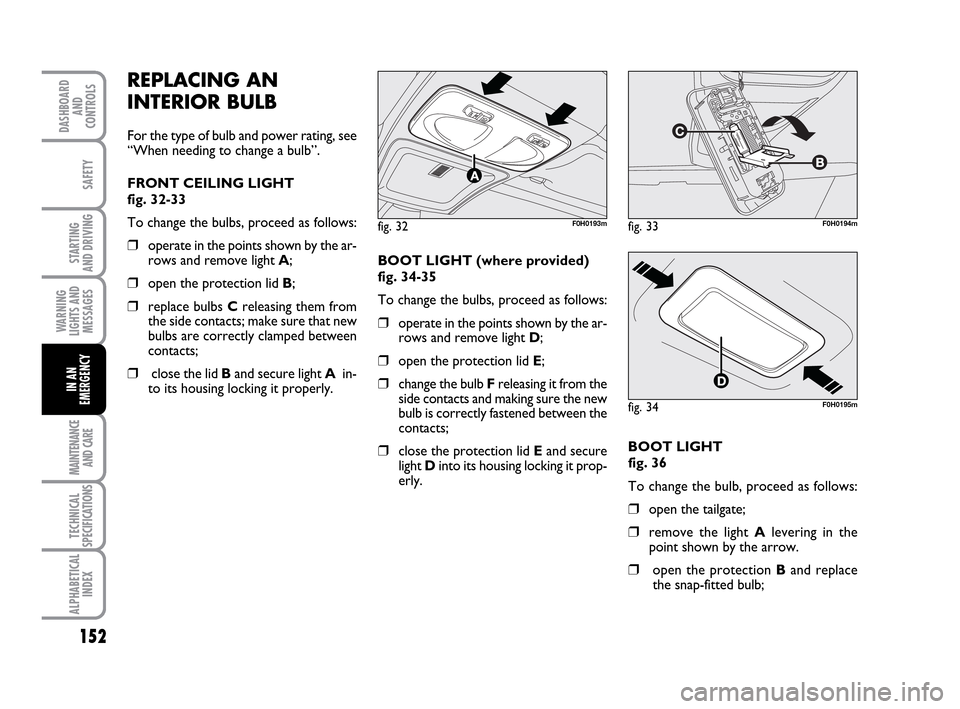
FRONT CEILING LIGHT
fig. 32-33
To change the bulbs, proceed as follows:
❒operate in the points shown by the ar-
rows and remove light A;
❒open the protection lid B;
❒replace bulbs Creleasing them from
the side contacts; make sure that new
bulbs are correctly clamped between
contacts;
❒close the lid Band secure light Ain-
to its housing locking it properly. BOOT LIGHT (where provided)
fig. 34-35
To change the bulbs, proceed as follows:
❒operate in the points shown by the ar-
rows and remove light D;
❒open the protection lid E;
❒change the bulb F releasing it from the
side contacts and making sure the new
bulb is correctly fastened between the
contacts;
❒close the protection lid Eand secure
light Dinto its housing locking it prop-
erly.
fig. 32F0H0193mfig. 33F0H0194m
fig. 34F0H0195m
BOOT LIGHT
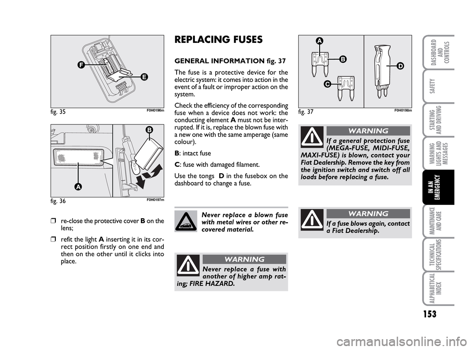
fig. 36
To change the bulb, proceed as follows:
❒open the tailgate;
❒remove the light Alevering in the
point shown by the arrow.
❒open the protection Band replace
the snap-fitted bulb;
133-160 LUM IDEA GB 2 ed.qxd 14-01-2010 13:50 Pagina 152
Page 154 of 210
153
STARTING
AND DRIVING
MAINTENANCE
AND CARE
TECHNICAL
SPECIFICATIONS
ALPHABETICAL
INDEX
DASHBOARD
AND
CONTROLS
SAFETY
WARNING
LIGHTS AND
MESSAGES
IN AN
EMERGENCY
❒re-close the protective cover Bon the
lens;
❒refit the light Ainserting it in its cor-
rect position firstly on one end and
then on the other until it clicks into
place.
fig. 35F0H0196m
fig. 36F0H0197m
REPLACING FUSES
GENERAL INFORMATION fig. 37
The fuse is a protective device for the
electric system: it comes into action in the
event of a fault or improper action on the
system.
Check the efficiency of the corresponding
fuse when a device does not work: the
conducting element Amust not be inter-
rupted. If it is, replace the blown fuse with
a new one with the same amperage (same
colour).
B: intact fuse
C: fuse with damaged filament.
Use the tongs Din the fusebox on the
dashboard to change a fuse.
fig. 37F0H0198m
Never replace a blown fuse
with metal wires or other re-
covered material.
Never replace a fuse with
another of higher amp rat-
ing; FIRE HAZARD.
WARNING
If a general protection fuse
(MEGA-FUSE, MIDI-FUSE,
MAXI-FUSE) is blown, contact your
Fiat Dealership. Remove the key from
the ignition switch and switch off all
loads before replacing a fuse.
WARNING
If a fuse blows again, contact
a Fiat Dealership.
WARNING
133-160 LUM IDEA GB 2 ed.qxd 14-01-2010 13:50 Pagina 153