technical specifications FIAT PANDA 2009 169 / 2.G Owners Manual
[x] Cancel search | Manufacturer: FIAT, Model Year: 2009, Model line: PANDA, Model: FIAT PANDA 2009 169 / 2.GPages: 226, PDF Size: 5.29 MB
Page 134 of 226
133KNOW
YOUR VEHICLE
SAFETY
CORRECT USE
OF THE CARWARNING LIGHTS
AND MESSAGESIN
AN EMERGENCY
CAR
MAINTENANCE
TECHNICAL
SPECIFICATIONS
INDEX
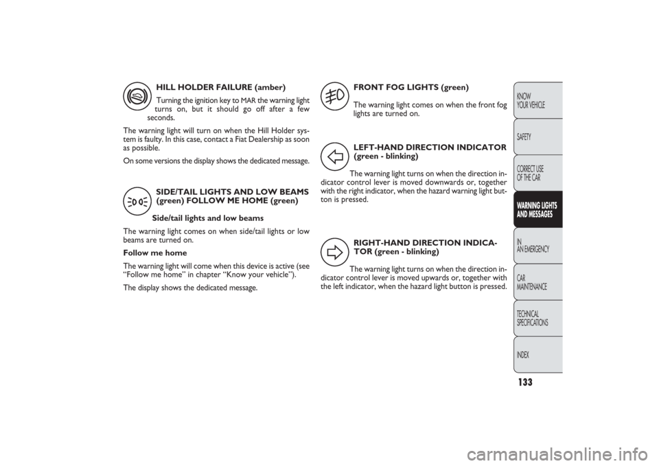
FRONT FOG LIGHTS (green)
The warning light comes on when the front fog
lights are turned on. HILL HOLDER FAILURE (amber)
Turning the ignition key to
MAR
the warning light
turns on, but it should go off after a few
seconds.
The warning light will turn on when the Hill Holder sys-
tem is faulty. In this case, contact a Fiat Dealership as soon
as possible.
On some versions the display shows the dedicated message.
SIDE/TAIL LIGHTS AND LOW BEAMS
(green) FOLLOW ME HOME (green)
Side/tail lights and low beams
The warning light comes on when side/tail lights or low
beams are turned on.
Follow me home
The warning light will come when this device is active (see
“Follow me home” in chapter “Know your vehicle”).
The display shows the dedicated message.
*3
LEFT-HAND DIRECTION INDICATOR
(green - blinking)
The warning light turns on when the direction in-
dicator control lever is moved downwards or, together
with the right indicator, when the hazard warning light but-
ton is pressed.
RIGHT-HAND DIRECTION INDICA-
TOR (green - blinking)
The warning light turns on when the direction in-
dicator control lever is moved upwards or, together with
the left indicator, when the hazard light button is pressed.
5FD
123-134 PANDA EN 7-10-2009 13:49 Pagina 133
Page 135 of 226
134
KNOW YOUR
VEHICLE
SAFETY
CORRECT USE
OF THE CAR
WARNING LIGHTS
AND MESSAGES
IN
AN EMERGENCY
CAR
MAINTENANCE
TECHNICAL
SPECIFICATIONS
INDEX
LIMITED RANGE (versions with reconfigurable
multifunction display)
The display will show the dedicated message to warn the
driver that the driving range is less than 50 km.
ASR SYSTEM (versions with reconfigurable mul-
tifunction display)
The ASR system can be turned off by pressing the button
ASR OFF.
The display will show the dedicated message to warn the
driver that the system is off; at the same time the button
LED will come on.
Pressing again the button ASR OFF, the button LED will
turn off and the display will show the dedicated message
to warn the driver that the system is on again. POSSIBLE PRESENCE OF ICE ON THE ROAD
(versions with reconfigurable multifunction
display)
When the outside temperature reaches or falls below
3 °C the outside temperature indication flashes to warn
the driver about the possible presence of ice on the road.
The display shows the dedicated message.
SPEED LIMIT EXCEEDED
The display will show the dedicated message when the car
exceeds the set speed limit (see “Multifunction Display” in
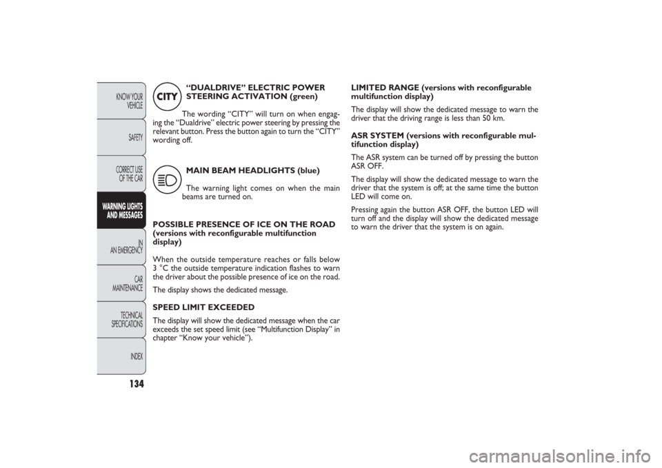
chapter “Know your vehicle”).“DUALDRIVE” ELECTRIC POWER
STEERING ACTIVATION (green)
The wording “CITY” will turn on when engag-
ing the “Dualdrive” electric power steering by pressing the
relevant button. Press the button again to turn the “CITY”
wording off.
MAIN BEAM HEADLIGHTS (blue)
The warning light comes on when the main
beams are turned on.
CITY1
123-134 PANDA EN 7-10-2009 13:49 Pagina 134
Page 136 of 226
135KNOW
YOUR VEHICLE
SAFETY
WARNING LIGHTS
AND MESSAGESIN
AN EMERGENCYCAR
MAINTENANCE
TECHNICAL
SPECIFICATIONS
INDEX
IN AN EMERGENCY
STARTING THE ENGINEEMERGENCY START-UP
If the Fiat CODE system fails to deactivate engine immo-
bilising system the instrument panel warning lights
Y
and
U
stay on and the engine cannot be started.
To start the engine the emergency start-up can be per-
formed.
Read the whole procedure carefully before trying to car-
ry it out: if you make a mistake, you need to turn the ig-
nition key back to STOP and repeat the whole operation
from the beginning.
Proceed as follows:
❒
read the five-digit electronic code from the CODE card;
❒
turn the ignition key to MAR;
❒
press and hold down the accelerator pedal: the warn-
ing light
U
turns on for about 8 seconds, and then goes
off;
❒
release the accelerator pedal and count the flashes of
the warning light
U
;
❒
count the number of flashes that corresponds to the
first digit of the code on the CODE card, then press the
accelerator pedal and hold it there until the warning
light
U
comes on (for 4 seconds) and then goes off. Re-
lease the accelerator pedal;
CORRECT USE
OF THE CAR
❒
the warning light
U
will start flashing again: after it has
flashed the number of times corresponding to the
second digit on the CODE card, fully depress the ac-
celerator pedal and hold it there;
❒
do the same for the remaining digits on the CODE card;
❒
once the last digit has been entered, hold the acceler-
ator pedal pressed. The warning light
U
will light up for
four seconds and then go out. Release the accelerator
pedal;
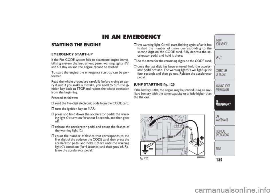
JUMP STARTING fig. 120
If the battery is flat, the engine may be started using an aux-
iliary battery with the same capacity or a little higher than
the flat one.
F0Z0694m
fig. 120
135-168 PANDA EN 7-10-2009 14:06 Pagina 135
Page 137 of 226
136KNOW
YOUR VEHICLE
SAFETY
CORRECT USE
OF THE CAR
WARNING LIGHTS
AND MESSAGES
IN
AN EMERGENCYCAR
MAINTENANCE
TECHNICAL
SPECIFICATIONS
INDEX
Never use a fast battery-charger to start the
engine as this could damage the electron-
ic systems of your car, particularly the ig-
nition and fuel supply control units.This procedure must be performed by qual-
ified personnel as incorrect actions may
cause high-intensity electrical discharge. Further-
more, battery fluid is poisonous and corrosive: avoid
contact with your skin and eyes. Keep naked flames
away from the battery. No smoking. Do not cause
sparks.
WARNING
If after a few attempts the engine does not start, do not
insist rather contact the nearest Fiat Dealership.
IMPORTANT Do not directly connect the negative ter-
minals of the two batteries: any sparks may ignite the det-
onating gas which could come out of the battery. If the aux-
iliary battery is installed on another car, prevent any contact
between metal parts of the cars and the flat battery.
BUMP STARTING
Never bump start the engine by pushing, towing or driving
downhill.
This could cause a flow of fuel into the catalytic convert-
er and damage it beyond repair.
IMPORTANT Remember that the servo-brake and elec-
trical power steering system (for versions/markets where
provided) are not operating until the engine is started, a
greater effort will therefore be required to press the brake
pedal or turn the steering wheel. Proceed as follows to start the car:
❒
connect the positive terminals (+ sign close to the ter-
minal) of both batteries using a lead;
❒
with a second lead, connect the negative terminal − of
the auxiliary battery to an earthing point
E
on the en-
gine or the gearbox of the car to be started;
❒
start the engine;
❒
when the engine has been started, follow the sequence
above in reverse order to remove the leads.
135-168 PANDA EN 7-10-2009 14:06 Pagina 136
Page 138 of 226
137KNOW
YOUR VEHICLE
SAFETY
CORRECT USE
OF THE CAR
WARNING LIGHTS
AND MESSAGESIN
AN EMERGENCYCAR
MAINTENANCE
TECHNICAL
SPECIFICATIONS
INDEX
REPLACING A WHEELGENERAL INSTRUCTIONS
The car can be delivered (upon request/where provided)
with standard spare wheel or space-saver wheel; see
changing instructions on the following paragraphs. Wheel
changing and correct use of the jack and spare wheel call
for some precautions as listed below.
The space-saver wheel (where provided) is
specific to your car, do not use it on other
models, nor use the spare wheel of other models
on your car. The space-saver wheel must only be
used in case of emergency. It shall only be used for
the distance necessary to reach a service point and
the car speed shall not exceed 80 km/h. The spare
wheel has an orange sticker that summarises the
main cautions for use and limitations. The sticker
should never be removed or covered. Never apply
a wheel cup on a space-saver wheel. The sticker
gives the following information in four languages:
Caution! For temporary use only! 80 km/h max.!
Replace by standard wheel as soon as possible. Do
not cover this label in use. If you change the type
of wheel (alloy rims instead of steel rims) you will
have to change the entire set of fastening bolts with
another set of suitably sized bolts.
WARNING
Alert other drivers that the car is station-
ary in compliance with local regulations:
hazard warning lights, warning triangle, etc. Any
passengers on board should leave the car, espe-
cially if it is heavily laden. Passengers should stay
away from on-coming traffic while the wheel is
being changed. If parked on a slope or rough sur-
face, chock the wheels with wedges or other suit-
able devices.
WARNING
The driving features of the car may change
when a space-saver wheel is fitted. Avoid
sudden acceleration and braking, sudden steering
and fast cornering. The total life of a space-saver
wheel is approximately 3000 km, after which it
must be replaced by another wheel of the same
type. Never attempt to fit a conventional tyre on
a rim designed for use as a space-saver wheel.
Have the punctured wheel repaired and replaced
as soon as possible. Two or more space-saver
wheels should never be used together. Do not
grease the threads of bolts before installing them:
they might slip out.
WARNING
135-168 PANDA EN 7-10-2009 14:06 Pagina 137
Page 139 of 226
138KNOW
YOUR VEHICLE
SAFETY
CORRECT USE
OF THE CAR
WARNING LIGHTS
AND MESSAGES
IN
AN EMERGENCYCAR
MAINTENANCE
TECHNICAL
SPECIFICATIONS
INDEX
F0Z0171m
fig. 121
Please note that:❒
the jack weights 1.76 kg;
❒
the jack requires no adjustment;
❒
the jack cannot be repaired. If it breaks it must be re-
placed with a new jack;
❒
no tool other than its cranking device may be fitted on
the jack.
To change a wheel proceed as follows:
❒
stop the car in a position so that it is not a danger for
on-coming traffic and where you can replace the wheel
safely. The ground must be flat and compact;
❒
turn the engine off and pull up the handbrake.
❒
engage the first gear or reverse;
❒
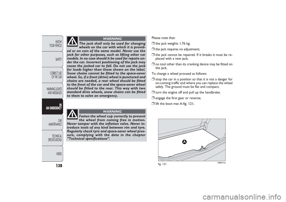
lift the boot mat A-fig. 121;
Fasten the wheel cup correctly to prevent
the wheel from coming free in motion.
Never tamper with the inflation valve. Never in-
troduce tools of any kind between rim and tyre.
Regularly check tyre and space-saver wheel pres-
sure, complying with the data in the chapter
“Technical specifications”.
WARNING
The jack shall only be used for changing
wheels on the car with which it is provid-
ed or on cars of the same model. Never use the
jack for other purposes, such as lifting other car
models. In no case should it be used for repairs un-
der the car. Incorrect positioning of the jack may
cause the jacked car to fall. Do not use the jack
for loads higher than those shown on the label.
Snow chains cannot be fitted to the space-saver
wheel. So, if a front (drive) wheel is punctured and
chains are needed, a rear wheel should be fitted
to the front of the car and the space-saver wheel
should be fitted to the rear. This way with two
standard drive wheels, snow chains can be fitted
to them to solve an emergency.
WARNING
135-168 PANDA EN 7-10-2009 14:06 Pagina 138
Page 140 of 226
139KNOW
YOUR VEHICLE
SAFETY
CORRECT USE
OF THE CAR
WARNING LIGHTS
AND MESSAGESIN
AN EMERGENCYCAR
MAINTENANCE
TECHNICAL
SPECIFICATIONS
INDEX
F0Z0078m
fig. 122
F0Z0695m
fig. 123
❒
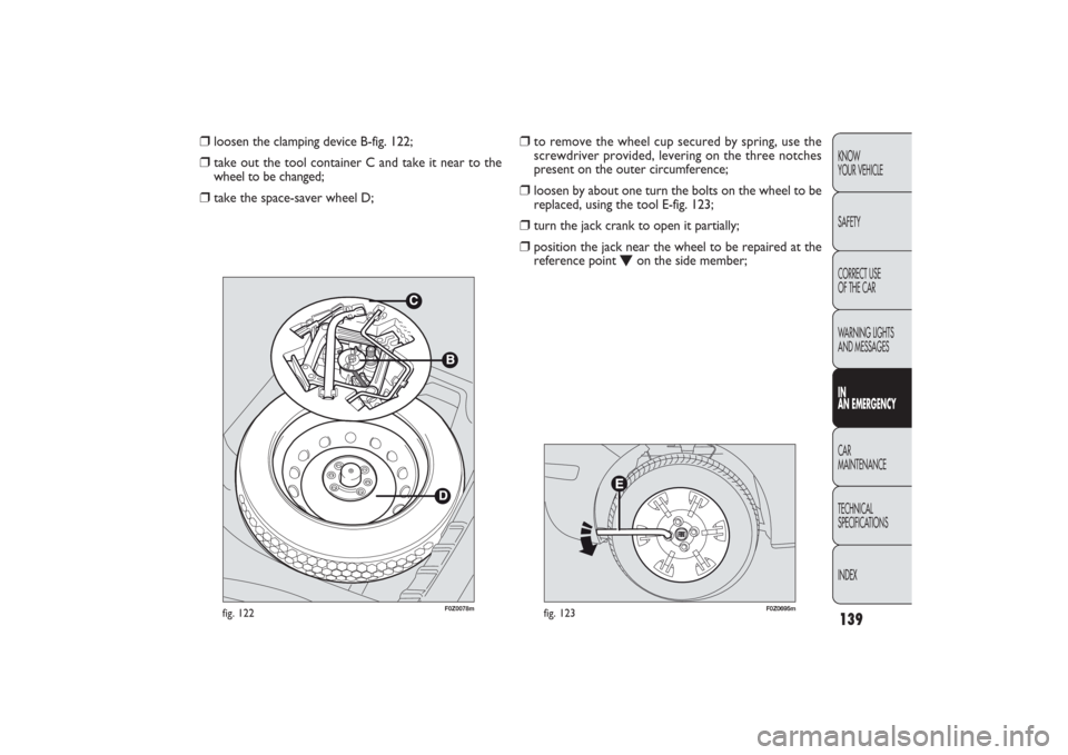
to remove the wheel cup secured by spring, use the
screwdriver provided, levering on the three notches
present on the outer circumference;
❒
loosen by about one turn the bolts on the wheel to be
replaced, using the tool E-fig. 123;
❒
turn the jack crank to open it partially;
❒
position the jack near the wheel to be repaired at the
reference point
O
on the side member;
❒
loosen the clamping device B-fig. 122;
❒
take out the tool container C and take it near to the
wheel to be changed;
❒
take the space-saver wheel D;
135-168 PANDA EN 7-10-2009 14:06 Pagina 139
Page 141 of 226
140KNOW
YOUR VEHICLE
SAFETY
CORRECT USE
OF THE CAR
WARNING LIGHTS
AND MESSAGES
IN
AN EMERGENCYCAR
MAINTENANCE
TECHNICAL
SPECIFICATIONS
INDEX
F0Z0173m
fig. 124
F0Z0233m
fig. 125
❒
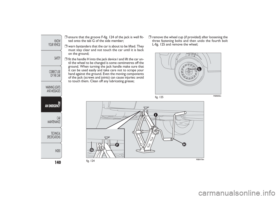
remove the wheel cup (if provided) after loosening the
three fastening bolts and then undo the fourth bolt
L-fig. 125 and remove the wheel;
❒
ensure that the groove F-fig. 124 of the jack is well fit-
ted onto the tab G of the side member;
❒
warn bystanders that the car is about to be lifted. They
must stay clear and not touch the car until it is back
on the ground;
❒
fit the handle H into the jack device
Iand lift the car un-
til the wheel to be changed is some centimetres off the
ground. When turning the jack handle make sure that
it can be used easily and take care not to scrape your
hand against the ground. Even the moving components
of the jack (screws and joints) can cause injuries: avoid
to touch them. Clean off any lubricating grease;
135-168 PANDA EN 7-10-2009 14:06 Pagina 140
Page 142 of 226
141KNOW
YOUR VEHICLE
SAFETY
CORRECT USE
OF THE CAR
WARNING LIGHTS
AND MESSAGESIN
AN EMERGENCYCAR
MAINTENANCE
TECHNICAL
SPECIFICATIONS
INDEX
F0Z0204m
fig. 126
F0Z0206m
fig. 127
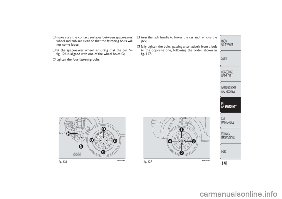
❒
turn the jack handle to lower the car and remove the
jack;
❒
fully tighten the bolts, passing alternatively from a bolt
to the opposite one, following the order shown in
fig. 127.
❒
make sure the contact surfaces between space-saver
wheel and hub are clean so that the fastening bolts will
not come loose;
❒
fit the space-saver wheel, ensuring that the pin N-
fig. 126 is aligned with one of the wheel holes O;
❒
tighten the four fastening bolts;
135-168 PANDA EN 7-10-2009 14:06 Pagina 141
Page 143 of 226
142KNOW
YOUR VEHICLE
SAFETY
CORRECT USE
OF THE CAR
WARNING LIGHTS
AND MESSAGES
IN
AN EMERGENCYCAR
MAINTENANCE
TECHNICAL
SPECIFICATIONS
INDEX
F0Z0696m
fig. 130
F0Z0603m
fig. 129
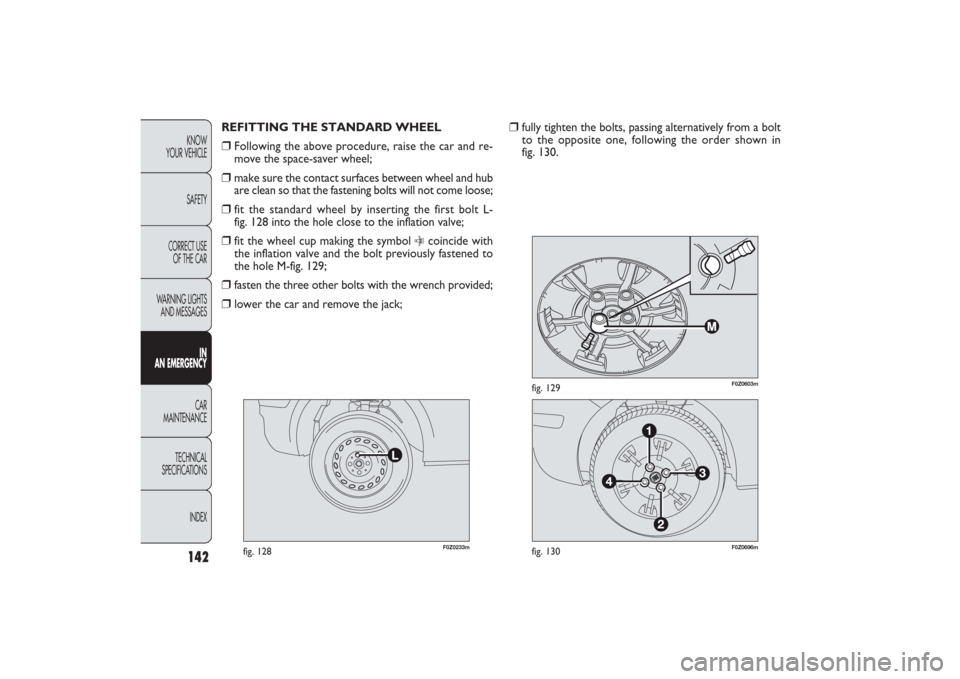
❒
fully tighten the bolts, passing alternatively from a bolt
to the opposite one, following the order shown in
fig. 130. REFITTING THE STANDARD WHEEL
❒
Following the above procedure, raise the car and re-
move the space-saver wheel;
❒
make sure the contact surfaces between wheel and hub
are clean so that the fastening bolts will not come loose;
❒
fit the standard wheel by inserting the first bolt L-
fig. 128 into the hole close to the inflation valve;
❒
fit the wheel cup making the symbol
C
coincide with
the inflation valve and the bolt previously fastened to
the hole M-fig. 129;
❒
fasten the three other bolts with the wrench provided;
❒
lower the car and remove the jack;
F0Z0233m
fig. 128
135-168 PANDA EN 7-10-2009 14:06 Pagina 142