FIAT QUBO 2010 1.G Owners Manual
QUBO 2010 1.G
FIAT
FIAT
https://www.carmanualsonline.info/img/10/4712/w960_4712-0.png
FIAT QUBO 2010 1.G Owners Manual
Trending: height adjustment, dashboard, remote start, oil type, trip computer, fuel cap, immobilizer
Page 151 of 230
THIRD BRAKE LIGHTS
Tailgate versions
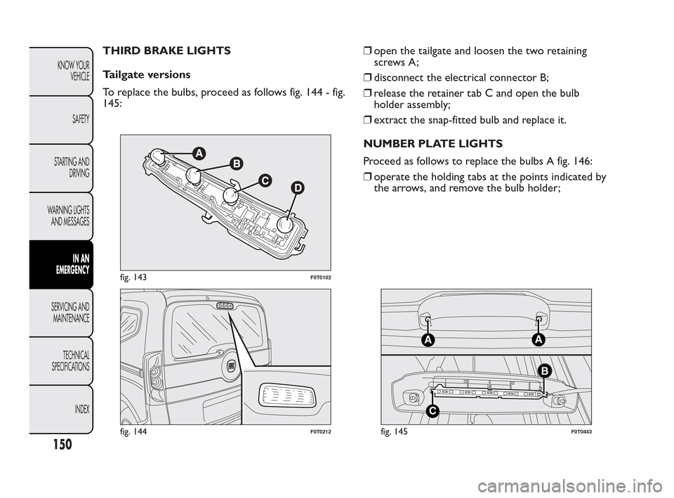
To replace the bulbs, proceed as follows fig. 144 - fig.
145:ā¯’open the tailgate and loosen the two retaining
screws A;
ā¯’disconnect the electrical connector B;
ā¯’release the retainer tab C and open the bulb
holder assembly;
ā¯’extract the snap-fitted bulb and replace it.
NUMBER PLATE LIGHTS
Proceed as follows to replace the bulbs A fig. 146:
ā¯’operate the holding tabs at the points indicated by
the arrows, and remove the bulb holder;
fig. 143F0T0102
fig. 144F0T0212
A
C
A
B
fig. 145F0T0443
150
KNOW YOUR
VEHICLE
SAFETY
STARTING AND
DRIVING
WARNING LIGHTS
AND MESSAGES
IN AN
EMERGENCY
SERVICING AND
MAINTENANCE
TECHNICAL
SPECIFICA
TIONS
INDEX
Page 152 of 230
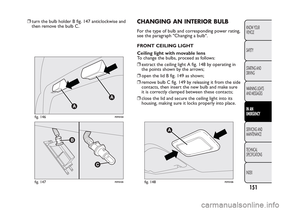
ā¯’turn the bulb holder B fig. 147 anticlockwise and
then remove the bulb C.CHANGING AN INTERIOR BULB
For the type of bulb and corresponding power rating,
see the paragraph "Changing a bulb".
FRONT CEILING LIGHT
Ceiling light with movable lens
To change the bulbs, proceed as follows:
ā¯’extract the ceiling light A fig. 148 by operating in
the points shown by the arrows;
ā¯’open the lid B fig. 149 as shown;
ā¯’remove bulb C fig. 149 by releasing it from the side
contacts, then insert the new bulb and make sure
it is correctly clamped between these contacts;
ā¯’close the lid and secure the ceiling light into its
housing, making sure it locks properly into place.
fig. 146F0T0104
fig. 147F0T0105fig. 148F0T0106
151
KNOW YOUR
VEHICLE
SAFETY
STARTING AND
DRIVING
WARNING LIGHTS
AND MESSAGES
IN AN
EMERGENCY
SERVICING AND
MAINTENANCE
TECHNICAL
SPECIFICA
TIONS
INDEX
Page 153 of 230
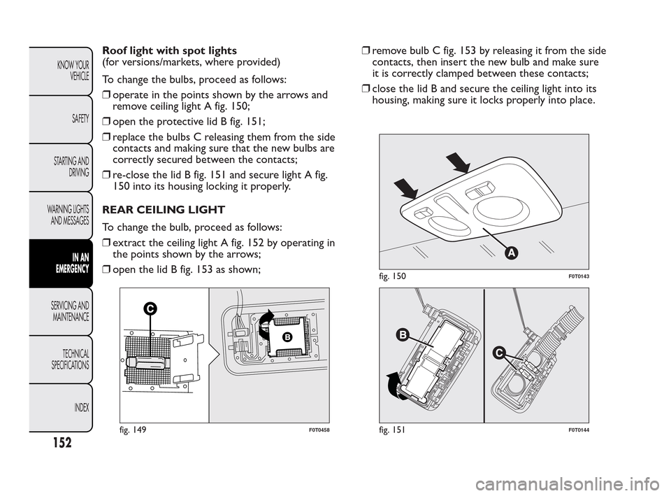
Roof light with spot lights
(for versions/markets, where provided)
To change the bulbs, proceed as follows:
ā¯’operate in the points shown by the arrows and
remove ceiling light A fig. 150;
ā¯’open the protective lid B fig. 151;
ā¯’replace the bulbs C releasing them from the side
contacts and making sure that the new bulbs are
correctly secured between the contacts;
ā¯’re-close the lid B fig. 151 and secure light A fig.
150 into its housing locking it properly.
REAR CEILING LIGHT
To change the bulb, proceed as follows:
ā¯’extract the ceiling light A fig. 152 by operating in
the points shown by the arrows;
ā¯’open the lid B fig. 153 as shown;ā¯’remove bulb C fig. 153 by releasing it from the side
contacts, then insert the new bulb and make sure
it is correctly clamped between these contacts;
ā¯’close the lid B and secure the ceiling light into its
housing, making sure it locks properly into place.
fig. 149F0T0458
fig. 150F0T0143
fig. 151F0T0144
152
KNOW YOUR
VEHICLE
SAFETY
STARTING AND
DRIVING
WARNING LIGHTS
AND MESSAGES
IN AN
EMERGENCY
SERVICING AND
MAINTENANCE
TECHNICAL
SPECIFICA
TIONS
INDEX
Page 154 of 230
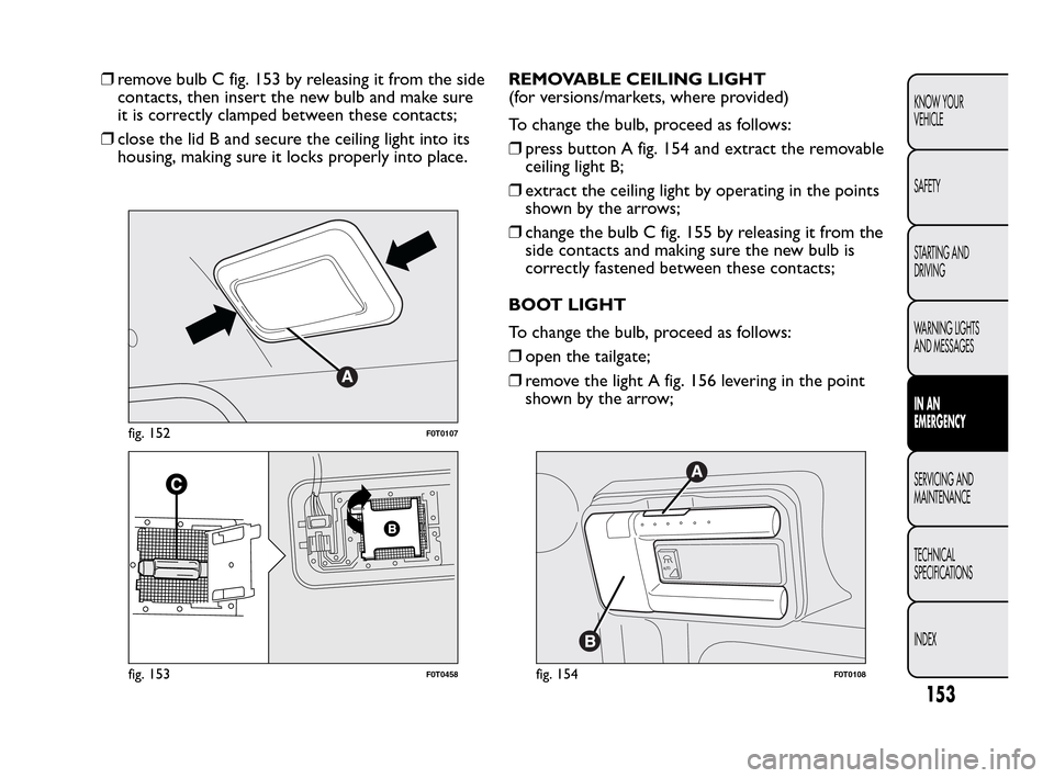
ā¯’remove bulb C fig. 153 by releasing it from the side
contacts, then insert the new bulb and make sure
it is correctly clamped between these contacts;
ā¯’close the lid B and secure the ceiling light into its
housing, making sure it locks properly into place.REMOVABLE CEILING LIGHT
(for versions/markets, where provided)
To change the bulb, proceed as follows:
ā¯’press button A fig. 154 and extract the removable
ceiling light B;
ā¯’extract the ceiling light by operating in the points
shown by the arrows;
ā¯’change the bulb C fig. 155 by releasing it from the
side contacts and making sure the new bulb is
correctly fastened between these contacts;
BOOT LIGHT
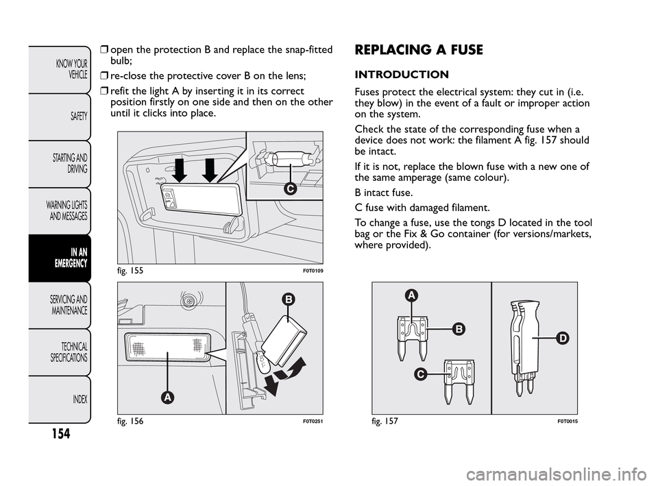
To change the bulb, proceed as follows:
ā¯’open the tailgate;
ā¯’remove the light A fig. 156 levering in the point
shown by the arrow;
fig. 152F0T0107
fig. 153F0T0458
A
UT
O
fig. 154F0T0108
153
KNOW YOUR
VEHICLE
SAFETY
STARTING AND
DRIVING
WARNING LIGHTS
AND MESSAGES
IN AN
EMERGENCY
SERVICING AND
MAINTENANCE
TECHNICAL
SPECIFICA
TIONS
INDEX
Page 155 of 230
ā¯’open the protection B and replace the snap-fitted
bulb;
ā¯’re-close the protective cover B on the lens;
ā¯’refit the light A by inserting it in its correct
position firstly on one side and then on the other
until it clicks into place.REPLACING A FUSE
INTRODUCTION
Fuses protect the electrical system: they cut in (i.e.
they blow) in the event of a fault or improper action
on the system.
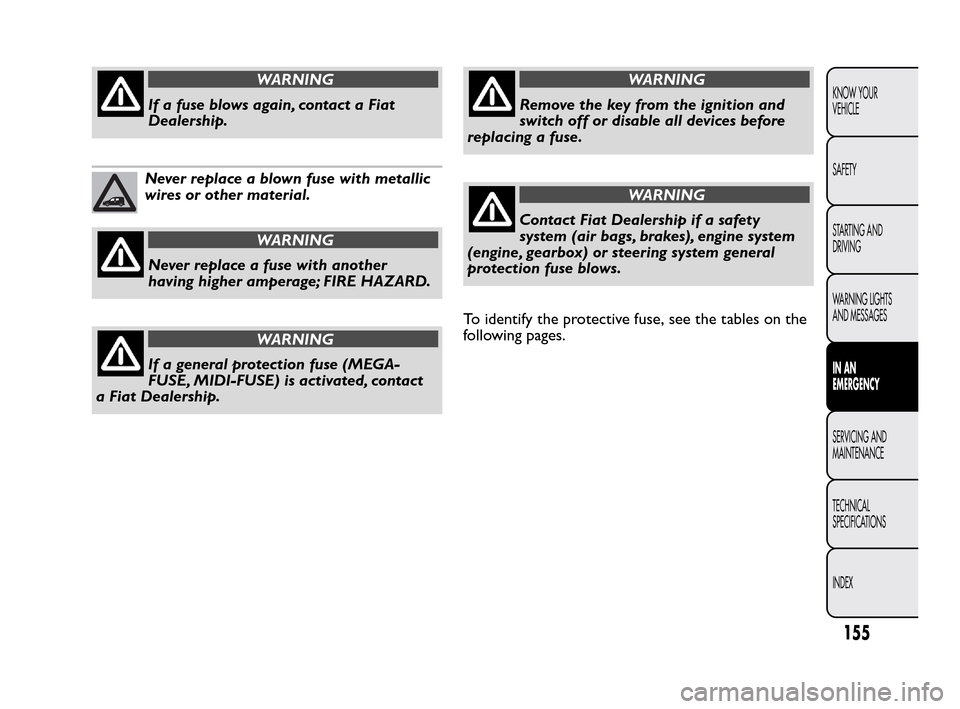
Check the state of the corresponding fuse when a
device does not work: the filament A fig. 157 should
be intact.
If it is not, replace the blown fuse with a new one of
the same amperage (same colour).
B intact fuse.
C fuse with damaged filament.
To change a fuse, use the tongs D located in the tool
bag or the Fix & Go container (for versions/markets,
where provided).
A
UT
O
fig. 155F0T0109
fig. 156F0T0251fig. 157F0T0015
154
KNOW YOUR
VEHICLE
SAFETY
STARTING AND
DRIVING
WARNING LIGHTS
AND MESSAGES
IN AN
EMERGENCY
SERVICING AND
MAINTENANCE
TECHNICAL
SPECIFICA
TIONS
INDEX
Page 156 of 230
WARNING
If a fuse blows again, contact a Fiat
Dealer
ship.
Never replace a blown fuse with metallic
wires or other material.
WARNING
Never replace a fuse with another
h
aving higher amperage; FIRE HAZARD.
WARNING
If a general protection fuse (MEGA-
FUSE
, MIDI-FUSE) is activated, contact
a Fiat Dealership.
WARNING
Remove the key from the ignition and
s
witch off or disable all devices before
replacing a fuse.
WARNING
Contact Fiat Dealership if a safety
sys
tem (air bags, brakes), engine system
(engine, gearbox) or steering system general
protection fuse blows.
To identify the protective fuse, see the tables on the
following pages.
155
KNOW YOUR
VEHICLE
SAFETY
STARTING AND
DRIVING
WARNING LIGHTS
AND MESSAGES
IN AN
EMERGENCY
SERVICING AND
MAINTENANCE
TECHNICAL
SPECIFICA
TIONS
INDEX
Page 157 of 230
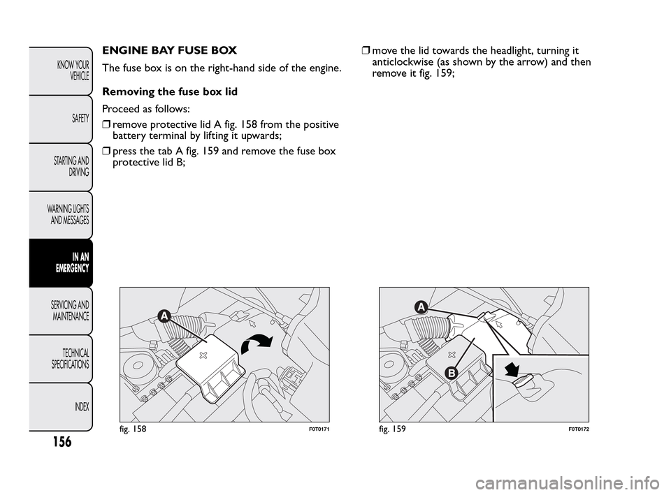
ENGINE BAY FUSE BOX
The fuse box is on the right-hand side of the engine.
Removing the fuse box lid
Proceed as follows:
ā¯’remove protective lid A fig. 158 from the positive
battery terminal by lifting it upwards;
ā¯’press the tab A fig. 159 and remove the fuse box
protective lid B;ā¯’move the lid towards the headlight, turning it
anticlockwise (as shown by the arrow) and then
remove it fig. 159;
fig. 158F0T0171fig. 159F0T0172
156
KNOW YOUR
VEHICLE
SAFETY
STARTING AND
DRIVING
WARNING LIGHTS
AND MESSAGES
IN AN
EMERGENCY
SERVICING AND
MAINTENANCE
TECHNICAL
SPECIFICA
TIONS
INDEX
Page 158 of 230
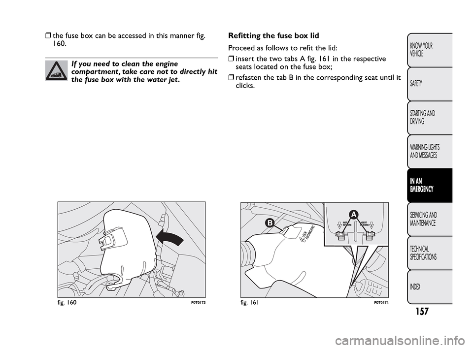
ā¯’the fuse box can be accessed in this manner fig.
160.
If you need to clean the engine
compartment , take care not to directly hit
the fuse box with the water jet .Refitting the fuse box lid
Proceed as follows to refit the lid:
ā¯’insert the two tabs A fig. 161 in the respective
seats located on the fuse box;
ā¯’refasten the tab B in the corresponding seat until it
clicks.
fig. 160F0T0173fig. 161F0T0174
157
KNOW YOUR
VEHICLE
SAFETY
STARTING AND
DRIVING
WARNING LIGHTS
AND MESSAGES
IN AN
EMERGENCY
SERVICING AND
MAINTENANCE
TECHNICAL
SPECIFICA
TIONS
INDEX
Page 159 of 230
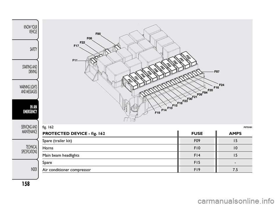
PROTECTED DEVICE - fig. 162 FUSE AMPS
Spare (trailer kit) F09 15
HornsF10 10
Main beam headlights F14 15
SpareF15 -
Air conditioner compressor F19 7.5
fig. 162F0T0181
158
KNOW YOUR
VEHICLE
SAFETY
STARTING AND
DRIVING
WARNING LIGHTS
AND MESSAGES
IN AN
EMERGENCY
SERVICING AND
MAINTENANCE
TECHNICAL
SPECIFICA
TIONS
INDEX
Page 160 of 230
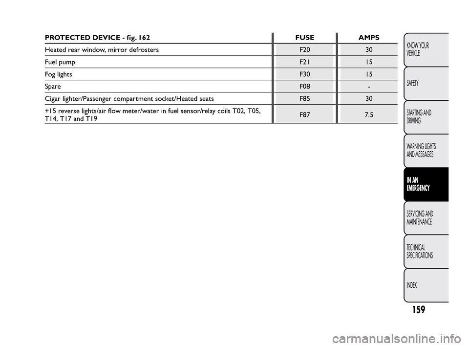
PROTECTED DEVICE - fig. 162 FUSE AMPS
Heated rear window, mirror defrosters F20 30
Fuel pump F21 15
Fog lights F30 15
SpareF08 -
Cigar lighter/Passenger compartment socket/Heated seats F85 30
+15 reverse lights/air flow meter/water in fuel sensor/relay coils T02, T05,
T14, T17 and T19F87 7.5
159
KNOW YOUR
VEHICLE
SAFETY
STARTING AND
DRIVING
WARNING LIGHTS
AND MESSAGES
IN AN
EMERGENCY
SERVICING AND
MAINTENANCE
TECHNICAL
SPECIFICA
TIONS
INDEX
Trending: SBR system, oil pressure, adding oil, maintenance reset, technical data, lock, buttons
