FIAT QUBO 2010 1.G Repair Manual
Manufacturer: FIAT, Model Year: 2010, Model line: QUBO, Model: FIAT QUBO 2010 1.GPages: 230, PDF Size: 4.38 MB
Page 61 of 230
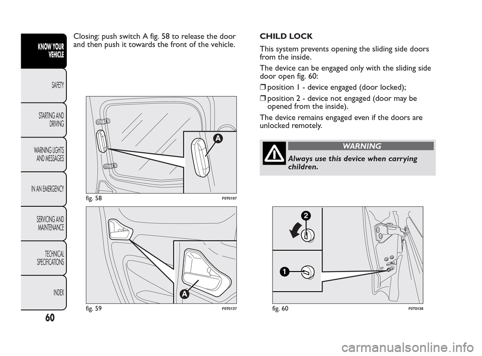
Closing: push switch A fig. 58 to release the door
and then push it towards the front of the vehicle.CHILD LOCK
This system prevents opening the sliding side doors
from the inside.
The device can be engaged only with the sliding side
door open fig. 60:
❒position1-device engaged (door locked);
❒position2-device not engaged (door may be
opened from the inside).
The device remains engaged even if the doors are
unlocked remotely.
WARNING
Always use this device when carrying
children.
fig. 58F0T0197
fig. 59F0T0137
1
2
fig. 60F0T0138
60
KNOW YOUR
VEHICLE
SAFETY
ST
ARTING AND
DRIVING
WARNING LIGHTS
AND MESSAGES
IN AN EMERGENCY
SERVICING AND
MAINTENANCE
TECHNICAL
SPECIFICATIONS
INDEX
Page 62 of 230
WINDOWS
FRONT ELECTRIC WINDOWS
(for versions/markets, where provided)
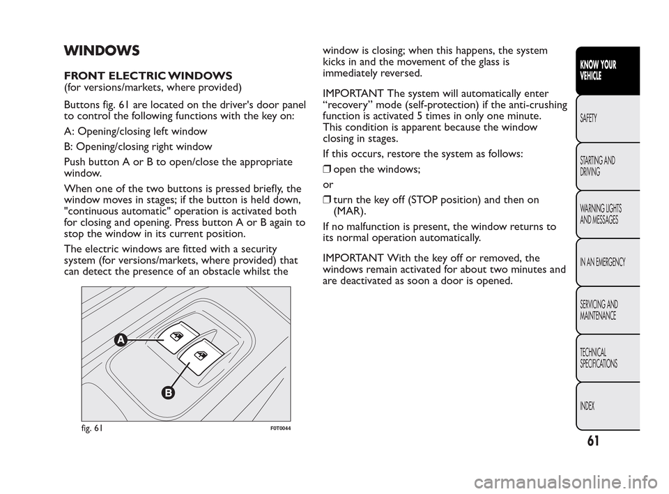
Buttons fig. 61 are located on the driver's door panel
to control the following functions with the key on:
A: Opening/closing left window
B: Opening/closing right window
Push button A or B to open/close the appropriate
window.
When one of the two buttons is pressed briefly, the
window moves in stages; if the button is held down,
"continuous automatic" operation is activated both
for closing and opening. Press button A or B again to
stop the window in its current position.
The electric windows are fitted with a security
system (for versions/markets, where provided) that
can detect the presence of an obstacle whilst thewindow is closing; when this happens, the system
kicks in and the movement of the glass is
immediately reversed.
IMPORTANT The system will automatically enter
“recovery” mode (self-protection) if the anti-crushing
function is activated 5 times in only one minute.
This condition is apparent because the window
closing in stages.
If this occurs, restore the system as follows:
❒open the windows;
or
❒turn the key off (STOP position) and then on
(MAR).
If no malfunction is present, the window returns to
its normal operation automatically.
IMPORTANT With the key off or removed, the
windows remain activated for about two minutes and
are deactivated as soon a door is opened.
fig. 61F0T0044
61
KNOW YOUR
VEHICLE
SAFETY
ST
ARTING AND
DRIVING
WARNING LIGHTS
AND MESSAGES
IN AN EMERGENCY
SERVICING AND
MAINTENANCE
TECHNICAL
SPECIFICATIONS
INDEX
Page 63 of 230
WARNING
Improper use of the electric windows
can
be dangerous. Before and during
operation, always check that no-one is exposed
to the risk of being injured directly by the
moving window or by objects getting caught and
dragged. When leaving the car, always remove
the ignition key to avoid the risk of injury
due to accidental operation of the electric
windows.
MANUAL FRONT WINDOWS
On some versions, the front windows are opened
and closed manually.
Wind the handle to open/close.
BOOT
OPENING THE TAILGATE FROM THE
OUTSIDE
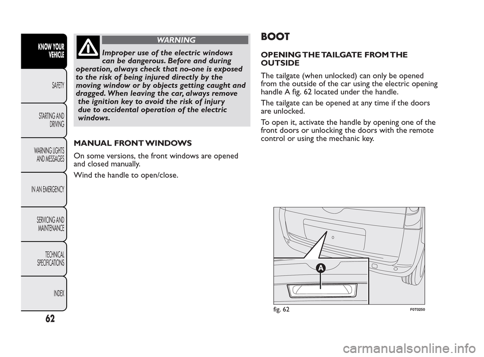
The tailgate (when unlocked) can only be opened
from the outside of the car using the electric opening
handle A fig. 62 located under the handle.
The tailgate can be opened at any time if the doors
are unlocked.
To open it, activate the handle by opening one of the
front doors or unlocking the doors with the remote
control or using the mechanic key.
fig. 62F0T0250
62
KNOW YOUR
VEHICLE
SAFETY
ST
ARTING AND
DRIVING
WARNING LIGHTS
AND MESSAGES
IN AN EMERGENCY
SERVICING AND
MAINTENANCE
TECHNICAL
SPECIFICATIONS
INDEX
Page 64 of 230
EMERGENCY OPENING FROM THE INSIDE
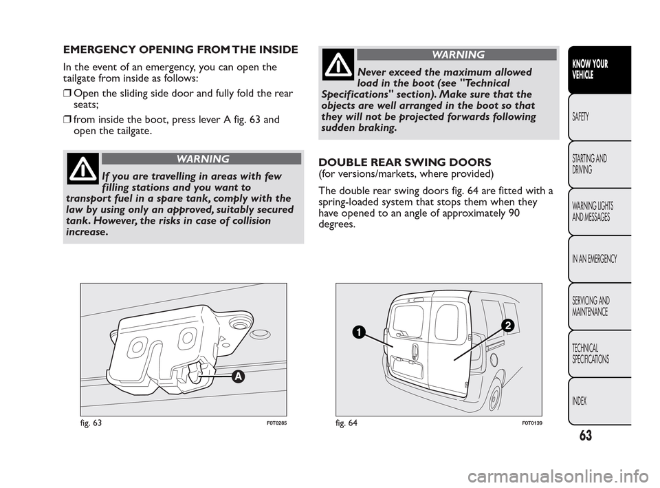
In the event of an emergency, you can open the
tailgate from inside as follows:
❒Open the sliding side door and fully fold the rear
seats;
❒from inside the boot, press lever A fig. 63 and
open the tailgate.
WARNING
If you are travelling in areas with few
f
illing stations and you want to
transport fuel in a spare tank, comply with the
law by using only an approved, suitably secured
tank.However, the risks in case of collision
increase.
WARNING
Never exceed the maximum allowed
load
in the boot (see "Technical
Specifications" section). Make sure that the
objects are well arranged in the boot so that
they will not be projected forwards following
sudden braking.
DOUBLE REAR SWING DOORS
(for versions/markets, where provided)
The double rear swing doors fig. 64 are fitted with a
spring-loaded system that stops them when they
have opened to an angle of approximately 90
degrees.
fig. 63F0T0285fig. 64F0T0139
63
KNOW YOUR
VEHICLE
SAFETY
ST
ARTING AND
DRIVING
WARNING LIGHTS
AND MESSAGES
IN AN EMERGENCY
SERVICING AND
MAINTENANCE
TECHNICAL
SPECIFICATIONS
INDEX
Page 65 of 230
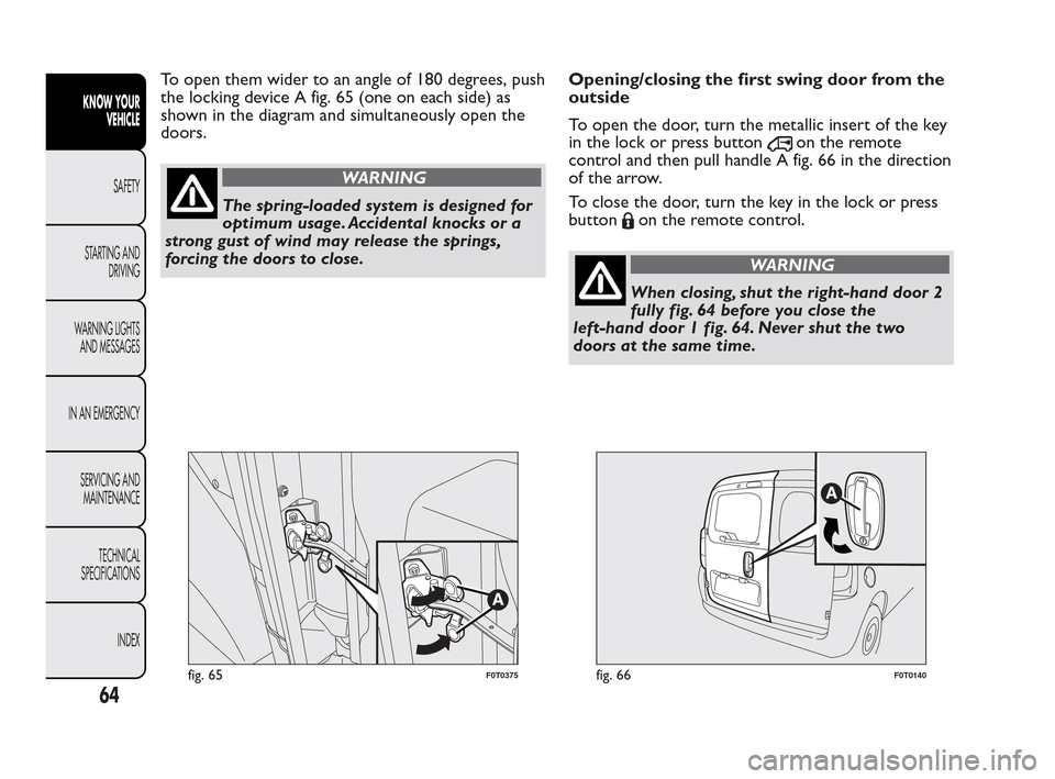
To open them wider to an angle of 180 degrees, push
the locking device A fig. 65 (one on each side) as
shown in the diagram and simultaneously open the
doors.
WARNING
The spring-loaded system is designed for
o
ptimum usage. Accidental knocks or a
strong gust of wind may release the springs,
forcing the doors to close.Opening/closing the first swing door from the
outside
To open the door, turn the metallic insert of the key
in the lock or press button
on the remote
control and then pull handle A fig. 66 in the direction
of the arrow.
To close the door, turn the key in the lock or press
button
on the remote control.
WARNING
When closing, shut the right-hand door 2
fully
fig. 64 before you close the
left-hand door 1 fig. 64. Never shut the two
doors at the same time.
fig. 65F0T0375fig. 66F0T0140
64
KNOW YOUR
VEHICLE
SAFETY
ST
ARTING AND
DRIVING
WARNING LIGHTS
AND MESSAGES
IN AN EMERGENCY
SERVICING AND
MAINTENANCE
TECHNICAL
SPECIFICATIONS
INDEX
Page 66 of 230
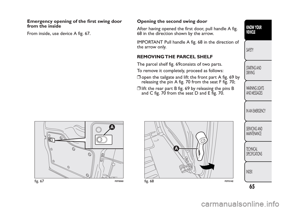
Emergency opening of the first swing door
from the inside
From inside, use device A fig. 67.Opening the second swing door
After having opened the first door, pull handle A fig.
68 in the direction shown by the arrow.
IMPORTANT Pull handle A fig. 68 in the direction of
the arrow only.
REMOVING THE PARCEL SHELF
The parcel shelf fig. 69consists of two parts.
To remove it completely, proceed as follows:
❒open the tailgate and lift the front part A fig. 69 by
releasing the pin A fig. 70 from the seat F fig. 70;
❒lift the rear part B fig. 69 by releasing the pins B
and C fig. 70 from the seat D and E fig. 70.
fig. 67F0T0060fig. 68F0T0142
65
KNOW YOUR
VEHICLE
SAFETY
ST
ARTING AND
DRIVING
WARNING LIGHTS
AND MESSAGES
IN AN EMERGENCY
SERVICING AND
MAINTENANCE
TECHNICAL
SPECIFICATIONS
INDEX
Page 67 of 230
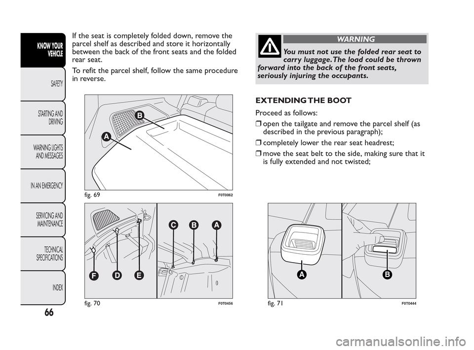
If the seat is completely folded down, remove the
parcel shelf as described and store it horizontally
between the back of the front seats and the folded
rear seat.
To refit the parcel shelf, follow the same procedure
in reverse.WARNING
You must not use the folded rear seat to
carr
y luggage.The load could be thrown
forward into the back of the front seats,
seriously injuring the occupants.
EXTENDING THE BOOT
Proceed as follows:
❒open the tailgate and remove the parcel shelf (as
described in the previous paragraph);
❒completely lower the rear seat headrest;
❒move the seat belt to the side, making sure that it
is fully extended and not twisted;
fig. 69F0T0062
fig. 70F0T0456
BA
fig. 71F0T0444
66
KNOW YOUR
VEHICLE
SAFETY
ST
ARTING AND
DRIVING
WARNING LIGHTS
AND MESSAGES
IN AN EMERGENCY
SERVICING AND
MAINTENANCE
TECHNICAL
SPECIFICATIONS
INDEX
Page 68 of 230
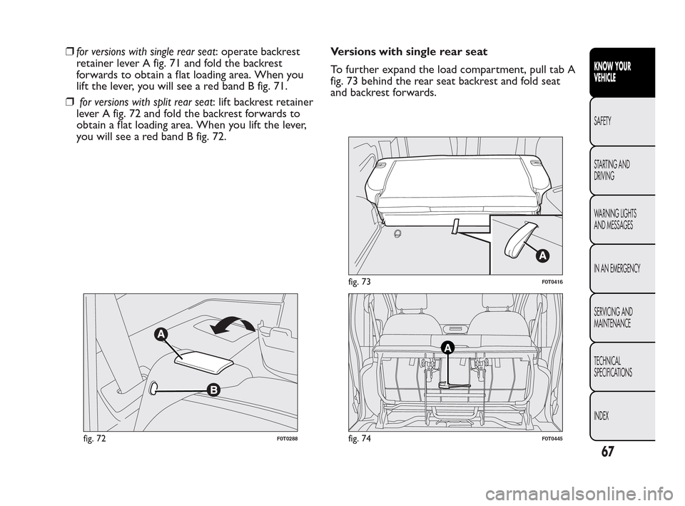
❒for versions with single rear seat: operate backrest
retainer lever A fig. 71 and fold the backrest
forwards to obtain a flat loading area. When you
lift the lever, you will see a red band B fig. 71.
❒for versions with split rear seat: lift backrest retainer
lever A fig. 72 and fold the backrest forwards to
obtain a flat loading area. When you lift the lever,
you will see a red band B fig. 72.Versions with single rear seat
To further expand the load compartment, pull tab A
fig. 73 behind the rear seat backrest and fold seat
and backrest forwards.
fig. 72F0T0288
fig. 73F0T0416
A
fig. 74F0T0445
67
KNOW YOUR
VEHICLE
SAFETY
ST
ARTING AND
DRIVING
WARNING LIGHTS
AND MESSAGES
IN AN EMERGENCY
SERVICING AND
MAINTENANCE
TECHNICAL
SPECIFICATIONS
INDEX
Page 69 of 230
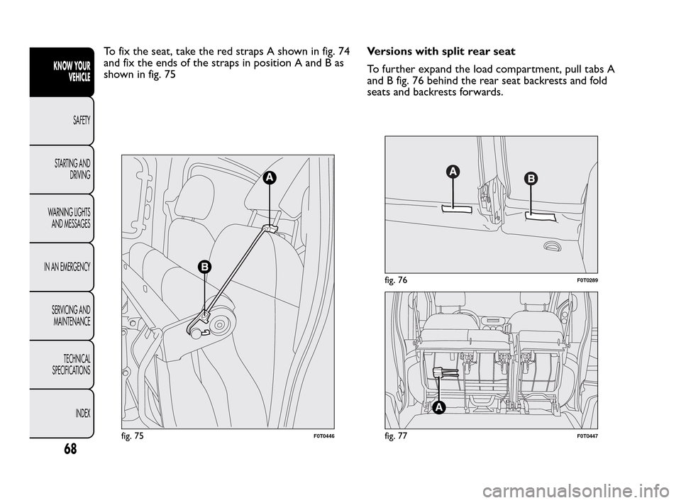
To fix the seat, take the red straps A shown in fig. 74
and fix the ends of the straps in position A and B as
shown in fig. 75Versions with split rear seat
To further expand the load compartment, pull tabs A
and B fig. 76 behind the rear seat backrests and fold
seats and backrests forwards.
fig. 75F0T0446
fig. 76F0T0289
A
fig. 77F0T0447
68
KNOW YOUR
VEHICLE
SAFETY
ST
ARTING AND
DRIVING
WARNING LIGHTS
AND MESSAGES
IN AN EMERGENCY
SERVICING AND
MAINTENANCE
TECHNICAL
SPECIFICATIONS
INDEX
Page 70 of 230
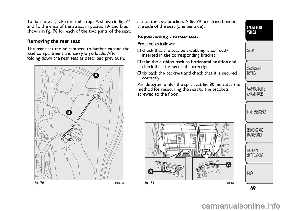
To fix the seat, take the red straps A shown in fig. 77
and fix the ends of the straps in position A and B as
shown in fig. 78 for each of the two parts of the seat.
Removing the rear seat
The rear seat can be removed to further expand the
load compartment and carry large loads. After
folding down the rear seat as described previously,act on the two brackets A fig. 79 positioned under
the side of the seat (one per side).
Repositioning the rear seat
Proceed as follows:
❒check that the seat belt webbing is correctly
inserted in the corresponding bracket:
❒take the cushion back to horizontal position and
check that it is secured correctly;
❒tip back the backrest and check that it is secured
correctly.
An ideogram under the split seat fig. 80 indicates the
method for resecuring the seat to the brackets
screwed to the floor.
fig. 78F0T0448fig. 79F0T0455
69
KNOW YOUR
VEHICLE
SAFETY
ST
ARTING AND
DRIVING
WARNING LIGHTS
AND MESSAGES
IN AN EMERGENCY
SERVICING AND
MAINTENANCE
TECHNICAL
SPECIFICATIONS
INDEX