technical specifications FIAT SCUDO 2010 Owner handbook (in English)
[x] Cancel search | Manufacturer: FIAT, Model Year: 2010, Model line: SCUDO, Model: FIAT SCUDO 2010Pages: 210, PDF Size: 3.32 MB
Page 45 of 210

44
SAFETY
DEVICES
CORRECT USE
OF THE
VEHICLE
WARNING
LIGHTS AND
MESSAGES
IN AN
EMERGENCY
VEHICLE
MAINTENANCE
TECHNICAL
SPECIFICATIONS
INDEX
DASHBOARD
AND
CONTROLS
Switching the climate control
system off (A/C) A
Press button Ato turn the system off.
When turned off the system conditions
are the following:
❒set temperature displays off;
❒air recirculation is on;
❒conditioner compressor off;
❒fan off.
Heated rear window can be turned on or
off also when the system is off.
IMPORTANT The system will store the
temperatures set before turning off and
will resume them when pressing any but-
ton (except heated rear window); if the
function corresponding to the button
pressed is off it will be turned on; if on it
will be kept active.
Press AUTOto turn the system in au-
tomatic mode.ADDITIONAL HEATER
(where provided)
This device shall be used to speed up pas-
senger compartment warming when it is
very cold.
The additional heater turns off automati-
cally after reaching the required comfort
conditions.
Automatic two-zone climate
control system
The additional heater will switch on au-
tomatically after turning the ignition key
to MAR.Manual Heater and Climate
control system
The additional heater will switch on au-
tomatically by turning knob M or Ito the
last red sector and turning the fan on
(knob D) to the first speed at least.
IMPORTANT Heater works only with
low outside temperature and engine
coolant temperature.
IMPORTANT Heater will not turn on if
the battery voltage is not sufficient.
Page 46 of 210
45
SAFETY
DEVICES
CORRECT USE
OF THE
VEHICLE
WARNING
LIGHTS AND
MESSAGES
IN AN
EMERGENCY
VEHICLE
MAINTENANCE
TECHNICAL
SPECIFICATIONS
INDEX
DASHBOARD
AND CONTROLS
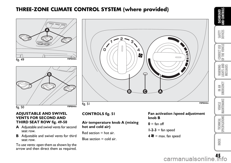
CONTROLS fig. 51
Air temperature knob A (mixing
hot and cold air)
Red section = hot air.
Blue section = cold air.Fan activation /speed adjustment
knob B
0= fan off
1-2-3= fan speed
4 p= max. fan speed
fig. 51F0P0043m
ADJUSTABLE AND SWIVEL
VENTS FOR SECOND AND
THIRD SEAT ROW fig. 49-50
AAdjustable and swivel vents for second
seat row.
BAdjustable and swivel vents for third
seat row.
To use vents: open them as shown by the
arrow and then direct them as required.
THREE-ZONE CLIMATE CONTROL SYSTEM (where provided)
fig. 49F0P0042m
fig. 50F0P0044m
Page 47 of 210
46
SAFETY
DEVICES
CORRECT USE
OF THE
VEHICLE
WARNING
LIGHTS AND
MESSAGES
IN AN
EMERGENCY
VEHICLE
MAINTENANCE
TECHNICAL
SPECIFICATIONS
INDEX
DASHBOARD
AND
CONTROLS
WARMING THE PASSENGER
COMPARTMENT
Proceed as follows:
❒knob Aturned to red section;
❒slider Bturned to the required speed.
FAST HEATING
For fast heating of the passenger com-
partment, proceed as follows:
❒knob Aturned to red section;
❒turn air recirculation on;
❒knob Bturned to 4p(max. fan speed).
Then use the controls to keep the re-
quired comfort conditions and to turn air
recirculation off.
IMPORTANT With cold engine, you have
to wait for a few minutes to let the sys-
tem fluid reach the operating temperature.
fig. 52F0P0045m
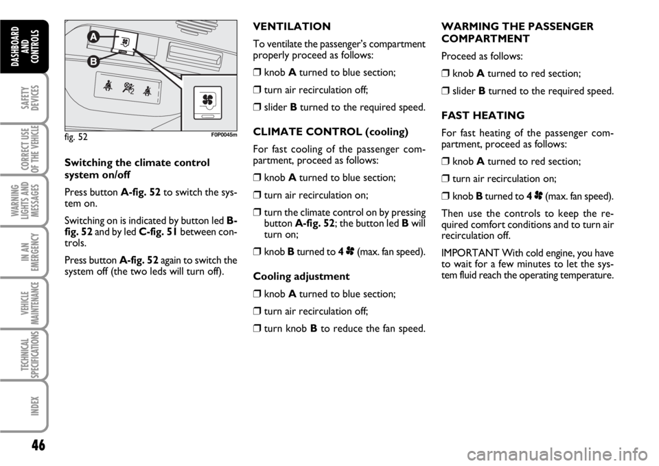
Switching the climate control
system on/off
Press button A-fig. 52to switch the sys-
tem on.
Switching on is indicated by button led B-
fig. 52and by led C-fig. 51between con-
trols.
Press button A-fig. 52again to switch the
system off (the two leds will turn off).VENTILATION
To ventilate the passenger’s compartment
properly proceed as follows:
❒knob Aturned to blue section;
❒turn air recirculation off;
❒slider Bturned to the required speed.
CLIMATE CONTROL (cooling)
For fast cooling of the passenger com-
partment, proceed as follows:
❒knob Aturned to blue section;
❒turn air recirculation on;
❒turn the climate control on by pressing
button A-fig. 52; the button led Bwill
turn on;
❒knob Bturned to 4p(max. fan speed).
Cooling adjustment
❒knob Aturned to blue section;
❒turn air recirculation off;
❒turn knob Bto reduce the fan speed.
Page 48 of 210
47
SAFETY
DEVICES
CORRECT USE
OF THE
VEHICLE
WARNING
LIGHTS AND
MESSAGES
IN AN
EMERGENCY
VEHICLE
MAINTENANCE
TECHNICAL
SPECIFICATIONS
INDEX
DASHBOARD
AND CONTROLS
EXTERNAL LIGHTS
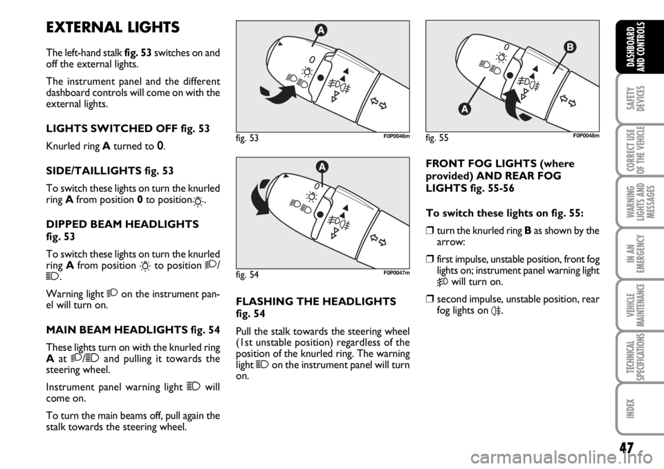
The left-hand stalk fig. 53switches on and
off the external lights.
The instrument panel and the different
dashboard controls will come on with the
external lights.
LIGHTS SWITCHED OFF fig. 53
Knurled ring Aturned to 0.
SIDE/TAILLIGHTS fig. 53
To switch these lights on turn the knurled
ring Afrom position 0 to position
6.
DIPPED BEAM HEADLIGHTS
fig. 53
To switch these lights on turn the knurled
ring Afrom position
6to position 2/1.
Warning light 2on the instrument pan-
el will turn on.
MAIN BEAM HEADLIGHTS fig. 54
These lights turn on with the knurled ring
Aat 2/1and pulling it towards the
steering wheel.
Instrument panel warning light 1will
come on.
To turn the main beams off, pull again the
stalk towards the steering wheel.FLASHING THE HEADLIGHTS
fig. 54
Pull the stalk towards the steering wheel
(1st unstable position) regardless of the
position of the knurled ring. The warning
light
1on the instrument panel will turn
on.
fig. 53F0P0046m
fig. 54F0P0047m
fig. 55F0P0048m
FRONT FOG LIGHTS (where
provided) AND REAR FOG
LIGHTS fig. 55-56
To switch these lights on fig. 55:
❒turn the knurled ring Bas shown by the
arrow:
❒first impulse, unstable position, front fog
lights on; instrument panel warning light
5will turn on.
❒second impulse, unstable position, rear
fog lights on
4.
Page 49 of 210
48
SAFETY
DEVICES
CORRECT USE
OF THE
VEHICLE
WARNING
LIGHTS AND
MESSAGES
IN AN
EMERGENCY
VEHICLE
MAINTENANCE
TECHNICAL
SPECIFICATIONS
INDEX
DASHBOARD
AND
CONTROLS
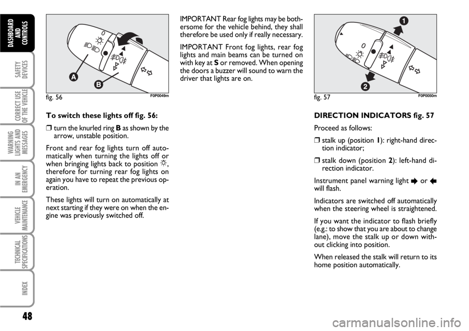
DIRECTION INDICATORS fig. 57
Proceed as follows:
❒stalk up (position 1): right-hand direc-
tion indicator;
❒stalk down (position 2): left-hand di-
rection indicator.
Instrument panel warning light
Eor Rwill flash.
Indicators are switched off automatically
when the steering wheel is straightened.
If you want the indicator to flash briefly
(e.g.: to show that you are about to change
lane), move the stalk up or down with-
out clicking into position.
When released the stalk will return to its
home position automatically.
fig. 57F0P0050mfig. 56F0P0049m
To switch these lights off fig. 56:
❒turn the knurled ring Bas shown by the
arrow, unstable position.
Front and rear fog lights turn off auto-
matically when turning the lights off or
when bringing lights back to position 6,
therefore for turning rear fog lights on
again you have to repeat the previous op-
eration.
These lights will turn on automatically at
next starting if they were on when the en-
gine was previously switched off.IMPORTANT Rear fog lights may be both-
ersome for the vehicle behind, they shall
therefore be used only if really necessary.
IMPORTANT Front fog lights, rear fog
lights and main beams can be turned on
with key at Sor removed. When opening
the doors a buzzer will sound to warn the
driver that lights are on.
Page 50 of 210
49
SAFETY
DEVICES
CORRECT USE
OF THE
VEHICLE
WARNING
LIGHTS AND
MESSAGES
IN AN
EMERGENCY
VEHICLE
MAINTENANCE
TECHNICAL
SPECIFICATIONS
INDEX
DASHBOARD
AND CONTROLS
Follow me home (where provided)
This function allows the illumination of the
space in front of the vehicle for a preset
period of time (45 seconds). To activate
it the ignition key shall be at Sor removed
and the left stalk shall be pushed towards
the dashboard within 2 minutes from
when the engine is turned off.
If the vehicle is fitted with automatic de-
vice for turning on side lights and dipped
beams, the follow me home function will
activate automatically when opening the
doors.AUTOMATIC HEADLIGHTS
SENSOR (daylight sensor)
(where provided)
It detects the changes of the external light
intensity of the vehicle according to the
light sensitivity set: the greater the sensi-
tivity is, the smaller the amount of exter-
nal light necessary to control the switch-
ing-on of the external headlights will be.
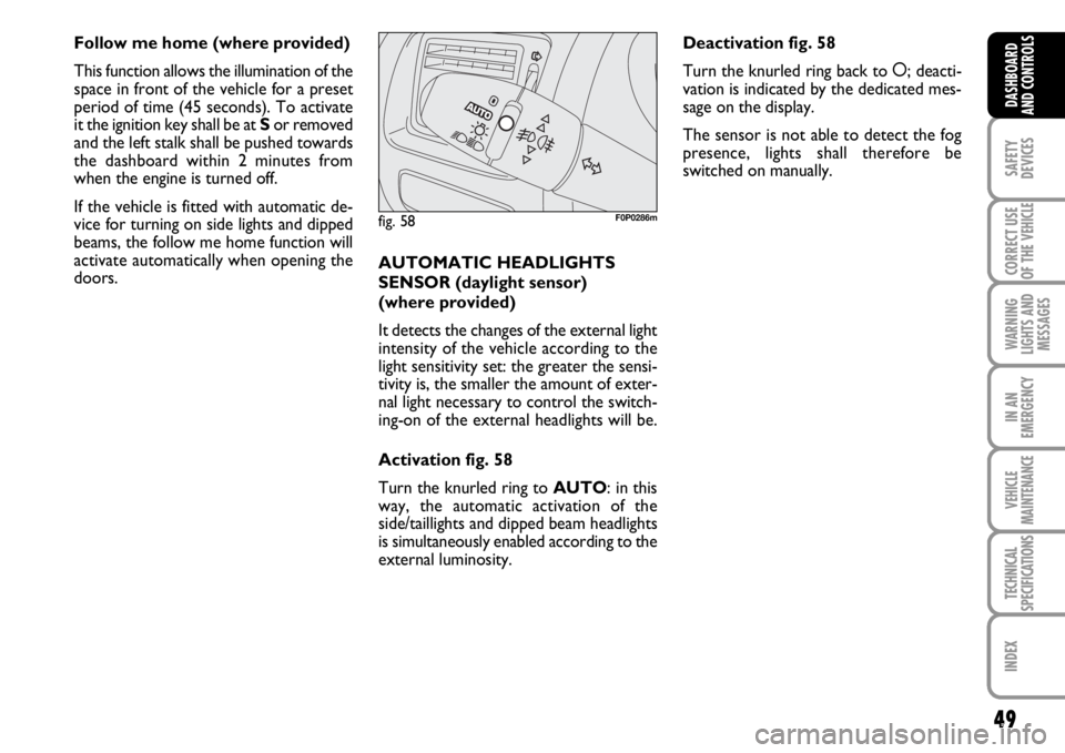
Activation fig. 58
Turn the knurled ring to AUTO: in this
way, the automatic activation of the
side/taillights and dipped beam headlights
is simultaneously enabled according to the
external luminosity.
fig. 58F0P0286m
Deactivation fig. 58
Turn the knurled ring back to å; deacti-
vation is indicated by the dedicated mes-
sage on the display.
The sensor is not able to detect the fog
presence, lights shall therefore be
switched on manually.
Page 51 of 210
50
SAFETY
DEVICES
CORRECT USE
OF THE
VEHICLE
WARNING
LIGHTS AND
MESSAGES
IN AN
EMERGENCY
VEHICLE
MAINTENANCE
TECHNICAL
SPECIFICATIONS
INDEX
DASHBOARD
AND
CONTROLS
WINDOW WASHING
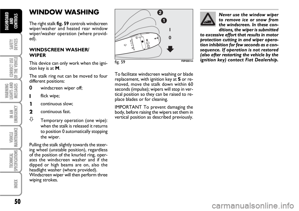
The right stalk fig. 59controls windscreen
wiper/washer and heated rear window
wiper/washer operation (where provid-
ed).
WINDSCREEN WASHER/
WIPER
This device can only work when the igni-
tion key is at M.
The stalk ring nut can be moved to four
different positions:
0windscreen wiper off;
Iflick wipe;
1continuous slow;
2continuous fast.
STemporary operation (one wipe):
when the stalk is released it returns
to position 0 automatically stopping
the wiper.
Pulling the stalk slightly towards the steer-
ing wheel (unstable position), regardless
of the position of the knurled ring, oper-
ates the windscreen washer and if the
dipped or high beams are on, also the
headlight washer (where provided).
Windscreen wiper will then perform three
wiping strokes.Never use the window wiper
to remove ice or snow from
the windscreen. In these con-
ditions, the wiper is submitted
to excessive effort that results in motor
protection cutting in and wiper opera-
tion inhibition for few seconds as a con-
sequence. If operation is not restored
(also after restarting the vehicle by the
ignition key) contact Fiat Dealership.
To facilitate windscreen washing or blade
replacement, with ignition key at Sor re-
moved, move the stalk down within 60
seconds (impulse); wipers will stop in ver-
tical position so they can be raised to re-
place blades or for cleaning.
IMPORTANT To prevent damaging the
body, before raising the wipers set them in
vertical position as described previously.
fig. 59F0P0051m
Page 52 of 210
51
SAFETY
DEVICES
CORRECT USE
OF THE
VEHICLE
WARNING
LIGHTS AND
MESSAGES
IN AN
EMERGENCY
VEHICLE
MAINTENANCE
TECHNICAL
SPECIFICATIONS
INDEX
DASHBOARD
AND CONTROLS
The rain sensor (fitted on certain versions
only), is an electronic device coupled to
the windscreen wiper with the purpose of
adjusting automatically, during the inter-
mittent operation, the frequency of the
windscreen wiper strokes as to the rain
intensity.
The rain sensor will activate automatical-
ly when moving the stalk to AUTO; its
range varies gradually from windscreen
wiper off (no wipe) when the windscreen
is dry, to wiper at first continuous speed
with heavy rain.
The activation of the rain sensor is sig-
nalled by a control acquisition “stroke”. RAIN SENSOR
(where provided)
The rain sensor is located behind the dri-
ving mirror in contact with the windscreen
and has the purpose of adjusting auto-
matically, during the intermittent opera-
tion, the frequency of the windscreen
wiper strokes as to the rain intensity.
IMPORTANT Keep clean the glass in the
sensor area.
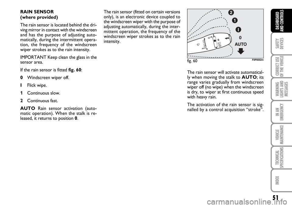
If the rain sensor is fitted fig. 60:
0Windscreen wiper off.
IFlick wipe.
1Continuous slow.
2Continuous fast.
AUTORain sensor activation (auto-
matic operation). When the stalk is re-
leased, it returns to position 0.
fig. 60F0P0052m
Page 53 of 210
52
SAFETY
DEVICES
CORRECT USE
OF THE
VEHICLE
WARNING
LIGHTS AND
MESSAGES
IN AN
EMERGENCY
VEHICLE
MAINTENANCE
TECHNICAL
SPECIFICATIONS
INDEX
DASHBOARD
AND
CONTROLS
Operating the windscreen washer with
the rain sensor activated the normal wash-
ing cycle is performed at the end of which
the rain sensor resumes its normal auto-
matic function.
So as to deactivate the rain sensor, put the
windscreen wiper command in the I, 1or
2positions. The deactivation is accompa-
nied by a message on the display.
To activate the rain sensor you have to
move the stalk to another position and
then back to AUTO.The rain sensor is able to recognize and
automatically adjust itself in the presence
of the following particular conditions:
❒impurities on the controlled surface
(salt, dirt, etc...);
❒streaks of water produced by worn
wiper blades;
❒difference between day and night (hu-
man eye is more bothered by wet glass
at night).Pulling the stalk towards the steering
wheel (unstable position), regardless of
the position of the knurled ring, operates
the windscreen washer and if the dipped
or high beams are on, also the headlight
washer (where provided).
Windscreen wiper will then perform three
wiping strokes.
Do not activate the rain sen-
sor when washing the vehi-
cle at automatic car-wash stations.
WARNING
When cleaning or washing
the windscreen make sure the
rain sensor is off.
WARNING
Do not activate the rain sen-
sor if the windscreen is icy.
WARNING
Page 54 of 210

53
SAFETY
DEVICES
CORRECT USE
OF THE
VEHICLE
WARNING
LIGHTS AND
MESSAGES
IN AN
EMERGENCY
VEHICLE
MAINTENANCE
TECHNICAL
SPECIFICATIONS
INDEX
DASHBOARD
AND CONTROLS
Rear window wiper
(where provided) fig. 61
This device can only work when the igni-
tion key is at M.
❒Turn the knurled ring Afrom position
0to position
'.
With windscreen wiper on and reverse
gear engaged, rear window wiping will ac-
tivate automatically to provide best rear
view.HEADLIGHT WASHER
(where provided) fig. 62
Headlight washers are “retractable”, i.e.:
they are located inside the front bumpers
and they are activated when (with dipped
beams on) the windscreen washer is op-
erated.
IMPORTANT Check at regular intervals
correct operation and cleanness of noz-
zles.
fig. 62F0P0054m
Never use the rear window
wiper to remove ice or snow
from the rear window. In these
conditions, the wiper is sub-
mitted to excessive effort that results in
motor protection cutting in and wiper
operation inhibition for few seconds as
a consequence. If operation is not re-
stored (also after restarting the vehicle
by the ignition key) contact Fiat Deal-
ership.
Rear window washer
(where provided) fig. 61
This device can only work when the igni-
tion key is at M.
❒Turn the knurled ring Afrom position
'to
&(unstable position), to activate
the rear window washer.
At the same time the windscreen wiper
will perform three wiping strokes.
fig. 61F0P0053m