technical specifications FIAT SCUDO 2010 Owner handbook (in English)
[x] Cancel search | Manufacturer: FIAT, Model Year: 2010, Model line: SCUDO, Model: FIAT SCUDO 2010Pages: 210, PDF Size: 3.32 MB
Page 55 of 210
54
SAFETY
DEVICES
CORRECT USE
OF THE
VEHICLE
WARNING
LIGHTS AND
MESSAGES
IN AN
EMERGENCY
VEHICLE
MAINTENANCE
TECHNICAL
SPECIFICATIONS
INDEX
DASHBOARD
AND
CONTROLS
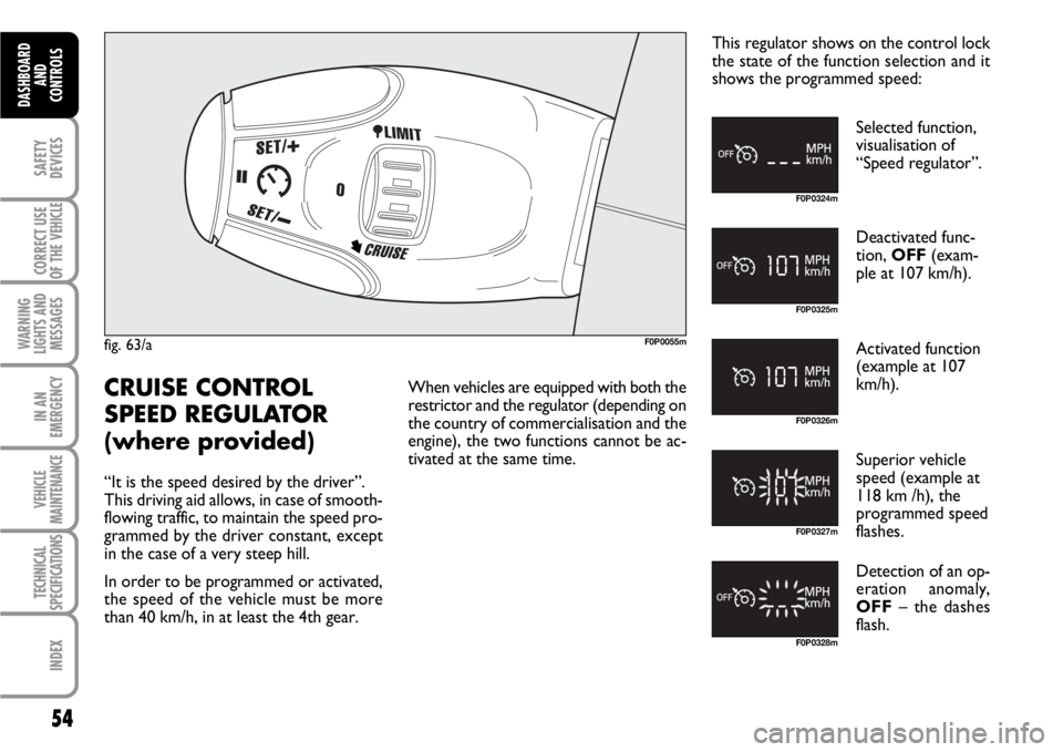
fig. 63/aF0P0055m
F0P0324m
F0P0325m
F0P0326m
F0P0327m
F0P0328m
CRUISE CONTROL
SPEED REGULATOR
(where provided)
“It is the speed desired by the driver”.
This driving aid allows, in case of smooth-
flowing traffic, to maintain the speed pro-
grammed by the driver constant, except
in the case of a very steep hill.
In order to be programmed or activated,
the speed of the vehicle must be more
than 40 km/h, in at least the 4th gear.When vehicles are equipped with both the
restrictor and the regulator (depending on
the country of commercialisation and the
engine), the two functions cannot be ac-
tivated at the same time.This regulator shows on the control lock
the state of the function selection and it
shows the programmed speed:
Selected function,
visualisation of
“Speed regulator”.
Deactivated func-
tion, OFF(exam-
ple at 107 km/h).
Activated function
(example at 107
km/h).
Superior vehicle
speed (example at
118 km /h), the
programmed speed
flashes.
Detection of an op-
eration anomaly,
OFF– the dashes
flash.
Page 56 of 210
55
SAFETY
DEVICES
CORRECT USE
OF THE
VEHICLE
WARNING
LIGHTS AND
MESSAGES
IN AN
EMERGENCY
VEHICLE
MAINTENANCE
TECHNICAL
SPECIFICATIONS
INDEX
DASHBOARD
AND CONTROLS
F0P0329m F0P0324m
F0P0330m F0P0331m
F0P0333m F0P0327mF0P0334m F0P0331m
F0P0334m F0P0325m
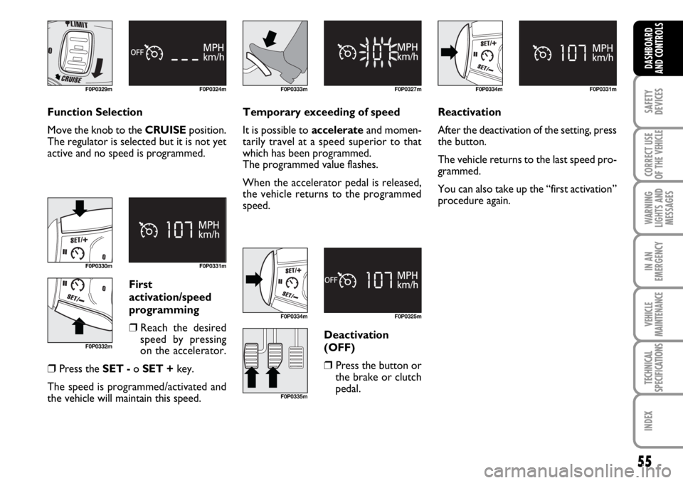
Function Selection
Move the knob to the CRUISEposition.
The regulator is selected but it is not yet
active and no speed is programmed.Temporary exceeding of speed
It is possible to accelerateand momen-
tarily travel at a speed superior to that
which has been programmed.
The programmed value flashes.
When the accelerator pedal is released,
the vehicle returns to the programmed
speed.
First
activation/speed
programming
❒Reach the desired
speed by pressing
on the accelerator.
❒Press the SET -o SET +key.
The speed is programmed/activated and
the vehicle will maintain this speed.Deactivation
(OFF)❒Press the button or
the brake or clutch
pedal.Reactivation
After the deactivation of the setting, press
the button.
The vehicle returns to the last speed pro-
grammed.
You can also take up the “first activation”
procedure again.
F0P0332m
F0P0335m
Page 57 of 210
56
SAFETY
DEVICES
CORRECT USE
OF THE
VEHICLE
WARNING
LIGHTS AND
MESSAGES
IN AN
EMERGENCY
VEHICLE
MAINTENANCE
TECHNICAL
SPECIFICATIONS
INDEX
DASHBOARD
AND
CONTROLS
F0P0330m F0P0336mF0P0337m F0P0325m
F0P0328m
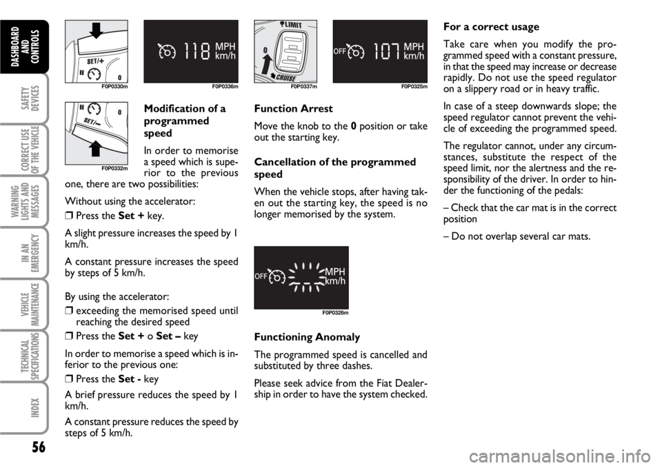
Modification of a
programmed
speed
In order to memorise
a speed which is supe-
rior to the previous
one, there are two possibilities:
Without using the accelerator:
❒Press the Set +key.
A slight pressure increases the speed by 1
km/h.
A constant pressure increases the speed
by steps of 5 km/h.
By using the accelerator:
❒exceeding the memorised speed until
reaching the desired speed
❒Press the Set + o Set –key
In order to memorise a speed which is in-
ferior to the previous one:
❒Press the Set -key
A brief pressure reduces the speed by 1
km/h.
A constant pressure reduces the speed by
steps of 5 km/h.Function Arrest
Move the knob to the 0position or take
out the starting key.
Cancellation of the programmed
speed
When the vehicle stops, after having tak-
en out the starting key, the speed is no
longer memorised by the system.
Functioning Anomaly
The programmed speed is cancelled and
substituted by three dashes.
Please seek advice from the Fiat Dealer-
ship in order to have the system checked.For a correct usage
Take care when you modify the pro-
grammed speed with a constant pressure,
in that the speed may increase or decrease
rapidly. Do not use the speed regulator
on a slippery road or in heavy traffic.
In case of a steep downwards slope; the
speed regulator cannot prevent the vehi-
cle of exceeding the programmed speed.
The regulator cannot, under any circum-
stances, substitute the respect of the
speed limit, nor the alertness and the re-
sponsibility of the driver. In order to hin-
der the functioning of the pedals:
– Check that the car mat is in the correct
position
– Do not overlap several car mats.
F0P0332m
Page 58 of 210
57
SAFETY
DEVICES
CORRECT USE
OF THE
VEHICLE
WARNING
LIGHTS AND
MESSAGES
IN AN
EMERGENCY
VEHICLE
MAINTENANCE
TECHNICAL
SPECIFICATIONS
INDEX
DASHBOARD
AND CONTROLS
F0P0055m
F0P0338m
F0P0339m
F0P0340m
F0P0341m
F0P0342m
“LIMIT” SPEED
RESTRICTOR
(where provided)
“It is the chosen speed which the driver
does not wish to exceed”. This selection
can be made when the engine is running,
when the vehicle is stationary or in gear.
The minimum speed which can be pro-
grammed is 30 km/h.
The speed of the vehicle answers to the
pressure of the driver’s foot until the re-
sistance point of the accelerator pedal, to
indicate that the programmed speed has
been reached. However, the pressure on
the accelerator pedal beyond this point of
resistance allows the programmed speed
to be exceeded.To recover the use of the restrictor, it is
sufficient to progressively release the pres-
sure on the accelerator pedal and return
below the programmed speed.
In vehicles equipped with speed restric-
tors and regulators (depending on the
country of commercialisation and the en-
gine), the two functions cannot be acti-
vated at the same time.
The manipulations can be carried out both
when the vehicle is stationary and when
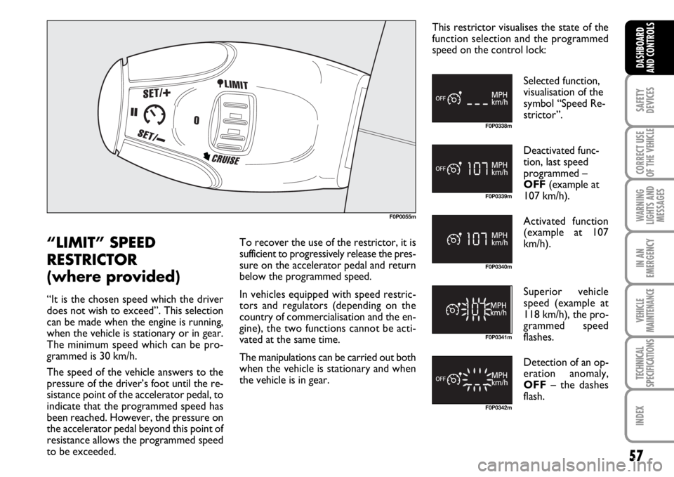
the vehicle is in gear.This restrictor visualises the state of the
function selection and the programmed
speed on the control lock:
Selected function,
visualisation of the
symbol “Speed Re-
strictor”.
Deactivated func-
tion, last speed
programmed –
OFF(example at
107 km/h).
Activated function
(example at 107
km/h).
Superior vehicle
speed (example at
118 km/h), the pro-
grammed speed
flashes.
Detection of an op-
eration anomaly,
OFF– the dashes
flash.
Page 59 of 210

58
SAFETY
DEVICES
CORRECT USE
OF THE
VEHICLE
WARNING
LIGHTS AND
MESSAGES
IN AN
EMERGENCY
VEHICLE
MAINTENANCE
TECHNICAL
SPECIFICATIONS
INDEX
DASHBOARD
AND
CONTROLS
F0P0343m F0P0338mF0P0330m
F0P0332mF0P0344m F0P0351m
F0P0334m
F0P0334mF0P0339m F0P0340m
Function Selection
Position the knob at the LIMITposition.
The restrictor is selected but it is not yet
active. The display indicates the last speed
programmed.
Speed Programming
This programming function can be carried
out without activating the restrictor, but
with the engine running.
In order to memorise a speed superior to
the previous one:
❒press the Set +key.
A slight pressure increases the speed by 1
km/h.
A constant pressure increases the speed
by steps of 5 km/h.
In order to memorise a speed less than
the previous one:
❒press the Set -key.
A slight pressure reduces the speed by 1
km/h.
A constant pressure reduces the speed by
steps of 5 km/h. Activation/deactivation (OFF)
By pressing the button the first time, it ac-
tivates the restrictor; a second time de-
activates it (OFF).
Page 60 of 210
59
SAFETY
DEVICES
CORRECT USE
OF THE
VEHICLE
WARNING
LIGHTS AND
MESSAGES
IN AN
EMERGENCY
VEHICLE
MAINTENANCE
TECHNICAL
SPECIFICATIONS
INDEX
DASHBOARD
AND CONTROLS
F0P0333m F0P0341mF0P0345m F0P0339mF0P0342m
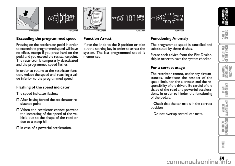
Exceeding the programmed speed
Pressing on the accelerator pedal in order
to exceed the programmed speed will have
no effect, except if you press hard on the
pedal and you exceed the resistance point.
The restrictor is temporarily deactivated
and the programmed speed flashes.
In order to return to the restrictor func-
tion, reduce the speed until reaching a val-
ue inferior to the programmed speed.
Flashing of the speed indicator
The speed indicator flashes:
❒After having forced the accelerator re-
sistance point
❒When the restrictor cannot prevent
the increasing of the speed of the ve-
hicle due to the shape of the road or
due to a steep hill
❒In case of a powerful acceleration.Function Arrest
Move the knob to the 0position or take
out the starting key in order to arrest the
system. The last programmed speed is
memorised.Functioning Anomaly
The programmed speed is cancelled and
substituted by three dashes.
Please seek advice from the Fiat Dealer-
ship in order to have the system checked.
For a correct usage
The restrictor cannot, under any circum-
stances, substitute the respect of the
speed limit, nor the alertness and the re-
sponsibility of the driver. Be careful of the
shape of the road and powerful accelera-
tions. In order to hinder the functioning
of the pedals:
– Check that the car mat is in the correct
position
– Do not overlap several car mats.
Page 61 of 210
60
SAFETY
DEVICES
CORRECT USE
OF THE
VEHICLE
WARNING
LIGHTS AND
MESSAGES
IN AN
EMERGENCY
VEHICLE
MAINTENANCE
TECHNICAL
SPECIFICATIONS
INDEX
DASHBOARD
AND
CONTROLS
CEILING LIGHTS
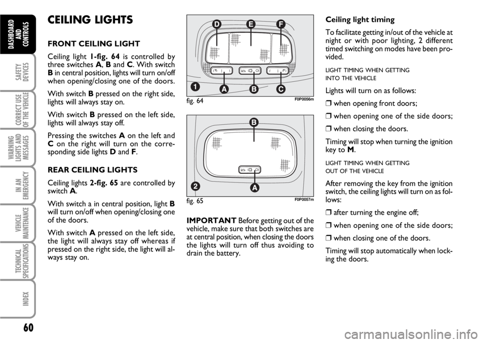
FRONT CEILING LIGHT
Ceiling light 1-fig. 64is controlled by
three switches A, Band C. With switch
Bin central position, lights will turn on/off
when opening/closing one of the doors.
With switch Bpressed on the right side,
lights will always stay on.
With switch Bpressed on the left side,
lights will always stay off.
Pressing the switches Aon the left and
Con the right will turn on the corre-
sponding side lights Dand F.
REAR CEILING LIGHTS
Ceiling lights 2-fig. 65are controlled by
switch A.
With switch a in central position, light B
will turn on/off when opening/closing one
of the doors.
With switch Apressed on the left side,
the light will always stay off whereas if
pressed on the right side, the light will al-
ways stay on.IMPORTANTBefore getting out of the
vehicle, make sure that both switches are
at central position, when closing the doors
the lights will turn off thus avoiding to
drain the battery.
fig. 65F0P0057m
Ceiling light timing
To facilitate getting in/out of the vehicle at
night or with poor lighting, 2 different
timed switching on modes have been pro-
vided.
LIGHT TIMING WHEN GETTING
INTO THE VEHICLE
Lights will turn on as follows:
❒when opening front doors;
❒when opening one of the side doors;
❒when closing the doors.
Timing will stop when turning the ignition
key to M.
LIGHT TIMING WHEN GETTING
OUT OF THE VEHICLE
After removing the key from the ignition
switch, the ceiling lights will turn on as fol-
lows:
❒after turning the engine off;
❒when opening one of the side doors;
❒when closing one of the doors.
Timing will stop automatically when lock-
ing the doors.
fig. 64F0P0056m
Page 62 of 210
61
SAFETY
DEVICES
CORRECT USE
OF THE
VEHICLE
WARNING
LIGHTS AND
MESSAGES
IN AN
EMERGENCY
VEHICLE
MAINTENANCE
TECHNICAL
SPECIFICATIONS
INDEX
DASHBOARD
AND CONTROLS
fig. 66F0P0287m
CONTROLS
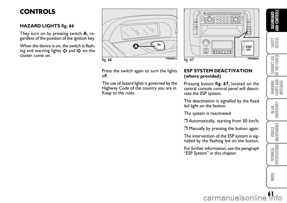
HAZARD LIGHTS fig. 66
They turn on by pressing switch A, re-
gardless of the position of the ignition key.
When the device is on, the switch is flash-
ing and warning lights
Îand ¥on the
cluster come on.
ESP SYSTEM DEACTIVATION
(where provided)
Pressing button fig. 67, located on the
central console control panel will deacti-
vate the ESP system.
The deactivation is signalled by the fixed
led light on the button.
The system is reactivated:
❒Automatically, starting from 50 km/h;
❒Manually by pressing the button again.
The intervention of the ESP system is sig-
nalled by the flashing led on the button.
For further information, see the paragraph
“ESP System” in this chapter.
fig. 67F0P0064m
Press the switch again to turn the lights
off.
The use of hazard lights is governed by the
Highway Code of the country you are in.
Keep to the rules.
Page 63 of 210
62
SAFETY
DEVICES
CORRECT USE
OF THE
VEHICLE
WARNING
LIGHTS AND
MESSAGES
IN AN
EMERGENCY
VEHICLE
MAINTENANCE
TECHNICAL
SPECIFICATIONS
INDEX
DASHBOARD
AND
CONTROLS
HEATED REAR WINDOW
(where provided)
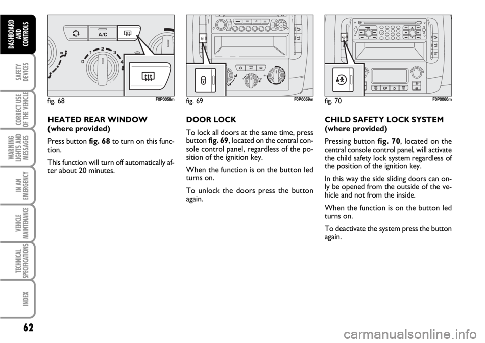
Press button fig. 68to turn on this func-
tion.
This function will turn off automatically af-
ter about 20 minutes.DOOR LOCK
To lock all doors at the same time, press
button fig. 69, located on the central con-
sole control panel, regardless of the po-
sition of the ignition key.
When the function is on the button led
turns on.
To unlock the doors press the button
again.CHILD SAFETY LOCK SYSTEM
(where provided)
Pressing button fig. 70, located on the
central console control panel, will activate
the child safety lock system regardless of
the position of the ignition key.
In this way the side sliding doors can on-
ly be opened from the outside of the ve-
hicle and not from the inside.
When the function is on the button led
turns on.
To deactivate the system press the button
again.
fig. 68F0P0058mfig. 69F0P0059mfig. 70F0P0060m
Page 64 of 210
63
SAFETY
DEVICES
CORRECT USE
OF THE
VEHICLE
WARNING
LIGHTS AND
MESSAGES
IN AN
EMERGENCY
VEHICLE
MAINTENANCE
TECHNICAL
SPECIFICATIONS
INDEX
DASHBOARD
AND CONTROLS
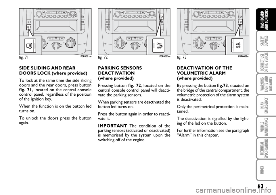
DEACTIVATION OF THE
VOLUMETRIC ALARM
(where provided)
By pressing the button fig.73, situated on
the bridge of the central compartment, the
volumetric protection of the alarm system
is deactivated.
Only the perimetrical protection is main-
tained.
The deactivation is signalled by the light-
ing of the led on the button.
For further information see the paragraph
“Alarm” in this chapter.
fig. 72F0P0063m
PARKING SENSORS
DEACTIVATION
(where provided)
Pressing button fig. 72, located on the
central console control panel will deacti-
vate the parking sensors.
When parking sensors are deactivated the
button led turns on.
Press the button again in order to reacti-
vate it.
IMPORTANTThe condition of the
parking sensors (activated or deactivated)
is memorised by the system upon the
switching off of the engine.
fig. 73F0P0062m
SIDE SLIDING AND REAR
DOORS LOCK (where provided)
To lock at the same time the side sliding
doors and the rear doors, press button
fig. 71, located on the central console
control panel, regardless of the position
of the ignition key.
When the function is on the button led
turns on.
To unlock the doors press the button
again.
fig. 71F0P0061m