technical specifications FIAT SCUDO 2010 Owner handbook (in English)
[x] Cancel search | Manufacturer: FIAT, Model Year: 2010, Model line: SCUDO, Model: FIAT SCUDO 2010Pages: 210, PDF Size: 3.32 MB
Page 75 of 210
74
SAFETY
DEVICES
CORRECT USE
OF THE
VEHICLE
WARNING
LIGHTS AND
MESSAGES
IN AN
EMERGENCY
VEHICLE
MAINTENANCE
TECHNICAL
SPECIFICATIONS
INDEX
DASHBOARD
AND
CONTROLS
POWER
WINDOWS/WINDOW
WINDERS
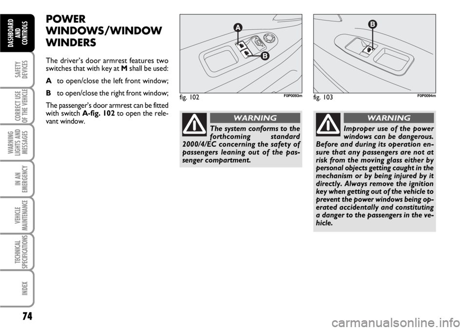
The driver’s door armrest features two
switches that with key at Mshall be used:
Ato open/close the left front window;
Bto open/close the right front window;
The passenger’s door armrest can be fitted
with switch A-fig. 102to open the rele-
vant window.
fig. 102F0P0093mfig. 103F0P0094m
Improper use of the power
windows can be dangerous.
Before and during its operation en-
sure that any passengers are not at
risk from the moving glass either by
personal objects getting caught in the
mechanism or by being injured by it
directly. Always remove the ignition
key when getting out of the vehicle to
prevent the power windows being op-
erated accidentally and constituting
a danger to the passengers in the ve-
hicle.
WARNING
The system conforms to the
forthcoming standard
2000/4/EC concerning the safety of
passengers leaning out of the pas-
senger compartment.
WARNING
Page 76 of 210

75
SAFETY
DEVICES
CORRECT USE
OF THE
VEHICLE
WARNING
LIGHTS AND
MESSAGES
IN AN
EMERGENCY
VEHICLE
MAINTENANCE
TECHNICAL
SPECIFICATIONS
INDEX
DASHBOARD
AND CONTROLS
FUNCTIONING
Manual operation
Press the button or pull it, without going
beyond the resistance point. The window
stops as soon as the command is released.
Automatic Operation
Press the button or pull it, beyond the re-
sistance point. The window opens or clos-
es completely after having released the
command: a new impulse stops the win-
dow movement.
The electrical functions of the window
winder are deactivated:
– Approx. 45 seconds after the key is tak-
en out of the switch.
– After the opening of one of the rear
doors, with the key taken out.ANTI-CRUSHING SAFETY
SYSTEM
If the vehicle is equipped with this system,
when the window rises and it meets with
an obstacle, it stops and it slightly lowers.
In case of a sudden opening of the window
upon closure, press the button until it is
completely open. Within 4 seconds, pull
the button until the window is complete-
ly closed.
During these operations, the safety sys-
tem is not active.Re-initialise of the anti-crushing
system
After a disconnection of the battery, it is
necessary to re-initialise the safety func-
tion.
Let the window lower completely and
then let it rise. It will progressively rise, a
few centimetres upon each pressure of
the button. Repeat the operation until the
window is completely open.
Keep the command pressed for at least a
second after the complete closure of the
window.
During these operations, the safety sys-
tem is not active.
Page 77 of 210
76
SAFETY
DEVICES
CORRECT USE
OF THE
VEHICLE
WARNING
LIGHTS AND
MESSAGES
IN AN
EMERGENCY
VEHICLE
MAINTENANCE
TECHNICAL
SPECIFICATIONS
INDEX
DASHBOARD
AND
CONTROLS
BONNET
IMPORTANT Before opening the bonnet,
check that windscreen wiper arms are not
lifted from the windscreen.
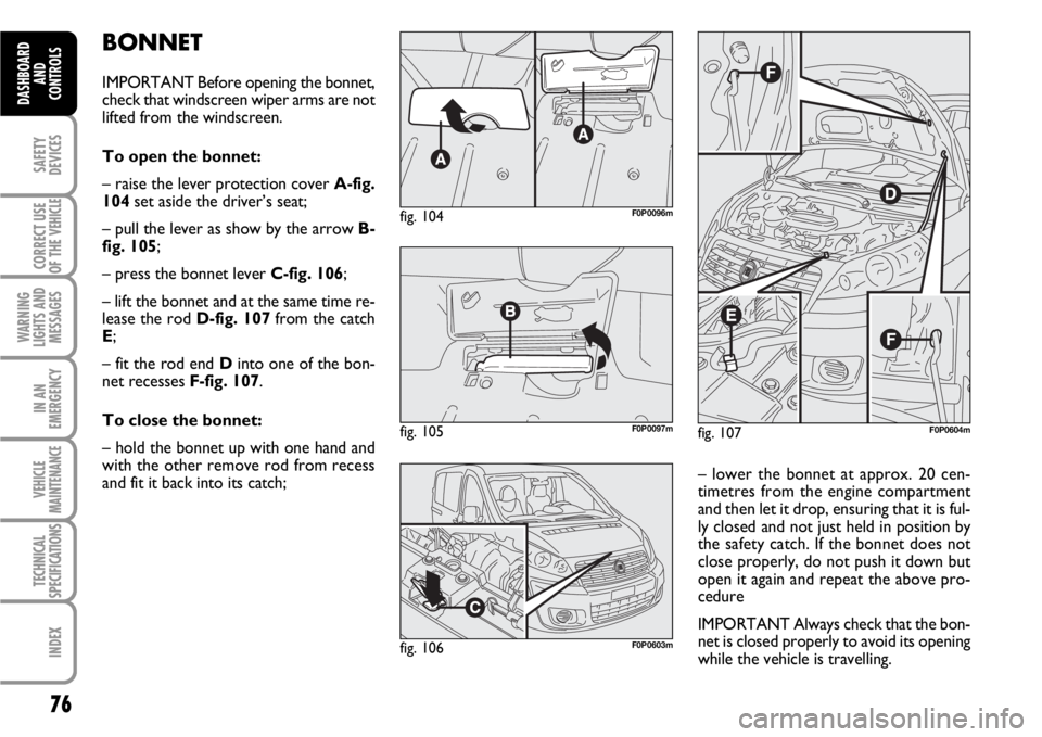
To open the bonnet:
– raise the lever protection cover A-fig.
104set aside the driver’s seat;
– pull the lever as show by the arrow B-
fig. 105;
– press the bonnet lever C-fig. 106;
– lift the bonnet and at the same time re-
lease the rod D-fig. 107from the catch
E;
– fit the rod end Dinto one of the bon-
net recesses F-fig. 107.
To close the bonnet:
– hold the bonnet up with one hand and
with the other remove rod from recess
and fit it back into its catch;
fig. 107F0P0604m
– lower the bonnet at approx. 20 cen-
timetres from the engine compartment
and then let it drop, ensuring that it is ful-
ly closed and not just held in position by
the safety catch. If the bonnet does not
close properly, do not push it down but
open it again and repeat the above pro-
cedure
IMPORTANT Always check that the bon-
net is closed properly to avoid its opening
while the vehicle is travelling.
fig. 104F0P0096m
fig. 105F0P0097m
fig. 106F0P0603m
Page 78 of 210
77
SAFETY
DEVICES
CORRECT USE
OF THE
VEHICLE
WARNING
LIGHTS AND
MESSAGES
IN AN
EMERGENCY
VEHICLE
MAINTENANCE
TECHNICAL
SPECIFICATIONS
INDEX
DASHBOARD
AND CONTROLS
ROOF RACK/SKI RACK
PRESETTING
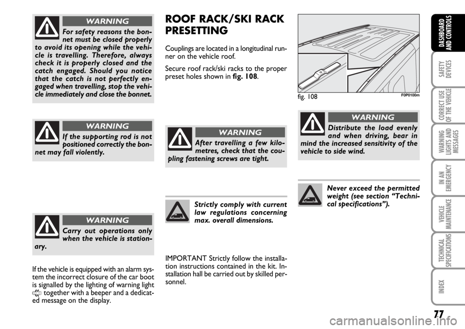
Couplings are located in a longitudinal run-
ner on the vehicle roof.
Secure roof rack/ski racks to the proper
preset holes shown in fig. 108.
IMPORTANT Strictly follow the installa-
tion instructions contained in the kit. In-
stallation hall be carried out by skilled per-
sonnel.
fig. 108F0P0100m
After travelling a few kilo-
metres, check that the cou-
pling fastening screws are tight.
WARNING
Strictly comply with current
law regulations concerning
max. overall dimensions.
Distribute the load evenly
and when driving, bear in
mind the increased sensitivity of the
vehicle to side wind.
WARNING
Never exceed the permitted
weight (see section “Techni-
cal specifications”).
For safety reasons the bon-
net must be closed properly
to avoid its opening while the vehi-
cle is travelling. Therefore, always
check it is properly closed and the
catch engaged. Should you notice
that the catch is not perfectly en-
gaged when travelling, stop the vehi-
cle immediately and close the bonnet.
WARNING
If the supporting rod is not
positioned correctly the bon-
net may fall violently.
WARNING
Carry out operations only
when the vehicle is station-
ary.
WARNING
If the vehicle is equipped with an alarm sys-
tem the incorrect closure of the car boot
is signalled by the lighting of warning light
9together with a beeper and a dedicat-
ed message on the display.
Page 79 of 210
78
SAFETY
DEVICES
CORRECT USE
OF THE
VEHICLE
WARNING
LIGHTS AND
MESSAGES
IN AN
EMERGENCY
VEHICLE
MAINTENANCE
TECHNICAL
SPECIFICATIONS
INDEX
DASHBOARD
AND
CONTROLS
PNEUMATIC
SUSPENSIONS
In some versions the tires rear suspen-
sions self-leveling may be included as an
optional.
According to versions suspensions can be
adjusted manually or automatically.
MANUAL ADJUSTMENT
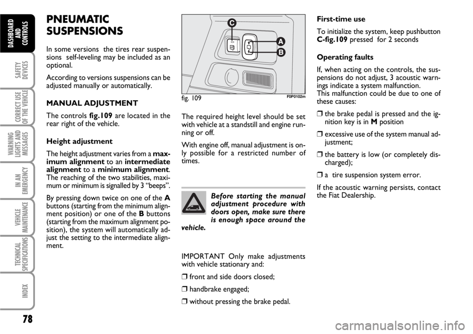
The controls fig.109are located in the
rear right of the vehicle.
Height adjustment
The height adjustment varies from a max-
imum alignmentto an intermediate
alignmentto a minimum alignment.
The reaching of the two stabilities, maxi-
mum or minimum is signalled by 3 “beeps”.
By pressing down twice on one of the A
buttons (starting from the minimum align-
ment position) or one of the Bbuttons
(starting from the maximum alignment po-
sition), the system will automatically ad-
just the setting to the intermediate align-
ment.
fig. 109F0P0102m
Before starting the manual
adjustment procedure with
doors open, make sure there
is enough space around the
vehicle.
First-time use
To initialize the system, keep pushbutton
C-fig.109pressed for 2 seconds
Operating faults
If, when acting on the controls, the sus-
pensions do not adjust, 3 acoustic warn-
ings indicate a system malfunction.
This malfunction could be due to one of
these causes:
❒the brake pedal is pressed and the ig-
nition key is in Mposition
❒excessive use of the system manual ad-
justment;
❒the battery is low (or completely dis-
charged);
❒a tire suspension system error.
If the acoustic warning persists, contact
the Fiat Dealership. The required height level should be set
with vehicle at a standstill and engine run-
ning or off.
With engine off, manual adjustment is on-
ly possible for a restricted number of
times.
IMPORTANT Only make adjustments
with vehicle stationary and:
❒front and side doors closed;
❒handbrake engaged;
❒without pressing the brake pedal.
Page 80 of 210
79
SAFETY
DEVICES
CORRECT USE
OF THE
VEHICLE
WARNING
LIGHTS AND
MESSAGES
IN AN
EMERGENCY
VEHICLE
MAINTENANCE
TECHNICAL
SPECIFICATIONS
INDEX
DASHBOARD
AND CONTROLS
AUTOMATIC ADJUSTMENT
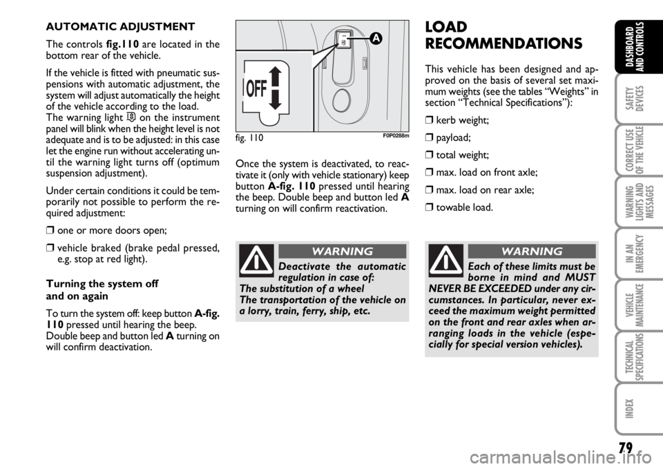
The controls fig.110are located in the
bottom rear of the vehicle.
If the vehicle is fitted with pneumatic sus-
pensions with automatic adjustment, the
system will adjust automatically the height
of the vehicle according to the load.
The warning light
…on the instrument
panel will blink when the height level is not
adequate and is to be adjusted: in this case
let the engine run without accelerating un-
til the warning light turns off (optimum
suspension adjustment).
Under certain conditions it could be tem-
porarily not possible to perform the re-
quired adjustment:
❒one or more doors open;
❒vehicle braked (brake pedal pressed,
e.g. stop at red light).
Turning the system off
and on again
To turn the system off: keep button A-fig.
110pressed until hearing the beep.
Double beep and button led Aturning on
will confirm deactivation.Once the system is deactivated, to reac-
tivate it (only with vehicle stationary) keep
button A-fig. 110pressed until hearing
the beep. Double beep and button led A
turning on will confirm reactivation.
fig. 110F0P0288m
LOAD
RECOMMENDATIONS
This vehicle has been designed and ap-
proved on the basis of several set maxi-
mum weights (see the tables “Weights” in
section “Technical Specifications”):
❒kerb weight;
❒payload;
❒total weight;
❒max. load on front axle;
❒max. load on rear axle;
❒towable load.
Each of these limits must be
borne in mind and MUST
NEVER BE EXCEEDED under any cir-
cumstances. In particular, never ex-
ceed the maximum weight permitted
on the front and rear axles when ar-
ranging loads in the vehicle (espe-
cially for special version vehicles).
WARNING
Deactivate the automatic
regulation in case of:
The substitution of a wheel
The transportation of the vehicle on
a lorry, train, ferry, ship, etc.
WARNING
Page 81 of 210
80
SAFETY
DEVICES
CORRECT USE
OF THE
VEHICLE
WARNING
LIGHTS AND
MESSAGES
IN AN
EMERGENCY
VEHICLE
MAINTENANCE
TECHNICAL
SPECIFICATIONS
INDEX
DASHBOARD
AND
CONTROLS
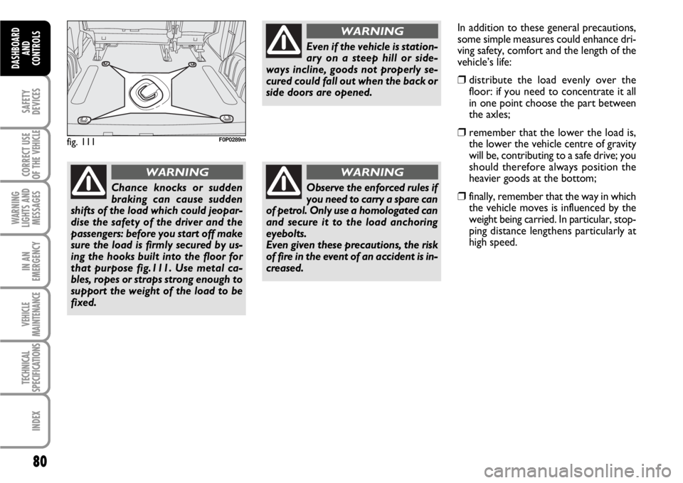
fig. 111F0P0289m
Chance knocks or sudden
braking can cause sudden
shifts of the load which could jeopar-
dise the safety of the driver and the
passengers: before you start off make
sure the load is firmly secured by us-
ing the hooks built into the floor for
that purpose fig.111. Use metal ca-
bles, ropes or straps strong enough to
support the weight of the load to be
fixed.
WARNING
Even if the vehicle is station-
ary on a steep hill or side-
ways incline, goods not properly se-
cured could fall out when the back or
side doors are opened.
WARNING
Observe the enforced rules if
you need to carry a spare can
of petrol. Only use a homologated can
and secure it to the load anchoring
eyebolts.
Even given these precautions, the risk
of fire in the event of an accident is in-
creased.
WARNING
In addition to these general precautions,
some simple measures could enhance dri-
ving safety, comfort and the length of the
vehicle’s life:
❒distribute the load evenly over the
floor: if you need to concentrate it all
in one point choose the part between
the axles;
❒remember that the lower the load is,
the lower the vehicle centre of gravity
will be, contributing to a safe drive; you
should therefore always position the
heavier goods at the bottom;
❒finally, remember that the way in which
the vehicle moves is influenced by the
weight being carried. In particular, stop-
ping distance lengthens particularly at
high speed.
Page 82 of 210
81
SAFETY
DEVICES
CORRECT USE
OF THE
VEHICLE
WARNING
LIGHTS AND
MESSAGES
IN AN
EMERGENCY
VEHICLE
MAINTENANCE
TECHNICAL
SPECIFICATIONS
INDEX
DASHBOARD
AND CONTROLS
HEADLIGHTS
ADJUSTING THE HEADLIGHT
BEAM
Proper adjustment of the headlight beams
is of vital importance for your safety and
comfort and also for the other road users.
To ensure you and other drivers have the
best visibility conditions when travelling
with the headlights on, the headlights must
be set properly. Contact Fiat Dealership
to have the headlights properly adjusted.HEADLIGHT AIMING DEVICE
It works with ignition key at Mand dipped
beams on. When the vehicle is loaded, it
slopes backwards. This means that the
headlight beam rises. In this case, it is nec-
essary to return it to the correct position.To adjust the headlight slant
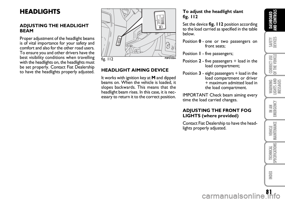
fig. 112
Set the device fig. 112position according
to the load carried as specified in the table
below.
Position 0- one or two passengers on
front seats;
Position 1- five passengers;
Position 2- five passengers + load in the
load compartment;
Position 3- eight passengers + load in the
load compartment or driver
+ maximum admitted load in
the load compartment.
IMPORTANT Check beam aiming every
time the load carried changes.
ADJUSTING THE FRONT FOG
LIGHTS (where provided)
Contact Fiat Dealership to have the head-
lights properly adjusted.
fig. 112F0F0103m
Page 83 of 210
82
SAFETY
DEVICES
CORRECT USE
OF THE
VEHICLE
WARNING
LIGHTS AND
MESSAGES
IN AN
EMERGENCY
VEHICLE
MAINTENANCE
TECHNICAL
SPECIFICATIONS
INDEX
DASHBOARD
AND CONTROLS
ADJUSTING THE
HEADLIGHT BEAM
Proper adjustment of the headlight beams
is of vital importance for your safety and
comfort and also for the other road users.
In addition it is the subject of a precise reg-
ulation of the traffic code.
To ensure you and other drivers have the
best visibility conditions when travelling
with the headlights on, the headlights must
be set properly.
Contact Fiat Dealership to have the head-
lights properly adjusted.ABS SYSTEM
If you have never driven a vehicle with ABS
before, you should practice using the sys-
tem on slippery terrain, obviously with the
necessary safety precautions and keeping
to the Highway Code of the country you
are in. It is also a good idea to read the fol-
lowing information carefully.
The ABS system, integral with the braking
system, prevents the wheels from locking
when braking, makes the most of road grip
and gives the best control when emergency
braking under difficult road conditions.
System is completed by EBD (Electronic
Braking force Distribution), which dis-
tributes the braking action between front
and rear wheels.
IMPORTANT To have the maximum ef-
ficiency of the braking system, it is neces-
sary a setting period of about 500 km
(with new vehicle or after replacing brake
pads/discs): during this period it is better
to avoid sharp, repeated and prolonged
brakes.The ABS exploits the tyre-
road grip at the best, but it
cannot improve it; you should there-
fore take every care when driving on
slippery surfaces without taking un-
necessary risks.
WARNING
ABS SYSTEM INTERVENTION
The driver can tell the ABS system has
come into action because the brake pedal
pulsates slightly and the system gets noisi-
er: it means that the vehicle speed should
be altered to fit the type of road surface.
If the ABS system cuts in, it
is a sign that the grip be-
tween tyre and the road surface has
reached the limit: you must slow
down to match the speed to the road
grip available.
WARNING
Page 84 of 210
83
SAFETY
DEVICES
CORRECT USE
OF THE
VEHICLE
WARNING
LIGHTS AND
MESSAGES
IN AN
EMERGENCY
VEHICLE
MAINTENANCE
TECHNICAL
SPECIFICATIONS
INDEX
DASHBOARD
AND CONTROLS
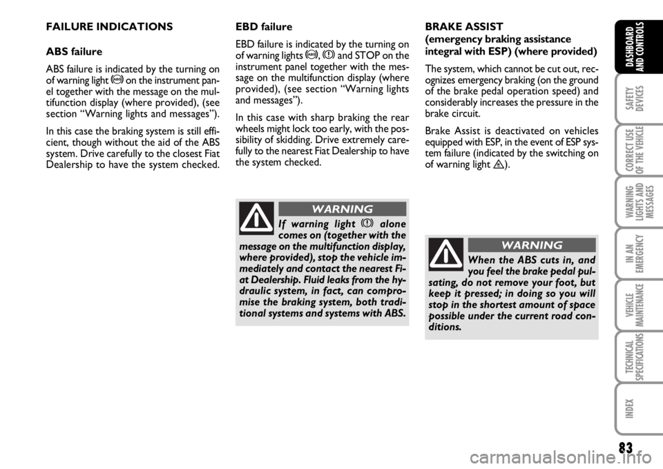
FAILURE INDICATIONS
ABS failure
ABS failure is indicated by the turning on
of warning light
>on the instrument pan-
el together with the message on the mul-
tifunction display (where provided), (see
section “Warning lights and messages”).
In this case the braking system is still effi-
cient, though without the aid of the ABS
system. Drive carefully to the closest Fiat
Dealership to have the system checked.BRAKE ASSIST
(emergency braking assistance
integral with ESP) (where provided)
The system, which cannot be cut out, rec-
ognizes emergency braking (on the ground
of the brake pedal operation speed) and
considerably increases the pressure in the
brake circuit.
Brake Assist is deactivated on vehicles
equipped with ESP, in the event of ESP sys-
tem failure (indicated by the switching on
of warning light
™).
When the ABS cuts in, and
you feel the brake pedal pul-
sating, do not remove your foot, but
keep it pressed; in doing so you will
stop in the shortest amount of space
possible under the current road con-
ditions.
WARNING
EBD failure
EBD failure is indicated by the turning on
of warning lights
>, xand STOP on the
instrument panel together with the mes-
sage on the multifunction display (where
provided), (see section “Warning lights
and messages”).
In this case with sharp braking the rear
wheels might lock too early, with the pos-
sibility of skidding. Drive extremely care-
fully to the nearest Fiat Dealership to have
the system checked.
If warning light xalone
comes on (together with the
message on the multifunction display,
where provided), stop the vehicle im-
mediately and contact the nearest Fi-
at Dealership. Fluid leaks from the hy-
draulic system, in fact, can compro-
mise the braking system, both tradi-
tional systems and systems with ABS.
WARNING