FIAT SCUDO 2016 Owner handbook (in English)
Manufacturer: FIAT, Model Year: 2016, Model line: SCUDO, Model: FIAT SCUDO 2016Pages: 227, PDF Size: 4.46 MB
Page 21 of 227
17
SAFETY
DEVICESCORRECT USE
OF THE VEHICLE WARNING
LIGHTS AND
MESSAGESIN AN
EMERGENCYVEHICLE
MAINTENANCETECHNICAL
SPECIFICATIONSINDEX DASHBOARD
AND CONTROLS
âť’
turn the button rightwards to select the
required mode;
âť’
turn the button leftwards to stop clock
setting.
If no other setting is made, after about 30
seconds the display will show the time ac-
cording to the selected settings.
Setting the clock through the
display on the central console
Certain versions are fitted with a central
console with a display showing the time.
To set the clock consult the trip comput-
er under option “Set clock and date”.
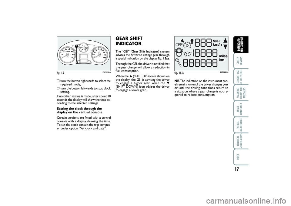
GEAR SHIFT
INDICATORThe “GSI” (Gear Shift Indicator) system
advises the driver to change gear through
a special indication on the display fig. 15/a.
Through the GSI, the driver is notified that
the gear change will allow a reduction in
fuel consumption.
When the â–˛(SHIFT UP) icon is shown on
the display, the GSI is advising the driver
to engage a higher gear, while the â–Ľ
(SHIFT DOWN) icon advises the driver
to engage a lower gear.NBThe indication on the instrument pan-
el remains on until the driver changes gear
or until the driving conditions return to
a situation where a gear change is not re-
quired to reduce consumption.
fig. 15/a
F0P0291m
fig. 15
1/2
F0P0292m
001-019 SCUDO LUM GB 27/03/14 10:10 Pagina 17
Page 22 of 227
18SAFETY
DEVICESCORRECT USE
OF THE VEHICLE
WARNING
LIGHTS AND
MESSAGESIN AN
EMERGENCYVEHICLE
MAINTENANCETECHNICAL
SPECIFICATIONSINDEXDASHBOARD
AND CONTROLS
MAINTENANCE
INDICATORIt regulates the intervals between the main-
tenance operations based on vehicle use.
Functioning
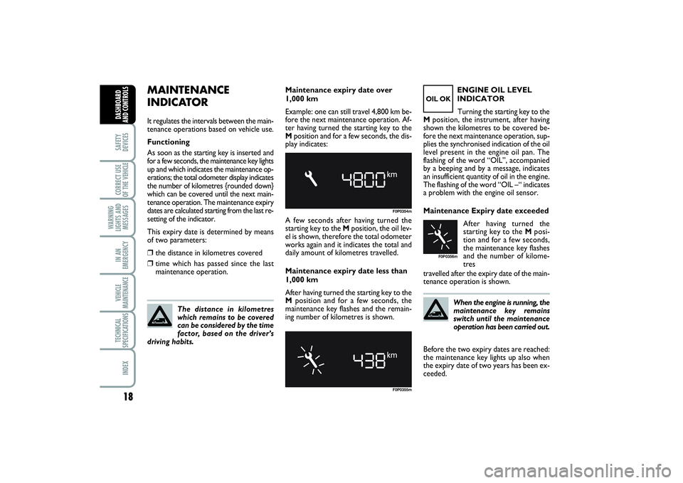
As soon as the starting key is inserted and
for a few seconds, the maintenance key lights
up and which indicates the maintenance op-
erations; the total odometer display indicates
the number of kilometres {rounded down}
which can be covered until the next main-
tenance operation. The maintenance expiry
dates are calculated starting from the last re-
setting of the indicator.
This expiry date is determined by means
of two parameters:âť’
the distance in kilometres covered
âť’
time which has passed since the last
maintenance operation.
The distance in kilometres
which remains to be covered
can be considered by the time
factor, based on the driver’s
driving habits.
F0P0354mF0P0355m
OIL OK
F0P0356m
Maintenance expiry date over
1,000 km
Example: one can still travel 4,800 km be-
fore the next maintenance operation. Af-
ter having turned the starting key to the
Mposition and for a few seconds, the dis-
play indicates:
A few seconds after having turned the
starting key to the Mposition, the oil lev-
el is shown, therefore the total odometer
works again and it indicates the total and
daily amount of kilometres travelled.
Maintenance expiry date less than
1,000 km
After having turned the starting key to the
Mposition and for a few seconds, the
maintenance key flashes and the remain-
ing number of kilometres is shown.ENGINE OIL LEVEL
INDICATOR
Turning the starting key to the
Mposition, the instrument, after having
shown the kilometres to be covered be-
fore the next maintenance operation, sup-
plies the synchronised indication of the oil
level present in the engine oil pan. The
flashing of the word “OIL”, accompanied
by a beeping and by a message, indicates
an insufficient quantity of oil in the engine.
The flashing of the word “OIL –“ indicates
a problem with the engine oil sensor.
Maintenance Expiry date exceeded
After having turned the
starting key to the Mposi-
tion and for a few seconds,
the maintenance key flashes
and the number of kilome-
tres
travelled after the expiry date of the main-
tenance operation is shown.
When the engine is running, the
maintenance key remains
switch until the maintenance
operation has been carried out.
Before the two expiry dates are reached:
the maintenance key lights up also when
the expiry date of two years has been ex-
ceeded.
001-019 SCUDO LUM GB 27/03/14 10:10 Pagina 18
Page 23 of 227
19
SAFETY
DEVICESCORRECT USE
OF THE VEHICLE WARNING
LIGHTS AND
MESSAGESIN AN
EMERGENCYVEHICLE
MAINTENANCETECHNICAL
SPECIFICATIONSINDEX DASHBOARD
AND CONTROLS
Distance to cover
This value shows the distance to be cov-
ered yet, under active navigation condi-
tion.
Trip distance
This value shows the distance covered
from the start of the journey, after reset-
ting (Reset).
Average consumption
This value shows the average consump-
tion from the start of the journey, after
resetting (Reset).
Average speed
This value shows the vehicle average
speed calculated from the start of the
journey, after resetting (Reset).
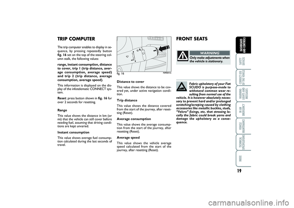
TRIP COMPUTERThe trip computer enables to display in se-
quence, by pressing repeatedly button
fig. 16set on the top of the steering col-
umn stalk, the following values:
range, instant consumption, distance
to cover, trip 1 (trip distance, aver-
age consumption, average speed)
and trip 2 (trip distance, average
consumption, average speed).
This information is displayed on the dis-
play of the infotelematic CONNECT sys-
tem.
Reset: press button shown in fig. 16for
over 2 seconds for resetting.
Range
This value shows the distance in km (or
mi) that the vehicle can still cover before
needing fuel, assuming that driving condi-
tions are kept unvaried.
Instant consumption
This value shows average fuel consump-
tion calculated during the last seconds of
travel.
fig. 16
F0P0041m
FRONT SEATS
Only make adjustments when
the vehicle is stationary.
WARNING
Fabric upholstery of your Fiat
SCUDO is purpose-made to
withstand common wear re-
sulting from normal use of the
vehicle. It is however absolutely neces-
sary to prevent hard and/or prolonged
scratching/scraping caused by clothing
accessories like metallic buckles, studs,
“Velcro” fixings, etc. that stressing lo-
cally the fabric could break yarns and
damage the upholstery as a conse-
quence.
001-019 SCUDO LUM GB 27/03/14 10:10 Pagina 19
Page 24 of 227
20SAFETY
DEVICESCORRECT USE
OF THE VEHICLE
WARNING
LIGHTS AND
MESSAGESIN AN
EMERGENCYVEHICLE
MAINTENANCETECHNICAL
SPECIFICATIONSINDEX
DASHBOARD
AND
CONTROLS
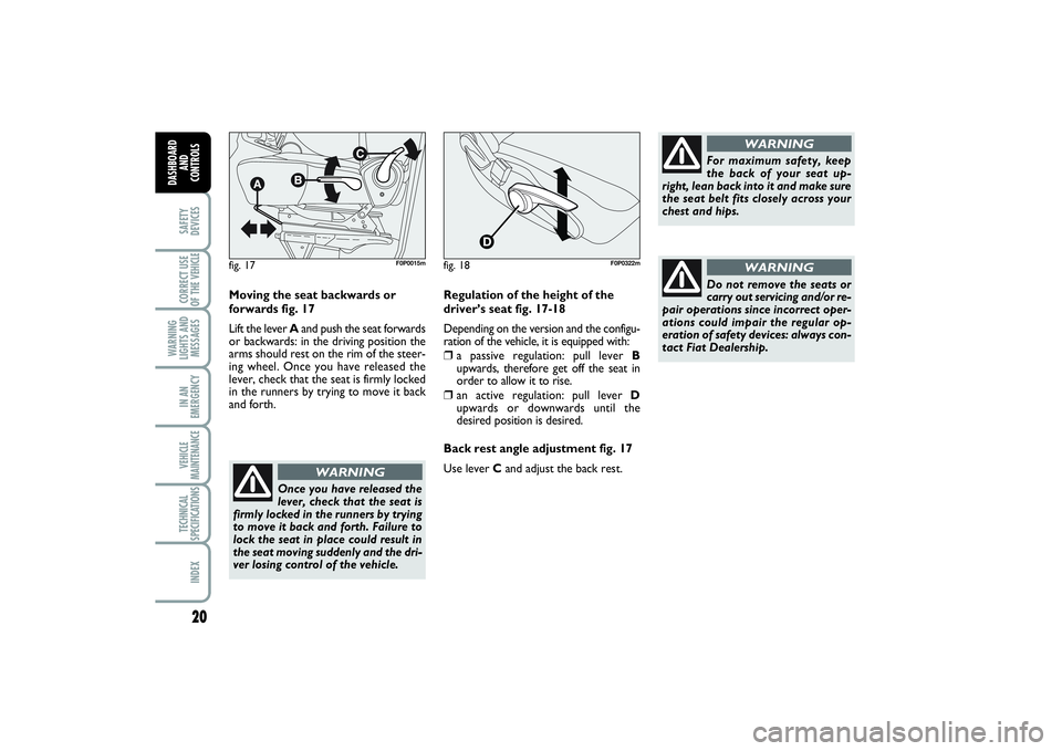
Moving the seat backwards or
forwards fig. 17
Lift the lever Aand push the seat forwards
or backwards: in the driving position the
arms should rest on the rim of the steer-
ing wheel. Once you have released the
lever, check that the seat is firmly locked
in the runners by trying to move it back
and forth.
Once you have released the
lever, check that the seat is
firmly locked in the runners by trying
to move it back and forth. Failure to
lock the seat in place could result in
the seat moving suddenly and the dri-
ver losing control of the vehicle.
WARNING
For maximum safety, keep
the back of your seat up-
right, lean back into it and make sure
the seat belt fits closely across your
chest and hips.
WARNING
Regulation of the height of the
driver’s seat fig. 17-18
Depending on the version and the configu-
ration of the vehicle, it is equipped with: âť’
a passive regulation: pull lever B
upwards, therefore get off the seat in
order to allow it to rise.
âť’
an active regulation: pull lever D
upwards or downwards until the
desired position is desired.
Back rest angle adjustment fig. 17
Use lever C and adjust the back rest.
Do not remove the seats or
carry out servicing and/or re-
pair operations since incorrect oper-
ations could impair the regular op-
eration of safety devices: always con-
tact Fiat Dealership.
WARNING
fig. 17
F0P0015m
fig. 18
F0P0322m
020-082 SCUDO LUM GB 19/11/13 09.53 Pagina 20
Page 25 of 227
21
SAFETY
DEVICESCORRECT USE
OF THE VEHICLE WARNING
LIGHTS AND
MESSAGESIN AN
EMERGENCYVEHICLE
MAINTENANCETECHNICAL
SPECIFICATIONSINDEX DASHBOARD
AND CONTROLS
fig. 18/a
F0P0016m
fig. 19A
B
F0P0017m
fig. 20
F0P0018m
fig. 21
F0P0019m
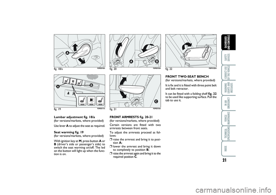
Lumbar adjustment fig. 18/a
(for versions/markets, where provided)
Use lever Ato adjust the seat as required.
Seat warming fig. 19
(for versions/markets, where provided)
With ignition key at M, press button Aor
B(driver’s side or passenger’s side) to
switch the seat warming on/off. The led
on the button will light up when the func-
tion is on.FRONT ARMRESTS fig. 20-21
(for versions/markets, where provided)
Certain versions are fitted with two
armrests between front seats.
To adjust the armrests proceed as fol-
lows:
âť’
raise the armrest and bring it to posi-
tion A;
âť’
lower the armrest and bring it down
to completely to position B;
âť’
raise the armrest again and bring it to the
required position C.
fig. 22
F0P0122m
FRONT TWO-SEAT BENCH
(for versions/markets, where provided)
It is fix and it is fitted with three point belt
and belt retractor.
It can be fitted with a folding shelf fig. 22
to be used like supporting surface. Pull the
tab to use it.
020-082 SCUDO LUM GB 19/11/13 09.53 Pagina 21
Page 26 of 227
22SAFETY
DEVICESCORRECT USE
OF THE VEHICLE
WARNING
LIGHTS AND
MESSAGESIN AN
EMERGENCYVEHICLE
MAINTENANCETECHNICAL
SPECIFICATIONSINDEX
DASHBOARD
AND
CONTROLS
FOLDING, REMOVING AND
REFITTING THE REAR BENCH
SEAT
To remove and then to re-
fit the bench seat, keep
the back rest firmly lowered and
flattened against the cushion to
prevent any contact between the
seat articulation mechanisms.
WARNING
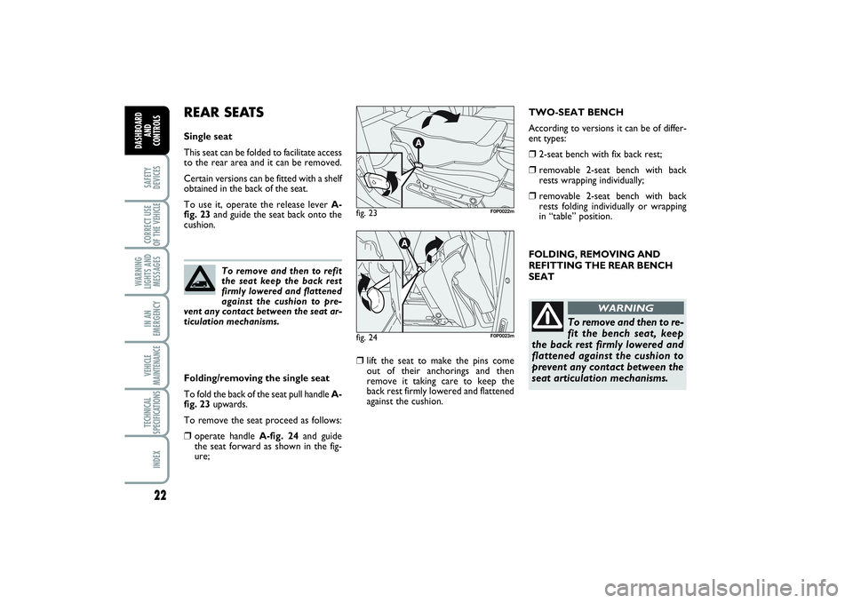
REAR SEATSSingle seat
This seat can be folded to facilitate access
to the rear area and it can be removed.
Certain versions can be fitted with a shelf
obtained in the back of the seat.
To use it, operate the release lever A-
fig. 23and guide the seat back onto the
cushion.
Folding/removing the single seat
To fold the back of the seat pull handle A-
fig. 23upwards.
To remove the seat proceed as follows:âť’
operate handle A-fig. 24and guide
the seat forward as shown in the fig-
ure;
âť’
lift the seat to make the pins come
out of their anchorings and then
remove it taking care to keep the
back rest firmly lowered and flattened
against the cushion.
fig. 23
F0P0022m
fig. 24
F0P0023m
To remove and then to refit
the seat keep the back rest
firmly lowered and flattened
against the cushion to pre-
vent any contact between the seat ar-
ticulation mechanisms.
TWO-SEAT BENCH
According to versions it can be of differ-
ent types:âť’
2-seat bench with fix back rest;
âť’
removable 2-seat bench with back
rests wrapping individually;
âť’
removable 2-seat bench with back
rests folding individually or wrapping
in “table” position.
020-082 SCUDO LUM GB 19/11/13 09.53 Pagina 22
Page 27 of 227
23
SAFETY
DEVICESCORRECT USE
OF THE VEHICLE WARNING
LIGHTS AND
MESSAGESIN AN
EMERGENCYVEHICLE
MAINTENANCETECHNICAL
SPECIFICATIONSINDEX DASHBOARD
AND CONTROLS
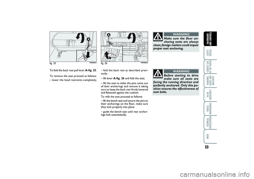
To fold the back rest pull lever A-fig. 25.
To remove the seat proceed as follows:
– lower the head restraints completely;fig. 25
F0P0024m
fig. 26
F0P0025m
– fold the back rest as described previ-
ously;
– lift leverA-fig. 26and fold the seat;
– lift the seat to make the pins come out
of their anchorings and remove it taking
care to keep the back rest firmly lowered
and flattened against the cushion.
To refit the seat proceed as follows:
– lift the bench seat and secure the pins to
their anchorings on the floor, make sure
they lock properly into place;
– guide the bench seat until rear anchor-
ings lock automatically.
Make sure the floor an-
choring seats are always
clean; foreign matters could impair
proper seat anchoring.
WARNING
Before starting to drive
make sure all seats are
facing the running direction and
perfectly anchored. Only this po-
sition ensures the effectiveness of
seat belts.
WARNING
020-082 SCUDO LUM GB 19/11/13 09.53 Pagina 23
Page 28 of 227
24SAFETY
DEVICESCORRECT USE
OF THE VEHICLE
WARNING
LIGHTS AND
MESSAGESIN AN
EMERGENCYVEHICLE
MAINTENANCETECHNICAL
SPECIFICATIONSINDEX
DASHBOARD
AND
CONTROLS
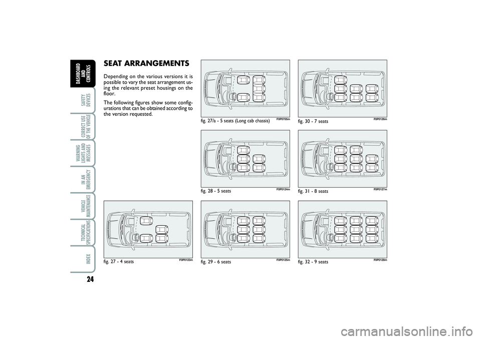
SEAT ARRANGEMENTSDepending on the various versions it is
possible to vary the seat arrangement us-
ing the relevant preset housings on the
floor.
The following figures show some config-
urations that can be obtained according to
the version requested.
F0P0705m
fig. 27/a - 5 seats (Long cab chassis)
F0P0123m
fig. 27 - 4 seats
F0P0124mF0P0125m
fig. 28 - 5 seats
fig. 29 - 6 seats
F0P0126mF0P0127mF0P0128m
fig. 30 - 7 seats
fig. 31 - 8 seats
fig. 32 - 9 seats
020-082 SCUDO LUM GB 19/11/13 09.53 Pagina 24
Page 29 of 227
25
SAFETY
DEVICESCORRECT USE
OF THE VEHICLE WARNING
LIGHTS AND
MESSAGESIN AN
EMERGENCYVEHICLE
MAINTENANCETECHNICAL
SPECIFICATIONSINDEX DASHBOARD
AND CONTROLS
HEAD RESTRAINTSTo raise:âť’
raise the head restraint until hearing the
locking click.
To lower:
âť’
press buttons A-fig. 33or A-fig. 34
and lower the head restraint.
Remember that the head re-
straints should be adjusted
to support the back of your head and
not your neck. Only in this position
do they exert their protective action
WARNING
IMPORTANT Following a different seat
layout:âť’
if you take the head rest off, replace it
ad fix it to a support
âť’
check that the safety belts are still ac-
cessible and easy for the passenger to
fasten
âť’
a passenger must never travel without
having correctly regulated the head rest
or without having regulated and fas-
tened the safety belt
âť’
in the long cab chassis versions the
bench seat of the long cab is not suit-
able for positioning a child restraint sys-
tem.
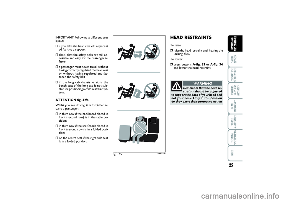
ATTENTION fig. 32/a
Whilst you are driving, it is forbidden to
carry a passenger:
âť’
in third row if the backboard placed in
front (second row) is in the table po-
sition;
âť’
in third row if the seat/coach placed in
front (second row) is in a folded posi-
tion;
âť’
on the centre seat if the right side seat
is in a folded position.
fig. 32/a
F0P0323m
020-082 SCUDO LUM GB 19/11/13 09.54 Pagina 25
Page 30 of 227
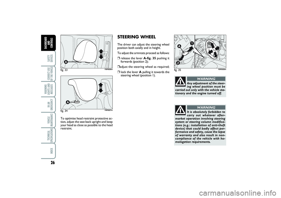
STEERING WHEELThe driver can adjust the steering wheel
position both axially and in height.
To adjust the armrests proceed as follows:âť’
release the lever A-fig. 35pushing it
forwards (position 2);
âť’adjust the steering wheel as required;âť’
lock the lever Apulling it towards the
steering wheel (position 1).
fig. 35
F0P0028m
Any adjustment of the steer-
ing wheel position must be
carried out only with the vehicle sta-
tionary and the engine turned off.
WARNING
It is absolutely forbidden to
carry out whatever after-
market operation involving steering
system or steering column modifica-
tions (e.g.: installation of anti-theft
device) that could badly affect per-
formance and safety, cause the lapse
of warranty and also result in non-
compliance of the vehicle with ho-
mologation requirements.
WARNING
26SAFETY
DEVICESCORRECT USE
OF THE VEHICLE
WARNING
LIGHTS AND
MESSAGESIN AN
EMERGENCYVEHICLE
MAINTENANCETECHNICAL
SPECIFICATIONSINDEX
DASHBOARD
AND
CONTROLS
fig. 33
F0P0026m
fig. 34
F0P0027m
To optimise head restraint protective ac-
tion, adjust the seat back upright and keep
your head as close as possible to the head
restraint.
020-082 SCUDO LUM GB 19/11/13 09.54 Pagina 26