sensor FIAT TEMPRA 1988 Service And Repair Manual
[x] Cancel search | Manufacturer: FIAT, Model Year: 1988, Model line: TEMPRA, Model: FIAT TEMPRA 1988Pages: 171, PDF Size: 18.05 MB
Page 7 of 171
Fluid levels (if included) are monitored by LEDs f, o and
p, indicating the levels of the fluid reservoirs.
A red LED illuminates at the position on the check panel
corresponding to a side door or a hatchback/tailgate
that is not properly closed.
SIDE AND TAIL LIGHTS
When the side and tail lights are turned on, the check
panel monitors the light bulbs, fuses and circuits.
• LED g monitors the front side lights.
• LED i monitors the tail lights.
If one of the two fuses protecting the following bulbs
blows, LEDs g, i, and m illuminate.
NUMBER PLATE LIGHTS
• LED m indicates when one or both of the number
plate light bulbs have burnt out.
REAR FOG LIGHTS
• When the fog-guard lights are turned on, LED h
monitors the light bulbs.
• When the fuse blows or a circuit malfunction occurs,
LED h illuminates, but not the panel indicator.
STOP LIGHTS
If one or both stop lights burn out, the fuse blows or a
circuit malfunction occurs, LED I or n illuminates when
braking.
• LED n monitors the left stop light.
• LED I monitors the right stop light.
If both bulbs burn out at the same time or brake pedal
switch malfunction occurs, both LEDs I and n
illuminate.
ENGINE OIL LEVEL
• LED f illuminates when the engine oil level is low (key
at MAR,engine not running).
The oil level monitoring system does not operate when
the engine is running. If the oil level warning LED
illuminates when driving, a circuit sensor malfunction
has occurred.
When starting the car on a hill or within 10 minutes of
switching off the engine the warning light may
illuminate (event will be stored in system memory). Start
the engine again on level ground to ensure the oil level
is sufficient.
COOLANT
A low coolant level is indicated by LED o (key at MAR).
The LED also illuminates when a sensor or circuit
malfunction occurs.
WINDSCREEN AND REAR SCREEN WASH LEVELS
• LED p illuminates (key at MAR) when the level in the
windscreen or rear screen wash reservoirs are low.
• The LED also indicates when a circuit or sensor
malfunction occurs.
• 5. HE ATI IMG AMD VENTILATION
CONTROLS
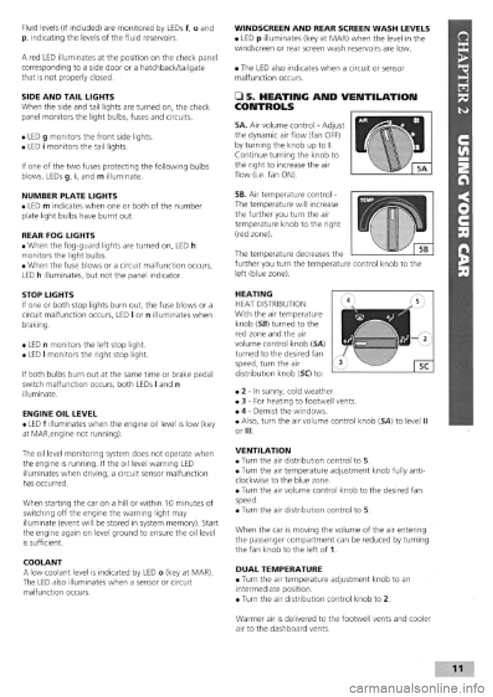
5A. Air volume control
-
Adjust
the dynamic air flow (fan OFF)
by turning the knob up to I.
Continue turning the knob to
the right to increase the air
flow (i.e. fan ON).
5B. Air temperature control -
The temperature will increase
the further you turn the air
temperature knob to the right
(red zone).
HEATING
HEAT DISTRIBUTION
With the air temperature
knob (56) turned to the
red zone and the air
volume control knob (5A)
turned to the desired fan
speed, turn the air
distribution knob (5C) to:
• 2
-
In sunny, cold weather.
• 3
-
For heating to footwell vents.
• 4
-
Demist the windows.
• Also, turn the air volume control knob (5A) to level II
or III.
VENTILATION
• Turn the air distribution control to 5.
• Turn the air temperature adjustment knob fully anti-
clockwise to the blue zone.
• Turn the air volume control knob to the desired fan
speed.
• Turn the air distribution control to 5.
When the car is moving the volume of the air entering
the passenger compartment can be reduced by turning
the fan knob to the left of 1.
DUAL TEMPERATURE
• Turn the air temperature adjustment knob to an
intermediate position.
• Turn the air distribution control knob to 2.
The temperature decreases the
further you turn the temperature control knob to the
left (blue zone).
Warmer air is delivered to the footwell vents and cooler
air to the dashboard vents.
Page 29 of 171
Thanks
are due to the excellent, knowledgeable and helpful staff at FIAT main dealers, Ryauto of Amblecote, in the West
Midlands for supplying vehicles and for their assistance with this chapter. In particular, thanks are due to the efficient Maurice
Hough, Service Manager, the experienced Foreman, Tony Morris, and young demon mechanic, Matthew Worsfold.
Some of the suggested inspection/replacement intervals may not correspond to those shown in the original handbook. The suggested
schedule, based on FIAT'S recommendations, takes into account the age of the vehicle and the annual MoT test in the UK.
In practice, because of the split between (mainly) 12 month/9,000 mile and 18 month/13,500 mile intervals, you will need to
service your Tipo or Tempra at most, if not every, 6 month interval.
IMPORTANT NOTE: Each service should be carried out at EITHER the recommended mileage OR the recommended time
interval, whichever comes first.
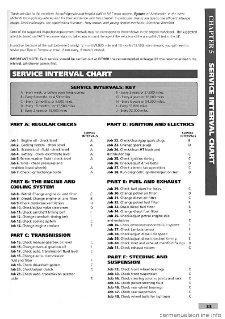
SERVICE INTERVAL CHART
SERVICE INTERVALS: KEY
A
-
Every week, or before every long journey. F
-
Every 3 years or 27,000 miles.
B
-
Every 6 months, or 4,500 miles. G
-
Every 4 years or 36,000 miles.
C - Every 12 months, or 9,000 miles. H
-
Every 6 years or 54,000 miles.
I
-
Every 63,000 miles. D - Every 18 months , or 13,500 miles.
H
-
Every 6 years or 54,000 miles.
I
-
Every 63,000 miles.
E
-
Every 2 years or 18,000 miles J
-
Every 72,000 miles.
PART A: REGULAR CHECKS
SERVICE INTERVALS
Job 1. Engine oil
-
check level A
Job 2. Cooling system
-
check level A
Job 3. Brake/clutch fluid
-
check level A
Job 4. Battery
-
check electrolyte level A
Job 5. Screen washer fluid
-
check level A
Job 6. Tyres
-
check pressures and
condition (road wheels) A
Job 7. Check lights/change bulbs A
PART B: THE ENGINE AND
COOLING SYSTEM
Job 8
-
Petrol. Change engine oil and filter C
Job 8
-
Diesel. Change engine oil and filter B
Job 9. Check crankcase ventilation H
Job 10. Check/adjust valve clearances D
Job 11. Check camshaft timing belt F
Job 12. Change camshaft timing belt I
Job 13. Check cooling system C
Job 14. Change engine coolant E
PART C: TRANSMISSION
Job 15. Check manual gearbox oil level C
Job 16. Change manual gearbox oil J
Job 17. Check auto, transmission fluid level C
Job 18. Change auto, transmission
fluid and filter F
Job 19. Check driveshaft gaiters C
Job 20. Check/adjust clutch C
Job 21. Check auto, transmission selector
cable E
PART D: IGNITION AND ELECTRICS
SERVICE INTERVALS
Job 22. Check/clean/gap spark plugs B
Job 23. Change spark plugs D
Job 24. Check/clean HT leads and
distributor cap C
Job 25. Check ignition timing C
Job 26. Check/adjust drive belt/s D
Job 27. Check electric fan operation C
Job 28. Run diagnostic ignition/injection test D
PART E: FUEL AND EXHAUST
Job 29. Check fuel pipes for leaks C
Job 30. Change petrol air filter D
Job 31. Change diesel air filter C
Job 32. Change petrol fuel filter F
Job 33. Drain diesel fuel filter B
Job 34. Change diesel fuel filter C
Job 35. Check/adjust petrol engine idle
and emissions C
Job 36. Check emission/evaporative/EGR systems F
Job 37. Check Lambda sensor F
Job 38. Check/adjust diesel idle speed C
Job 39. Check/adjust diesel injection timing E
Job 40. Check inlet and exhaust manifold fixings D
Job 41. Check exhaust system C
PART F: STEERING AND
SUSPENSION
Job 42. Check front wheel bearings C
Job 43. Check front suspension C
Job 44. Check steering column, joints and rack C
Job 45. Check power steering fluid C
Job 46. Check rear wheel bearings C
Job 47. Check rear suspension C
Job 48. Check wheel bolts for tightness C
Page 37 of 171
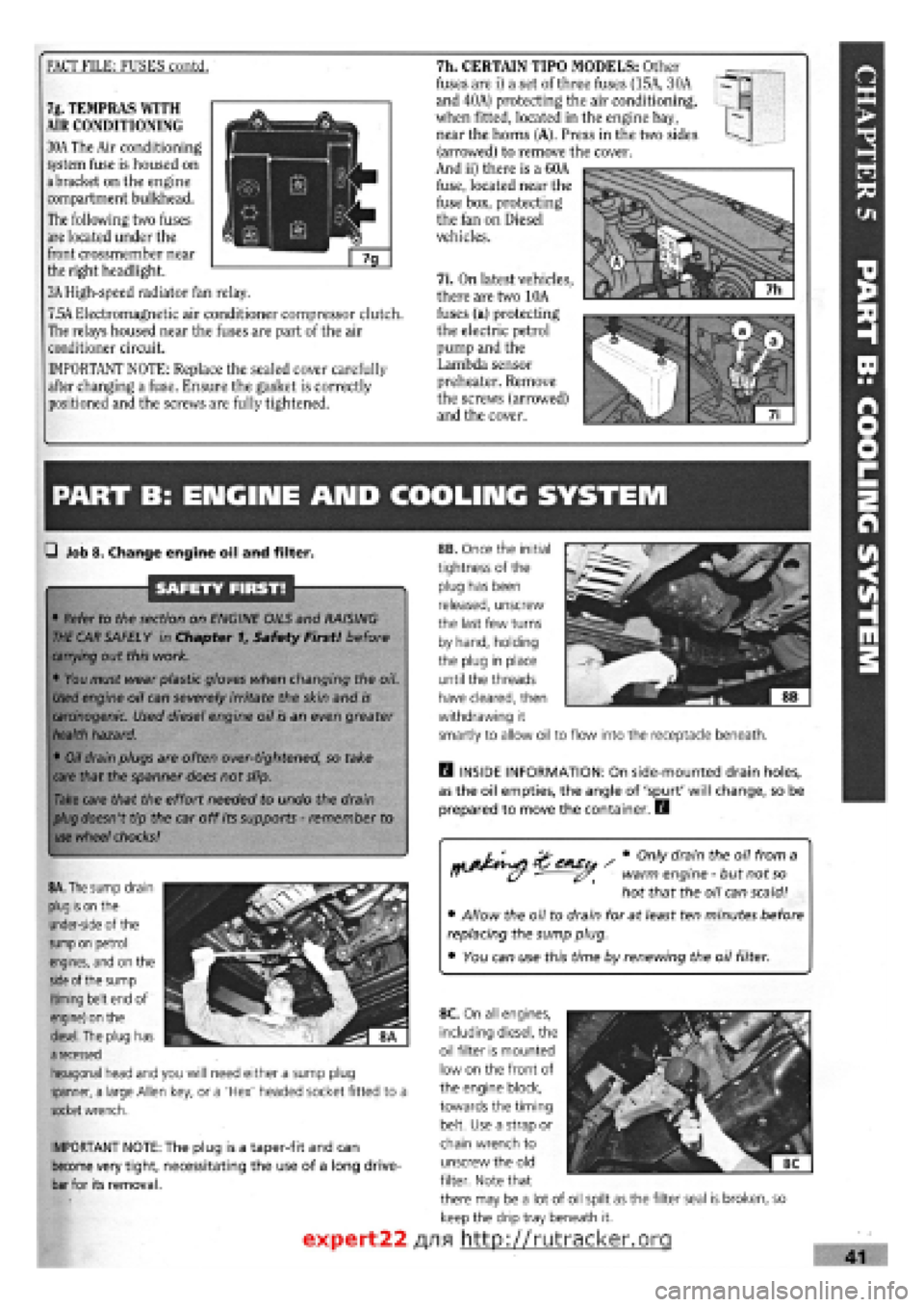
FACT FILE: FUSES contd. 7h. CERTAIN TIPO MODELS: Other
fuses are i) a set of three fuses (15A, 30A
and 40A) protecting the air conditioning,
when fitted, located in the engine bay,
near the horns (A). Press in the two sides
(arrowed) to remove the cover.
And ii) there is a 60A
fuse, located near the
fuse box, protecting
the fan on Diesel
vehicles.
7i. On latest vehicles,
there are two 10A
fuses (a) protecting
the electric petrol
pump and the
Lambda sensor
preheater. Remove
the screws (arrowed)
and the cover.
7g. TEMPRAS WITH
AIR CONDITIONING
30A The Air conditioning
system fuse is housed on
a bracket on the engine
compartment bulkhead.
The following two fuses
are located under the
front crossmember near
the right headlight.
3A High-speed radiator fan relay.
7.5A Electromagnetic air conditioner compressor clutch.
The relays housed near the fuses are part of the air
conditioner circuit.
IMPORTANT NOTE: Replace the sealed cover carefully
after changing a fuse. Ensure the gasket is correctly
positioned and the screws are fully tightened.
PART B: ENGIIME AND COOLING SYSTEM
Q Job 8. Change engine oil and filter.
SAFETY FIRST!
• Refer to the section on ENGINE OILS and RAISING
THE
CAR SAFELY in Chapter f, Safety First! before
carrying
out this work.
• You must wear plastic gloves when changing the oil.
Used
engine oil can severely irritate the skin and
is
carcinogenic.
Used diesel engine oil is an even greater
health
hazard.
•
Oil
drain plugs are often over-tightened, so take
care
that the spanner does not slip.
Take
care that the effort needed to undo the drain
plug
doesn't tip the car off its supports
-
remember to
use
wheel
chocks!
rtj&^si ' # °nly dram theu 0,7 fr°m a ff (y warm engine
-
but not
so
hot that the oil can scald!
• Allow the oil to drain for at least ten minutes before
replacing the sump plug.
• You can use this time by renewing the oil filter.
IMPORTANT NOTE: The plug is a taper-fit and can
become very tight, necessitating the use of a long drive-
bar for its removal.
H INSIDE INFORMATION: On side-mounted drain holes,
as the oil empties, the angle of 'spurt' will change, so be
prepared to move the container. E3
8A. The
sump drain
plug is on
the
under-side of the
sump on
petrol
engines, and on the
side
of the sump
(timing belt end of
engine) on the
diesel.
The plug has
a
recessed
hexagonal head and you will need either a sump plug
spanner, a large Allen key, or a 'Hex' headed socket fitted to a
socket
wrench.
8B. Once the initial
tightness of the
plug has been
released, unscrew
the last few turns
by hand, holding
the plug in place
until the threads
have cleared, then
withdrawing it
smartly to allow oil to flow into the receptacle beneath.
expert22
8C. On all engines,
including diesel, the
oil filter is mounted
low on the front of
the engine block,
towards the timing
belt. Use a strap or
chain wrench to
unscrew the old
filter. Note that
there may be a lot of oil spilt as the filter seal is broken, so
keep the drip tray beneath it.
/yifl http://rutracker.org
Page 44 of 171
• Job 25. Check ignition timing.
_ FACT FILE: IGNITION SYSTEM TYPES
Two different types of electronic ignition
systems have been fitted to the petrol
engines covered by this manual.
The earlier Breakerless Inductive Discharge System can
be adjusted. Its distributor is fitted as shown in illus-
tration 25A.
The later, Digiplex 2 system, has an integrated ignition
and fuel injection control system and any checks and
adjustments will need to be carried out by your FIAT
dealership with the appropriate diagnostic equipment.
See Job 28.
MAGNETI MARELLI BREAKERLESS INDUCTIVE
DISCHARGE IGNITION SYSTEM
CHECK VACUUM AND MECHANICAL ADVANCE SYSTEMS
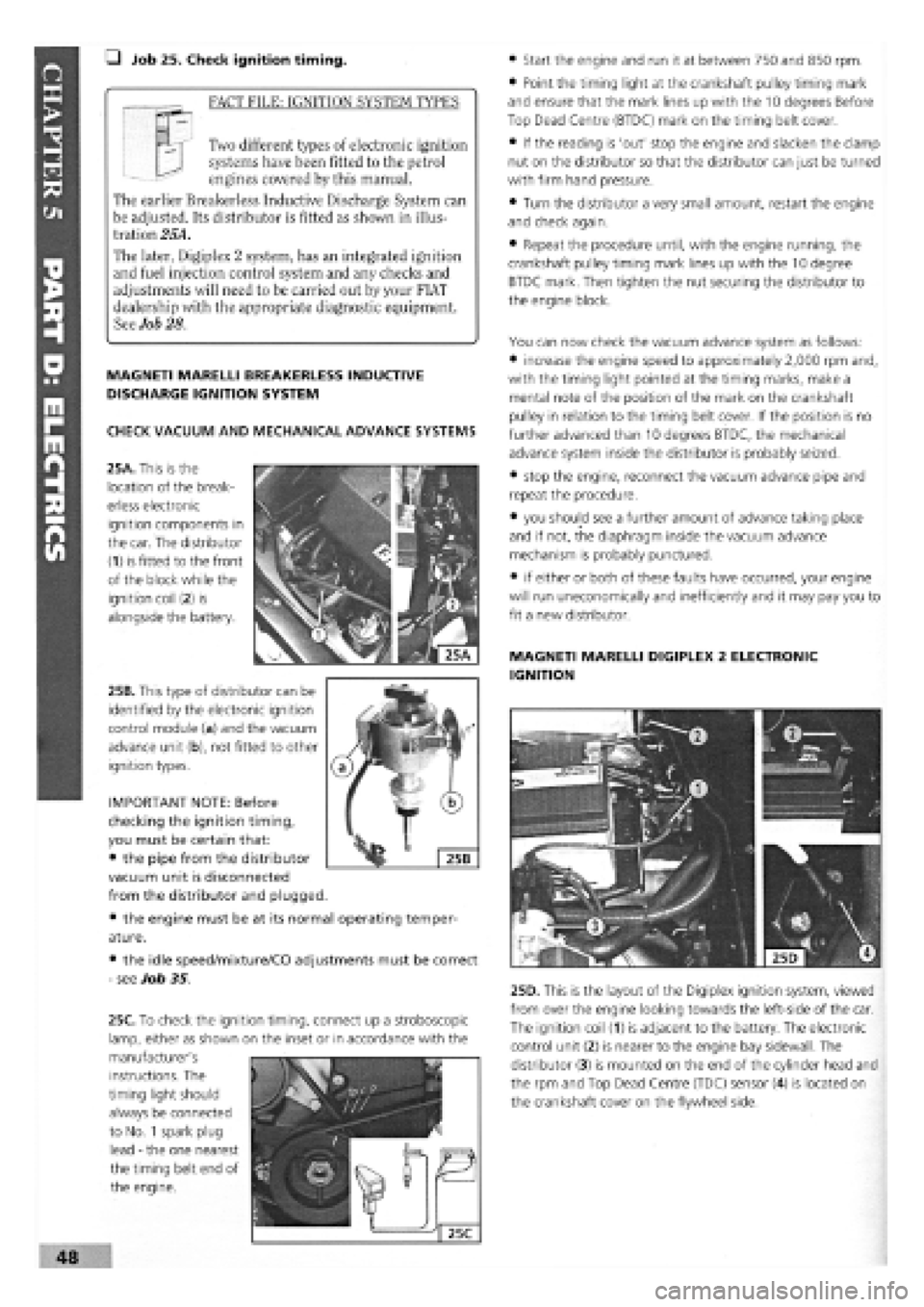
25A. This is the
location of the break-
erless electronic
ignition components in
the car. The distributor
(1) is fitted to the front
of the block while the
ignition coil
(2)
is
alongside the battery.
25B. This type of distributor can be
identified by the electronic ignition
control module (a) and the vacuum
advance unit (b), not fitted to other
ignition types.
• the engine must be at
ature.
• the idle speed/mixture/CO adjustments must be correct
-
see Job 35.
• Start the engine and run it at between 750 and 850 rpm.
• Point the timing light at the crankshaft pulley timing mark
and ensure that the mark lines up with the 10 degrees Before
Top Dead Centre (BTDC) mark on the timing belt cover.
• If the reading is 'out' stop the engine and slacken the clamp
nut on the distributor so that the distributor can just be turned
with firm hand pressure.
• Turn the distributor a very small amount, restart the engine
and check again.
• Repeat the procedure until, with the engine running, the
crankshaft pulley timing mark lines up with the 10 degree
BTDC mark. Then tighten the nut securing the distributor to
the engine block.
You can now check the vacuum advance system as follows:
• increase the engine speed to approximately 2,000 rpm and,
with the timing light pointed at the timing marks, make a
mental note of the position of the mark on the crankshaft
pulley in relation to the timing belt cover. If the position is no
further advanced than 10 degrees BTDC, the mechanical
advance system inside the distributor is probably seized.
• stop the engine, reconnect the vacuum advance pipe and
repeat the procedure.
• you should see a further amount of advance taking place
and if not, the diaphragm inside the vacuum advance
mechanism is probably punctured.
• if either or both of these faults have occurred, your engine
will run uneconomical^ and inefficiently and it may pay you to
fit a new distributor.
MAGNETI MARELLI DIGIPLEX 2 ELECTRONIC
IGNITION
25D. This is the layout of the Digiplex ignition system, viewed
from over the engine looking towards the left-side of the car.
The ignition coil (1) is adjacent to the battery. The electronic
control unit (2) is nearer to the engine bay sidewall. The
distributor (3) is mounted on the end of the cylinder head and
the rpm and Top Dead Centre (TDC) sensor (4) is located on
the crankshaft cover on the flywheel side.
IMPORTANT NOTE: Before
checking the ignition timing,
you must be certain that:
• the pipe from the distributor
vacuum unit is disconnected
from the distributor and plugged.
its normal operating temper-
instructions. The
timing light should
always be connected
to No.
1
spark plug
lead
-
the one nearest
the timing belt end of
the engine.
48
25C. To check the ignition timing, connect up a stroboscopic
lamp, either as shown on the inset or in accordance with the
manufacturer's
Page 45 of 171
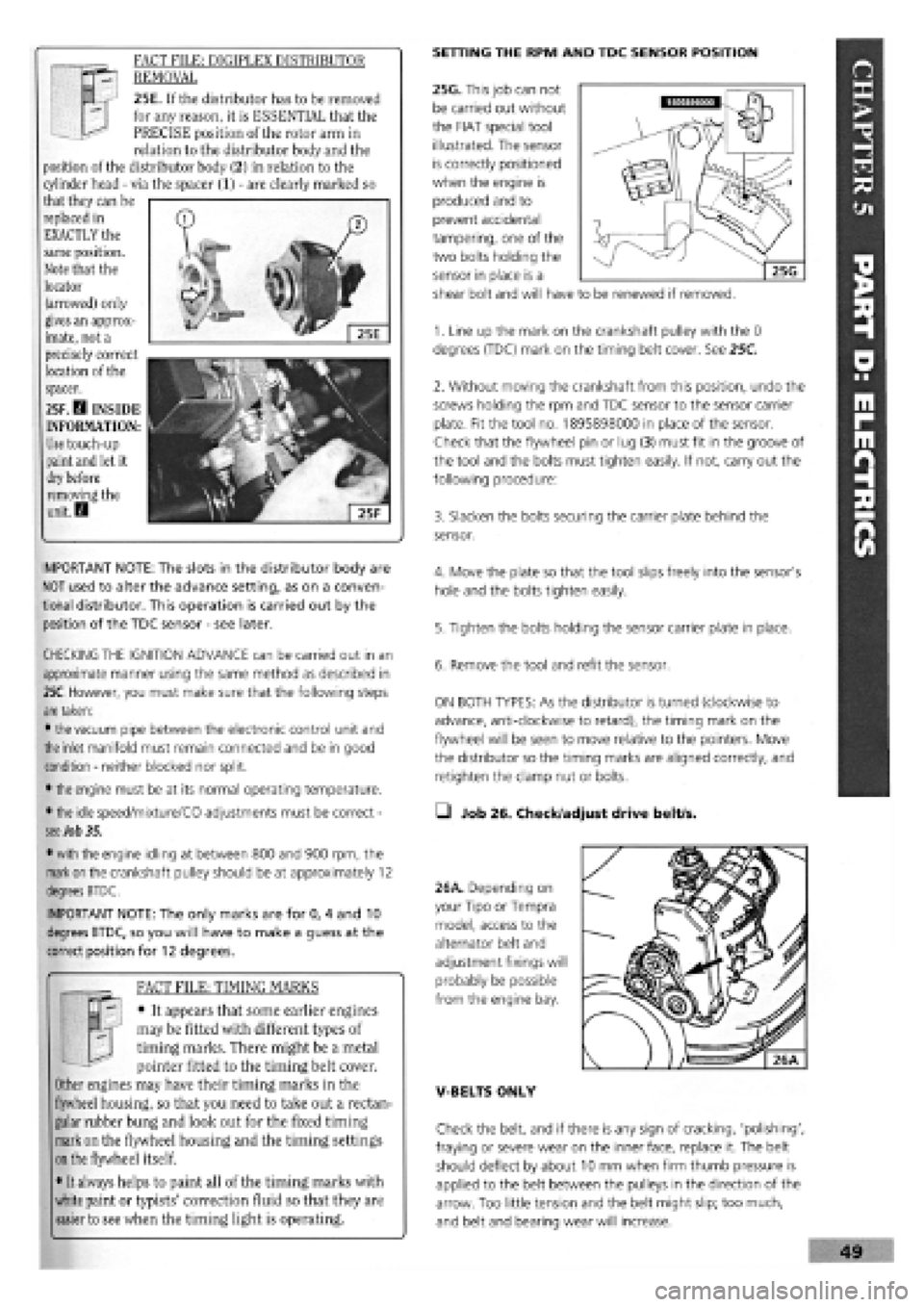
FACT FILE: DIGIPLEX DISTRIBUTOR
REMOVAL
25E. If the distributor has to be removed
for any reason, it is ESSENTIAL that the
PRECISE position of the rotor arm in
relation to the distributor body and the
position of the distributor body (2) in relation to the
cylinder head
-
via the spacer (1)
-
are clearly marked so
that they can be
replaced in
EXACTLY the
same position.
Note that the
locator
(arrowed) only
gives an approx-
imate, not a
precisely correct
location of the
spacer.
25F. D INSIDE
INFORMATION:
Use
touch-up
paint
and
let it
dry before
removing the
unit. D
SETTING THE RPM AND TDC SENSOR POSITION
25G. This job can not
be carried out without
the FIAT special tool
illustrated. The sensor
is correctly positioned
when the engine is
produced and to
prevent accidental
tampering, one of the
two bolts holding the
sensor in place is a
shear bolt and will have to be renewed if removed.
IMPORTANT NOTE: The slots in the distributor body are
NOT used to alter the advance setting, as on a conven-
tional distributor. This operation is carried out by the
position of the TDC sensor
-
see later.
CHECKING THE IGNITION ADVANCE can be carried out in an
approximate manner using the same method as described in
25C.
However, you must make sure that the following steps
are
taken:
•
the
vacuum pipe between the electronic control unit and
the
inlet manifold must remain connected and be in good
condition
-
neither blocked nor split.
•
the
engine must be at its normal operating temperature.
•
the
idle speed/mixture/CO adjustments must be correct
-
see Job 35.
•
with
the engine idling at between 800 and 900 rpm, the
mark on
the crankshaft pulley should be at approximately 12
degrees BTDC.
IMPORTANT NOTE: The only marks are for 0, 4 and 10
degrees BTDC, so you will have to make a guess at the
correct position for 12 degrees.
FACT FILE: TIMING MARKS
y-; • It appears that some earlier engines
H. j may be fitted with different types of
J timing marks. There might be a metal
pointer fitted to the timing belt cover.
Other engines may have their timing marks in the
flywheel housing, so that you need to take out a rectan-
gular rubber bung and look out for the fixed timing
mark on the flywheel housing and the timing settings
on
the flywheel itself.
• It always helps to paint all of the timing marks with
white paint or typists' correction fluid so that they are
easier to see when the timing light is operating.
1. Line up the mark on the crankshaft pulley with the 0
degrees (TDC) mark on the timing belt cover. See 25C.
2. Without moving the crankshaft from this position, undo the
screws holding the rpm and TDC sensor to the sensor carrier
plate. Fit the tool no. 1895898000 in place of the sensor.
Check that the flywheel pin or lug (3) must fit in the groove of
the tool and the bolts must tighten easily. If not, carry out the
following procedure:
3. Slacken the bolts securing the carrier plate behind the
sensor.
4. Move the plate so that the tool slips freely into the sensor's
hole and the bolts tighten easily.
5. Tighten the bolts holding the sensor carrier plate in place.
6. Remove the tool and refit the sensor.
ON BOTH TYPES: As the distributor is turned (clockwise to
advance, anti-clockwise to retard), the timing mark on the
flywheel will be seen to move relative to the pointers. Move
the distributor so the timing marks are aligned correctly, and
retighten the clamp nut or bolts.
• Job 26. Check/adjust drive belt/s.
26A. Depending on
your Tipo or Tempra
model, access to the
alternator belt and
adjustment fixings will
probably be possible
from the engine bay.
V-BELTS ONLY
Check the belt, and if there is any sign of cracking, 'polishing',
fraying or severe wear on the inner face, replace it. The belt
should deflect by about 10 mm when firm thumb pressure is
applied to the belt between the pulleys in the direction of the
arrow. Too little tension and the belt might slip; too much,
and belt and bearing wear will increase.
Page 46 of 171
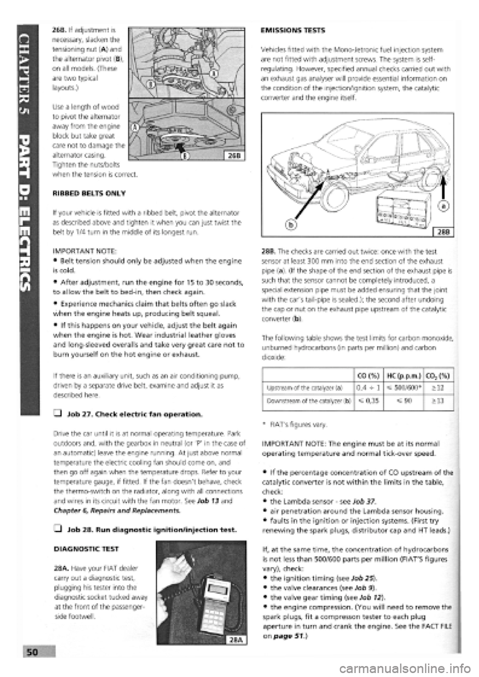
26B. If adjustment is
necessary, slacken the
tensioning nut (A) and
the alternator pivot (B),
on all models. (These
are two typical
layouts.)
Use a length of wood
to pivot the alternator
away from the engine
block but take great
care not to damage the
alternator casing.
Tighten the nuts/bolts
when the tension is correct.
RIBBED BELTS ONLY
If your vehicle is fitted with a ribbed belt, pivot the alternator
as described above and tighten it when you can just twist the
belt by 1/4 turn in the middle of its longest run.
IMPORTANT NOTE:
• Belt tension should only be adjusted when the engine
is cold.
• After adjustment, run the engine for 15 to 30 seconds,
to allow the belt to bed-in, then check again.
• Experience mechanics claim that belts often go slack
when the engine heats up, producing belt squeal.
• If this happens on your vehicle, adjust the belt again
when the engine is hot. Wear industrial leather gloves
and long-sleeved overalls and take very great care not to
burn yourself on the hot engine or exhaust.
If there is an auxiliary unit, such as an air conditioning pump,
driven by a separate drive belt, examine and adjust it as
described here.
Q Job 27. Check electric fan operation.
Drive the car until it is at normal operating temperature. Park
outdoors and, with the gearbox in neutral (or 'P' in the case of
an automatic) leave the engine running. At just above normal
temperature the electric cooling fan should come on, and
then go off again when the temperature drops. Refer to your
temperature gauge, if fitted. If the fan doesn't behave, check
the thermo-switch on the radiator, along with all connections
and wires in its circuit with the fan motor. See Job 13 and
Chapter
6,
Repairs and Replacements.
• Job 28. Run diagnostic ignition/injection test.
DIAGNOSTIC TEST
28A. Have your FIAT dealer
carry out a diagnostic test,
plugging his tester into the
diagnostic socket tucked away
at the front of the passenger-
side footwell.
EMISSIONS TESTS
Vehicles fitted with the Mono-Jetronic fuel injection system
are not fitted with adjustment screws. The system is self-
regulating. However, specified annual checks carried out with
an exhaust gas analyser will provide essential information on
the condition of the injection/ignition system, the catalytic
converter and the engine itself.
28B. The checks are carried out twice: once with the test
sensor at least 300 mm into the end section of the exhaust
pipe (a). (If the shape of the end section of the exhaust pipe is
such that the sensor cannot be completely introduced, a
special extension pipe must be added ensuring that the joint
with the car's tail-pipe is sealed.); the second after undoing
the cap or nut on the exhaust pipe upstream of the catalytic
converter (b).
The following table shows the test limits for carbon monoxide,
unburned hydrocarbons (in parts per million) and carbon
dioxide:
CO (%) HC (p.p.m.) C02(%)
Upstream of the catalyzer (a) 0,4 -h 1 500/600* >12
Downstream of the catalyzer (b)
=£
0,35 =s 90 >13
* FIAT's figures vary.
IMPORTANT NOTE: The engine must be at its normal
operating temperature and normal tick-over speed.
• if the percentage concentration of CO upstream of the
catalytic converter is not within the limits in the table,
check:
• the Lambda sensor
-
see Job 37.
• air penetration around the Lambda sensor housing.
• faults in the ignition or injection systems. (First try
renewing the spark plugs, distributor cap and HT leads.)
If, at the same time, the concentration of hydrocarbons
is not less than 500/600 parts per million (FIAT'S figures
vary), check:
• the ignition timing (see Job 25).
• the valve clearances (see Job 9).
• the valve gear timing (see Job 12).
• the engine compression. (You will need to remove the
spark plugs, fit a compresson tester to each plug
aperture in turn and crank the engine. See the FACT FILE
on page 51.)
Page 48 of 171
• Job 32. Change petrol fuel filter. IMPORTANT NOTES:
• Wear plastic gloves and goggles and have a large rag
and a suitable fire extinguisher ready.
• Place a container beneath the filter to catch fuel
spillage.
• After fitting the new filter in place, refit the casing,
ensure no traces of fuel are left, reconnect the battery and
restart the engine.
• Check carefully to ensure there are no leaks before
refitting the cover.
• Job 33. Drain diesel fuel filter.
IMPORTANT NOTE: Some models are fitted with a water-
in-fuel sensor. Drain the filter when the warning light
comes on. Unplug the sensor from the base of the filter,
first.
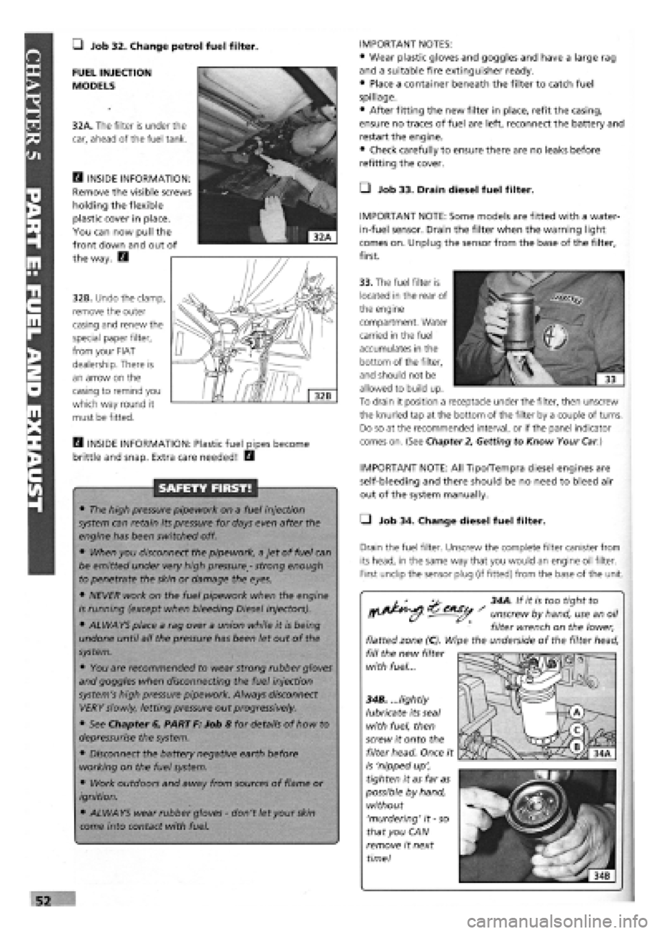
FUEL INJECTION
MODELS
32A. The filter is under the
car, ahead of the fuel tank.
E3 INSIDE INFORMATION:
Remove the visible screws
holding the flexible
plastic cover in place.
You can now pull the
front down and out of
the way. E3
32B. Undo the clamp,
remove the outer
casing and renew the
special paper filter,
from your FIAT
dealership. There is
an arrow on the
casing to remind you
which way round it
must be fitted.
33. The fuel filter is
located in the rear of
the engine
compartment. Water
carried in the fuel
accumulates in the
bottom of the filter,
and should not be
allowed to build up.
To drain it position a receptacle under the filter, then unscrew
the knurled tap at the bottom of the filter by a couple of turns.
Do so at the recommended interval, or if the panel indicator
comes on. (See Chapter
2,
Getting to Know Your
Car.)
H INSIDE INFORMATION: Plastic fuel pipes become
brittle and snap. Extra care needed! E3
SAFETY FIRST!
• The high pressure pipework on a fuel injection
system can retain its pressure for days even after the
engine has been switched off.
• When you disconnect the pipework, a jet of fuel can
be emitted under very high pressure
-
strong enough
to penetrate the skin or damage the eyes.
• NEVER work on the fuel pipework when the engine
is running (except when bleeding Diesel injectors).
• ALWAYS place a rag over a union while it is being
undone until all the pressure has been let out of the
system.
• You are recommended to wear strong rubber gloves
and goggles when disconnecting the fuel injection
system's high pressure pipework. Always disconnect
VERY slowly, letting pressure out progressively.
• See Chapter 6, PART F: Job 8 for details of how to
depressurise the system.
• Disconnect the battery negative earth before
working on the fuel system.
• Work outdoors and away from sources of flame or
ignition.
• ALWAYS wear rubber gloves
-
don't let your
skin
come into contact with fuel.
IMPORTANT NOTE: All Tipo/Tempra diesel engines are
self-bleeding and there should be no need to bleed air
out of the system manually.
• Job 34. Change diesel fuel filter.
Drain the fuel filter. Unscrew the complete filter canister from
its head, in the same way that you would an engine oil filter.
First undip the sensor plug (if fitted) from the base of the unit.
^ 34A. If it is too tight to
^^ - unscrew by hand, use an oil
filter wrench on the lower,
flatted zone (C). Wipe the underside of the filter head,
fill the new filter
with fuel...
34B. ...lightly
lubricate its seal
with fuel, then
screw it onto the
filter head. Once it
is 'nipped up',
tighten it as far as
possible by hand,
without
'murdering' it
-
so
that you CAN
remove it next
time!
Page 50 of 171
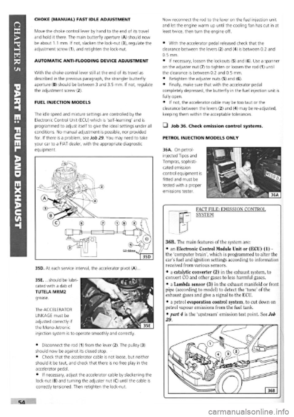
CHOKE (MANUAL) FAST IDLE ADJUSTMENT
Move the choke control lever by hand to the end of its travel
and hold it there. The main butterfly aperture (A) should now
be about 1.1 mm. If not, slacken the lock-nut (3), regulate the
adjustment screw (1), and retighten the lock-nut.
AUTOMATIC ANTI-FLOODING DEVICE ADJUSTMENT
With the choke control lever still at the end of its travel as
described in the previous paragraph, the strangler butterfly
aperture (B) should be between 3 and 3.5 mm. If not, regulate
the adjustment screw (2).
FUEL INJECTION MODELS
The idle speed and mixture settings are controlled by the
Electronic Control Unit (ECU) which is 'self-learning' and is
programmed to adjust itself to give the ideal settings under all
conditions. No manual adjustment is possible, nor provided
for. If there is a problem, see Job 29 You may need to take
your car to a FIAT dealer, with the appropriate diagnostic
equipment.
35D. At each service interval, the accelerator pivot (A).
35E. ...should be lubri-
cated with a dab of
TUTELA MRM2
grease.
The ACCELERATOR
LINKAGE must be
adjusted correctly if
the Mono-Jetronic
injection system is to operate smoothly and correctly.
• Disconnect the rod (1) from the lever (2). The pulley (3)
should now be against its closed stop.
• Check that the accelerator cable is not loose, but neither
should it be taut, and check that there is no free play in the
accelerator pedal.
• If necessary, adjust the accelerator cable by slackening the
lock-nut (B) and turning the adjuster nut (C) until the cable is
correctly tensioned. Then retighten the lock-nut.
Now reconnect the rod to the lever on the fuel injection unit
and let the engine warm up until the cooling fan has cut in at
least twice, then turn the engine off.
• With the accelerator pedal released check that the
clearance between the levers (2) and (4) is between 0.2 and
0.5 mm.
• If necessary, loosen the lockouts (5) and (6). Use a spanner
on the adjuster nut (7) to tighten or loosen the rod (1) until
the clearance is between 0.2 and 0.5 mm.
• Retighten the adjuster nuts (5) and (6).
• Finally, make sure that with the accelerator pedal
completely depressed, the butterfly in the fuel injection unit is
fully open.
• If not, the accelerator cable may be too taut or the
clearance between the levers (2) and (4) may be re-adjusted,
keeping them within the acceptable tolerances.
Q Job 36. Check emission control systems.
PETROL INJECTION MODELS ONLY
36A. On petrol-
injected Tipos and
Tempras, sophisti-
cated emission
control equipment is
fitted and must be
tested with a proper
emissions tester.
FACT FILE: EMISSION CONTROL
SYSTEM
36B. The main features of the system are:
• an Electronic Control Module Unit or (ECU) (1) -
the 'computer brain', which is programmed to alter the
car's fuel and ignition settings according to information
received from various sensors.
• a catalytic converter (2) in the exhaust system, to
convert CO and other gases to less harmful gases.
• a Lambda sensor (3) in the exhaust manifold or front
pipe (according to model) to detect the 'tune' of the
exhaust gases and give a signal to the ECU.
• a petrol evaporation control system, to cut down on
petrol vapour emissions from the fuel tank.
• part 4 is the 'upstream' emission test point. See Job
29.
Page 51 of 171
ELECTRONIC CONTROL MODULE: The ECU is not an item
that requires any servicing. If you think it might be faulty, ask
your FIAT dealer or fuel injection specialist to check it for you.
This must be done by someone with the correct FIAT plug-in
diagnostic equipment and data.
CATALYTIC CONVERTER: The CAT is not serviceable. If it
fails, you will be told at the MoT test. Replacement is
expensive, so we recommend you obtain a second opinion
before replacing the 'cat'.
LAMBDA SENSOR: For information concerning the sensor,
see
Job
37.
I' sensor is a simple job (see
Chapter 6, Repairs and
Replacements, PART F: FUEL AND EXHAUST), but it
can only be tested by your FIAT dealer with the correct
equipment
• If the sensor is faulty, have it renewed by your
dealer.
• Lambda sensors are very delicate and easily
damaged. It is not likely that you would be able to
return one to the supplier if you fitted it yourself.
• Lambda sensors are only fitted to cars with a
catalytic converter.
• Job 38. Check/adjust diesel idle speed.
To accurately check and adjust the diesel's idle speed you
need a diesel-specific rev-counter. If you're happy with the idle
speed, leave well alone. But if you're convinced the idle is
incorrect, it's best to take the car to a FIAT dealer. If you wish
to adjust the speed yourself, get the engine to normal
operating temperature, and check there is some free play in
the accelerator cable before proceeding.
ADJUSTMENT
-
BOSCH PUMP
D INSIDE INFORMATION: If the canister is flooded with
petrol, it is probable that one of the purge valves or
purge valve floats is faulty. Get this investigated and
rectified by a FIAT dealer. If the engine cuts out and then
restarts after a while, it could be the breather hose
valve, fitted under the fuel filler neck. This one-way
valve allows air to enter the tank as the fuel level falls,
otherwise an air lock can prevent fuel reaching the
engine. To test the valve, take off the pipe clips, remove
the valve and test it as for the canister one-way valve,
above. It should allow air to pass into the tank, but not
the other way. H
Q Job 37. Check Lambda sensor.
PETROL INJECTION MODELS ONLY
For
a
description of how the sensor works, see Job 36, FACT
FILE: EMISSION CONTROL SYSTEM. It should be checked at
the recommended interval
-
the cost of checking and
replacing the sensor is far less than that of having to replace
the catalytic converter because it has been polluted due to a
sensor fault.
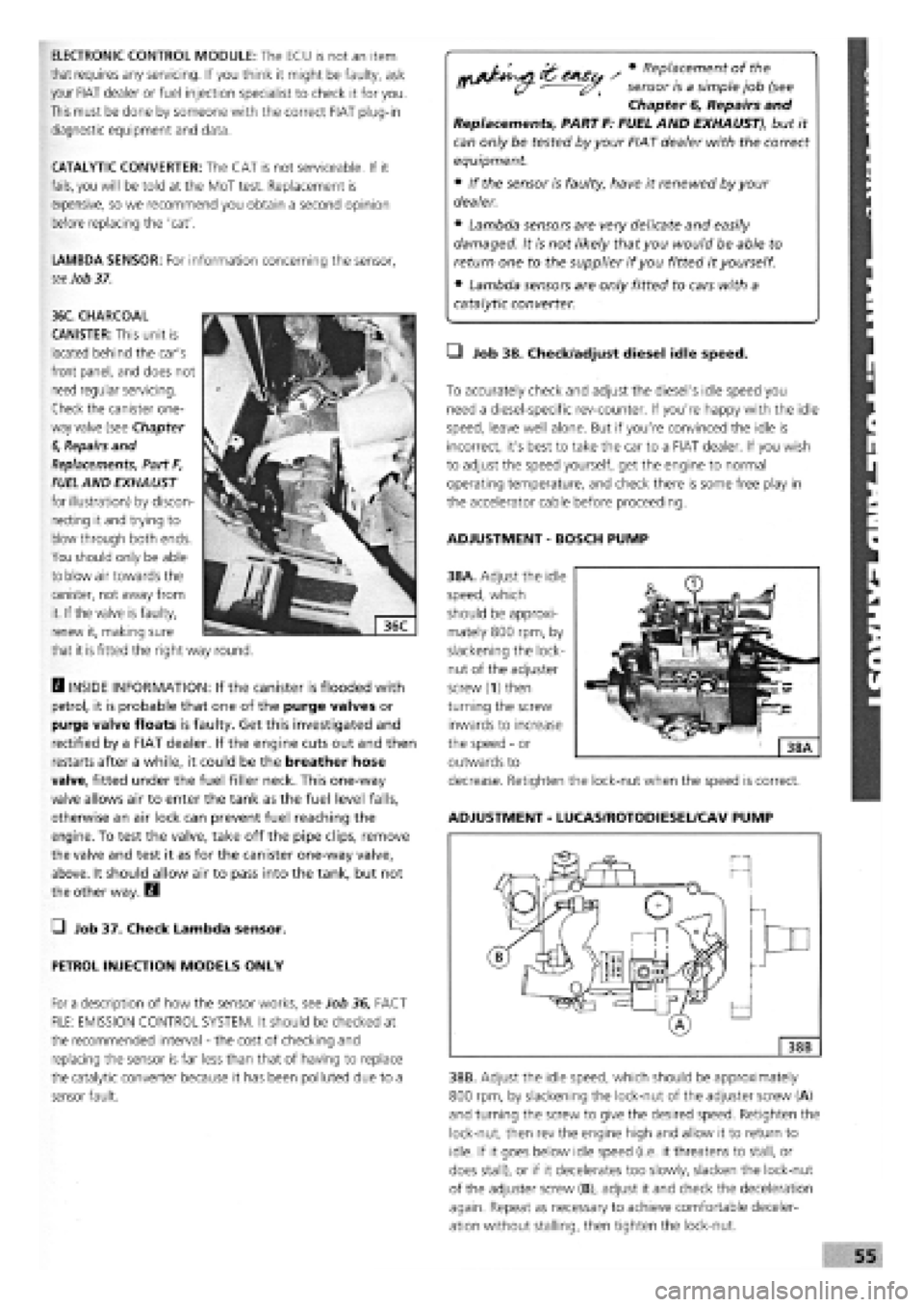
38A. Adjust the idle
speed, which
should be approxi-
mately 800 rpm, by
slackening the lock-
nut of the adjuster
screw (1) then
turning the screw
inwards to increase
the speed
-
or
outwards to
decrease. Retighten the lock-nut when the speed is correct.
ADJUSTMENT
-
LUCAS/ROTODIESEL/CAV PUMP
38B. Adjust the idle speed, which should be approximately
800 rpm, by slackening the lock-nut of the adjuster screw (A)
and turning the screw to give the desired speed. Retighten the
lock-nut, then rev the engine high and allow it to return to
idle. If it goes below idle speed (i.e. it threatens to stall, or
does stall), or if it decelerates too slowly, slacken the lock-nut
of the adjuster screw (B), adjust it and check the deceleration
again. Repeat as necessary to achieve comfortable deceler-
ation without stalling, then tighten the lock-nut.
36C. CHARCOAL
CANISTER: This unit is
located behind the car's
front panel, and does not
need regular servicing.
Check the canister one-
way valve (see Chapter
6,
Repairs and
Replacements, Part F,
FUEL
AND EXHAUST
for illustration) by discon-
necting it and trying to
blow through both ends.
You should only be able
to blow air towards the
canister, not away from
it. If the valve is faulty,
renew it, making sure
that it
is
fitted the right way round.
Page 56 of 171
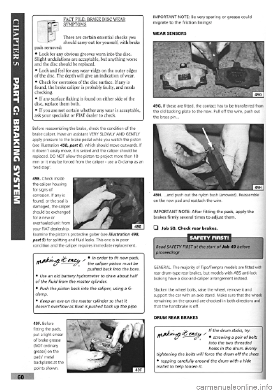
49H. ...and push out the nylon bush (arrowed). Reassemble
on the new pad and reattach the wire.
IMPORTANT NOTE: After fitting the pads, apply the
brakes firmly several times to adjust them.
• Job 50. Check rear brakes.
SAFETY FIRST!
Read SAFETY FIRST at the start of Job 49 before
proceeding!
GENERAL. The majority of Tipo/Tempra models are fitted with
rear drum-type rear brakes, but models with ABS anti-lock
braking have a disc-and-caliper arrangement instead.
Slacken the wheel bolts, raise the wheel, remove it and
support the car with an axle stand. Make sure that the wheels
remaining on the ground are chocked in both directions and
that the handbrake is off.
DRUM REAR BRAKES
If the drum
sticks,
try:
• screwing a pair of
bolts
into the two threaded
holes in the drum. Evenly
tightening the bolts will force the drum off the
shoes.
• tapping carefully around the drum with a hide
mallet to help loosen it.
s Vn order to fit new pads,
r> - the caliper piston must be
pushed back into the bore.
• Use an old battery hydrometer to draw about half
of the fluid from the master cylinder.
• Push the piston back into the caliper, using a G-
clamp.
• Keep an eye on the master cylinder so that it
doesn't overflow as fluid is pushed back up the pipe.
IMPORTANT NOTE: Be very sparing or grease could
migrate to the friction linings!
WEAR SENSORS I I There are certain essential checks you
should carry out for yourself, with brake
pads removed:
• Look for any obvious grooves worn into the disc.
Slight undulations are acceptable, but anything worse
and the disc should be replaced.
• Look and feel for any wear-ridge on the outer edges
of the disc. The depth will give an indication of wear.
• Check for corrosion of the disc surface. If any is
found, the brake caliper is probably faulty, and needs
checking.
• If any surface flaking is found on either side of the
disc, replace them both.
• If you are not certain whether any wear is acceptable,
ask your specialist or FIAT dealer to check.
FACT FILE: BRAKE DISC WEAR
SYMPTOMS
Before reassembling the brake, check the condition of the
brake caliper. Have an assistant VERY SLOWLY AND GENTLY
apply pressure to the brake pedal while you watch the piston
(see illustration 49B, part
8),
which should move outwards. If
it doesn't easily move, it is seized and the caliper should be
replaced. DO NOT allow the piston to project more than 10
mm or it may be forced from the caliper
-
use a G-clamp as an
'end stop'.
49F. Before
fitting the pads,
put a light smear
of brake grease
(NOT ordinary
grease) on the
pads' metal
backplates at the
points shown.
49G. If these are fitted, the contact has to be transferred from
the old backing plate to the new. Pull off the wire, push out
the brass pin...
49E. Check inside
the caliper housing
for signs of
corrosion. If any is
found, or the seal is
damaged, the caliper
should be exchanged
for a new or
overhauled unit from
your FIAT dealership.
Examine the piston's protective gaiter (see illustration 49B,
part 9) for splitting and fluid leaks. This one is in poor
condition and the caliper requires immediate replacement.