FORD C MAX 2011 2.G Owners Manual
Manufacturer: FORD, Model Year: 2011, Model line: C MAX, Model: FORD C MAX 2011 2.GPages: 296, PDF Size: 7.87 MB
Page 161 of 296
Downloaded from www.Manualslib.com manuals search engine Note:
The system will no longer control
your speed. The cruise control indicator will
not illuminate but the system will retain the
speed that you previously set.
Resuming the set speed
Pull the RES switch.
The cruise control indicator will illuminate
and the system will attempt to resume the
speed that you previously set.
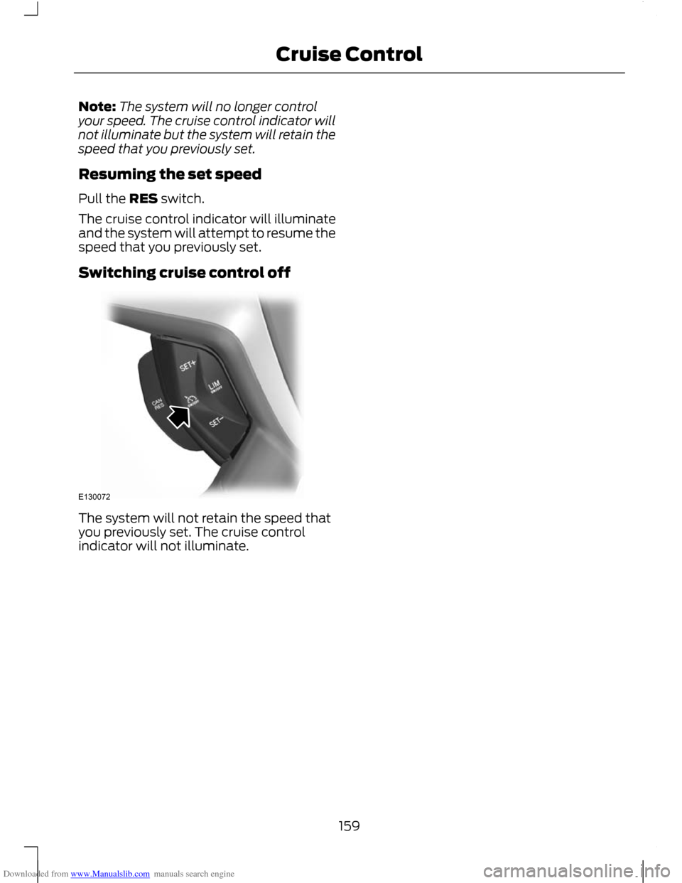
Switching cruise control off The system will not retain the speed that
you previously set. The cruise control
indicator will not illuminate.
159
Cruise ControlE130072
Page 162 of 296
Downloaded from www.Manualslib.com manuals search engine PRINCIPLE OF OPERATION
WARNING
When you are going downhill, your
speed may increase above the set
speed. The system will not apply the
brakes but a warning will be given. The system allows you to set a speed, to
which the vehicle then becomes limited.
The set speed will become the effective
maximum speed of the vehicle, but with
the option to temporarily exceed this limit
if required.
USING THE SPEED LIMITER
Note:
The set speed limit can be
intentionally exceeded for a short period if
required, for example when overtaking.
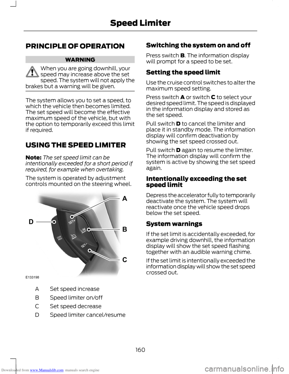
The system is operated by adjustment
controls mounted on the steering wheel. Set speed increase
A
Speed limiter on/off
B
Set speed decrease
C
Speed limiter cancel/resume
D Switching the system on and off
Press switch B. The information display
will prompt for a speed to be set.
Setting the speed limit
Use the cruise control switches to alter the
maximum speed setting.
Press switch A or switch C to select your
desired speed limit. The speed is displayed
in the information display and stored as
the set speed.
Pull switch D to cancel the limiter and
place it in standby mode. The information
display will confirm deactivation by
showing the set speed crossed out.
Pull switch D again to resume the limiter.
The information display will confirm the
system is active by showing the set speed
again.
Intentionally exceeding the set
speed limit
Depress the accelerator fully to temporarily
deactivate the system. The system will
reactivate once the vehicle speed drops
below the set speed.
System warnings
If the set limit is accidentally exceeded, for
example driving downhill, the information
display will show the set speed flashing
together with an audible warning chime.
If the set limit is intentionally exceeded the
information display will show the set speed
crossed out.
160
Speed LimiterE133198ABCD
Page 163 of 296
Downloaded from www.Manualslib.com manuals search engine GENERAL INFORMATION
WARNINGS
Use load securing straps to an
approved standard, e.g. DIN.
Make sure that you secure all loose
items properly.
Place luggage and other loads as low
and as far forward as possible within
the luggage or loadspace.
Do not drive with the tailgate or rear
door open. Exhaust fumes may enter
the vehicle.
Do not exceed the maximum front
and rear axle loads for your vehicle.
See Vehicle Identification Plate
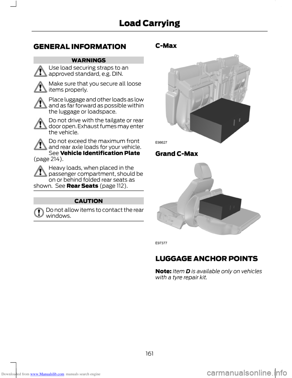
(page 214). Heavy loads, when placed in the
passenger compartment, should be
on or behind folded rear seats as
shown. See Rear Seats (page 112). CAUTION
Do not allow items to contact the rear
windows. C-Max
Grand C-Max
LUGGAGE ANCHOR POINTS
Note:
Item D is available only on vehicles
with a tyre repair kit.
161
Load CarryingE98627 E97377
Page 164 of 296
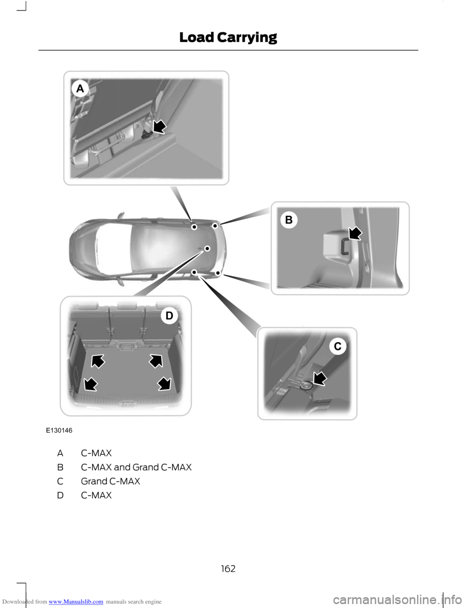
Downloaded from www.Manualslib.com manuals search engine C-MAX
A
C-MAX and Grand C-MAX
B
Grand C-MAX
C
C-MAX
D
162
Load CarryingE130146BACD
Page 165 of 296
Downloaded from www.Manualslib.com manuals search engine LUGGAGE COVERS
WARNING
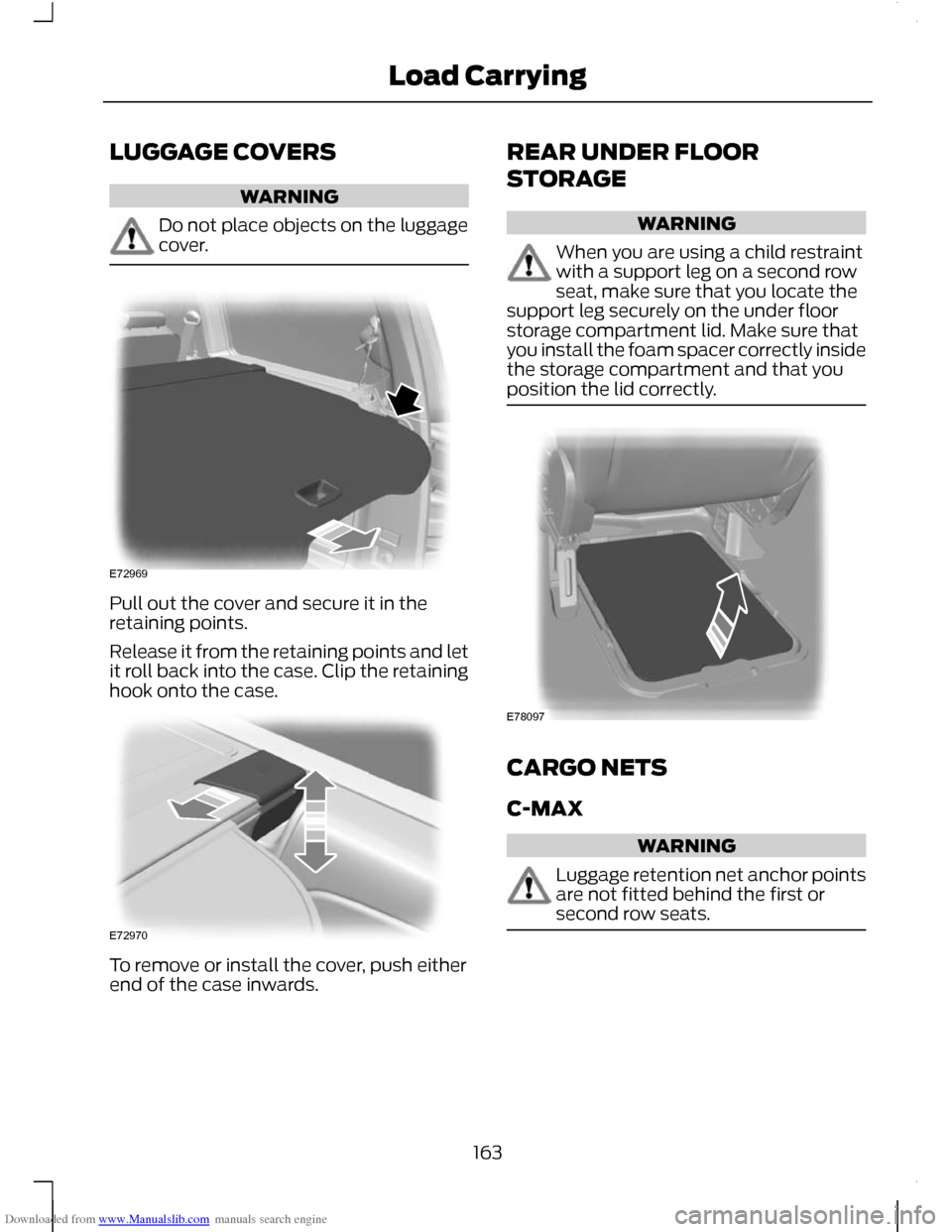
Do not place objects on the luggage
cover.
Pull out the cover and secure it in the
retaining points.
Release it from the retaining points and let
it roll back into the case. Clip the retaining
hook onto the case.
To remove or install the cover, push either
end of the case inwards. REAR UNDER FLOOR
STORAGE WARNING
When you are using a child restraint
with a support leg on a second row
seat, make sure that you locate the
support leg securely on the under floor
storage compartment lid. Make sure that
you install the foam spacer correctly inside
the storage compartment and that you
position the lid correctly. CARGO NETS
C-MAX
WARNING
Luggage retention net anchor points
are not fitted behind the first or
second row seats.
163
Load CarryingE72969 E72970 E78097
Page 166 of 296
Downloaded from www.Manualslib.com manuals search engine Grand C-MAX
WARNING
Luggage retention net anchor points
are not fitted behind the first row
seats, but are fitted behind the
second row seats. Luggage retention net
Installing the net
CAUTIONS
Do not move the rear seats when the
cargo net is installed.
Do not use the cargo net if the third
row seats are in use.
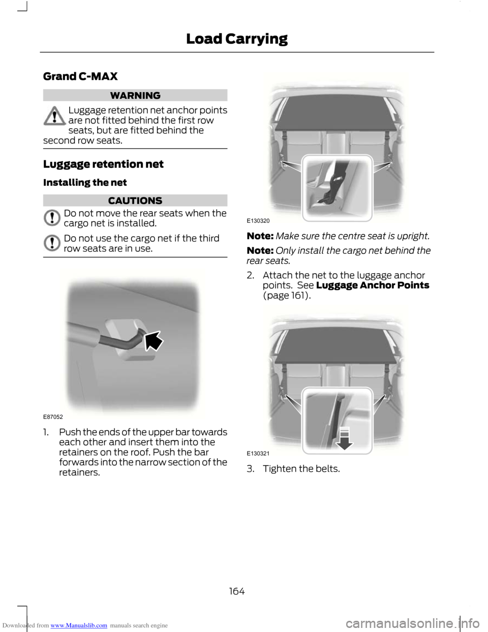
1.
Push the ends of the upper bar towards
each other and insert them into the
retainers on the roof. Push the bar
forwards into the narrow section of the
retainers. Note:
Make sure the centre seat is upright.
Note: Only install the cargo net behind the
rear seats.
2. Attach the net to the luggage anchor points. See Luggage Anchor Points
(page 161). 3. Tighten the belts.
164
Load CarryingE87052 E130320 E130321
Page 167 of 296
Downloaded from www.Manualslib.com manuals search engine Removing the net
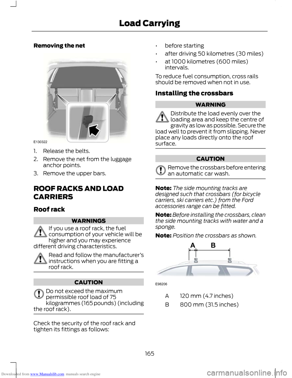
1. Release the belts.
2. Remove the net from the luggage
anchor points.
3. Remove the upper bars.
ROOF RACKS AND LOAD
CARRIERS
Roof rack WARNINGS
If you use a roof rack, the fuel
consumption of your vehicle will be
higher and you may experience
different driving characteristics. Read and follow the manufacturer
’s
instructions when you are fitting a
roof rack. CAUTION
Do not exceed the maximum
permissible roof load of 75
kilogrammes (165 pounds) (including
the roof rack). Check the security of the roof rack and
tighten its fittings as follows: •
before starting
• after driving 50 kilometres (30 miles)
• at 1000 kilometres (600 miles)
intervals.
To reduce fuel consumption, cross rails
should be removed when not in use.
Installing the crossbars WARNING
Distribute the load evenly over the
loading area and keep the centre of
gravity as low as possible. Secure the
load well to prevent it from slipping. Never
place any loads directly onto the roof
surface. CAUTION
Remove the crossbars before entering
an automatic car wash.
Note:
The side mounting tracks are
designed such that crossbars (for bicycle
carriers, ski carriers etc.) from the Ford
accessories range can be fitted.
Note: Before installing the crossbars, clean
the side mounting tracks with water and a
sponge.
Note: Position the crossbars as shown. 120 mm (4.7 inches)
A
800 mm (31.5 inches)
B
165
Load CarryingE130322 ABE98206
Page 168 of 296
Downloaded from www.Manualslib.com manuals search engine Note:
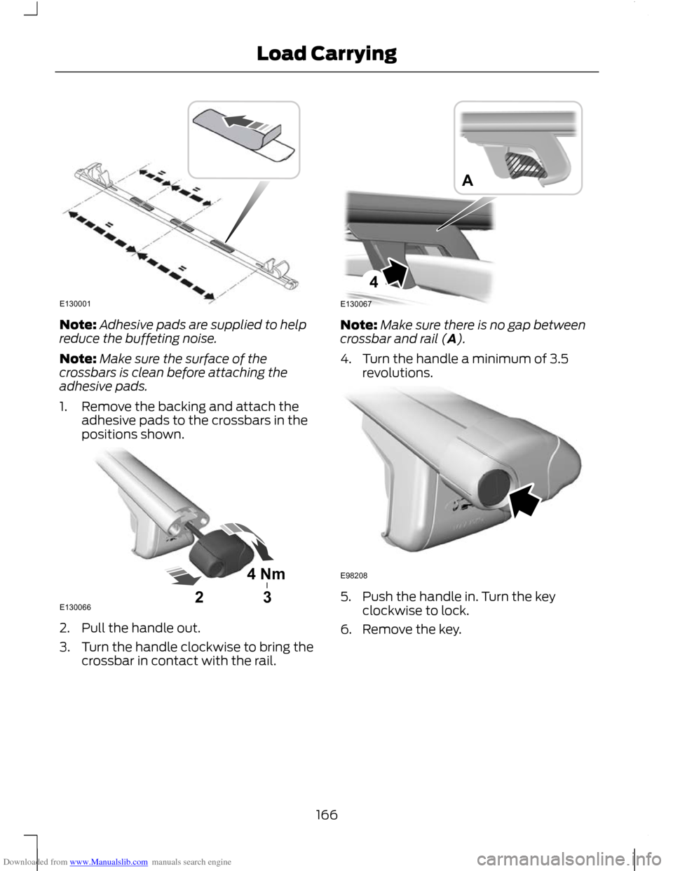
Adhesive pads are supplied to help
reduce the buffeting noise.
Note: Make sure the surface of the
crossbars is clean before attaching the
adhesive pads.
1. Remove the backing and attach the adhesive pads to the crossbars in the
positions shown. 2. Pull the handle out.
3. Turn the handle clockwise to bring the
crossbar in contact with the rail. Note:
Make sure there is no gap between
crossbar and rail (A).
4. Turn the handle a minimum of 3.5 revolutions. 5. Push the handle in. Turn the key
clockwise to lock.
6. Remove the key.
166
Load CarryingE130001 4Nm32E130066 4E130067A E98208
Page 169 of 296
Downloaded from www.Manualslib.com manuals search engine Accessing the T-notch
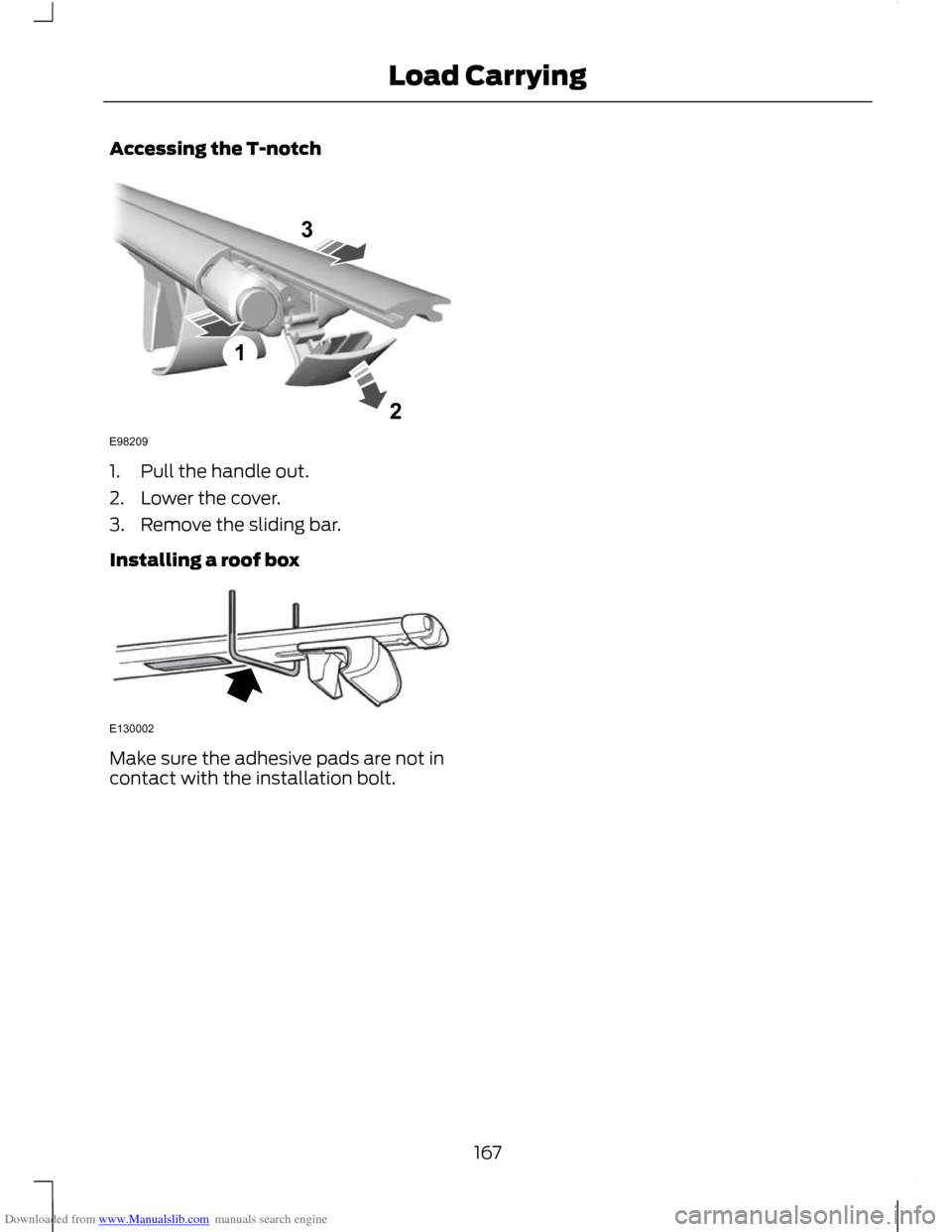
1. Pull the handle out.
2. Lower the cover.
3. Remove the sliding bar.
Installing a roof box
Make sure the adhesive pads are not in
contact with the installation bolt.
167
Load Carrying123E98209 E130002
Page 170 of 296
Downloaded from www.Manualslib.com manuals search engine TOWING A TRAILER
WARNINGS
Do not exceed 100 km/h (62 mph).
The rear tyre pressures must be
increased by 0.2 bar (3 psi) above
specification. See Technical
Specifications (page 209). Do not exceed the maximum gross
train weight stated on the vehicle
identification plate. See Vehicle
identification (page 214). CAUTION
Do not exceed the maximum
permissible nose weight, i.e. vertical
weight on the tow ball, of 75
kilogrammes (165 pounds). Note:
Not all vehicles are suitable or
approved to have tow bars fitted. Check
with your dealer first.
Place loads as low and central to the
axle(s) of the trailer as possible. If you are
towing with an unladen vehicle, the load
in the trailer should be placed toward the
nose, within the maximum nose load, as
this gives the best stability.
The stability of the vehicle to trailer
combination is very much dependant on
the quality of the trailer.
In high altitude regions above 1000 metres
(3281 feet), the stipulated maximum
permitted gross train weight must be
reduced by 10% for every additional 1000
metres (3281 feet).
Steep gradients WARNING
The overrun brake on a trailer is not
controlled by ABS. Change down a gear before you reach a
steep downhill gradient.
RETRACTABLE TOW BALL
CAUTION
Only move the tow ball arm with your
hand. Never use your foot or auxiliary
tools as damage to the mechanism
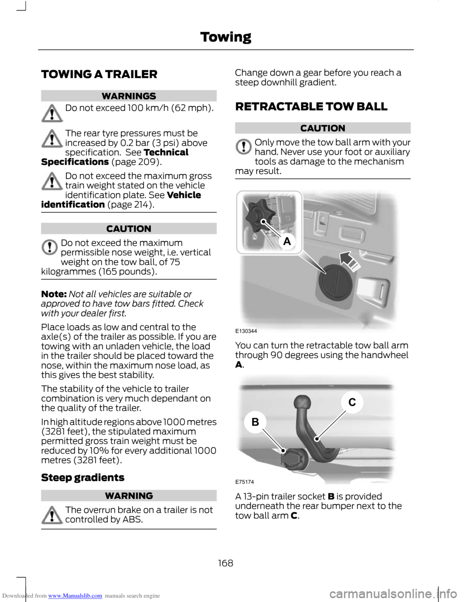
may result. You can turn the retractable tow ball arm
through 90 degrees using the handwheel
A.
A 13-pin trailer socket B is provided
underneath the rear bumper next to the
tow ball arm C.
168
TowingE130344A E75174BC