display FORD C MAX 2011 2.G Workshop Manual
[x] Cancel search | Manufacturer: FORD, Model Year: 2011, Model line: C MAX, Model: FORD C MAX 2011 2.GPages: 296, PDF Size: 7.87 MB
Page 157 of 296
Downloaded from www.Manualslib.com manuals search engine PRINCIPLE OF OPERATION
The camera is a visual aid for use when
reversing.
WARNING
The system does not relieve you of
your responsibility to drive with due
care and attention.
CAUTIONS
If you use a high pressure spray to
wash your vehicle, only spray the
camera briefly from a distance not
less than 20 centimetres (8 inches). Do not apply pressure to the camera.
Note:
Keep the camera free from dirt, ice
and snow. Do not clean with sharp objects,
degreaser, wax or organic products. Use only
a soft cloth.
During operation, guide lines appear in the
display which represent your vehicle's path
and approximate distance from rearward
objects.
USING THE REAR VIEW
CAMERA WARNINGS
The operation of the camera may
vary depending on the ambient
temperature, vehicle and road
conditions. The distances shown in the display
may differ from the actual distance.
Do not place objects in front of the
camera.
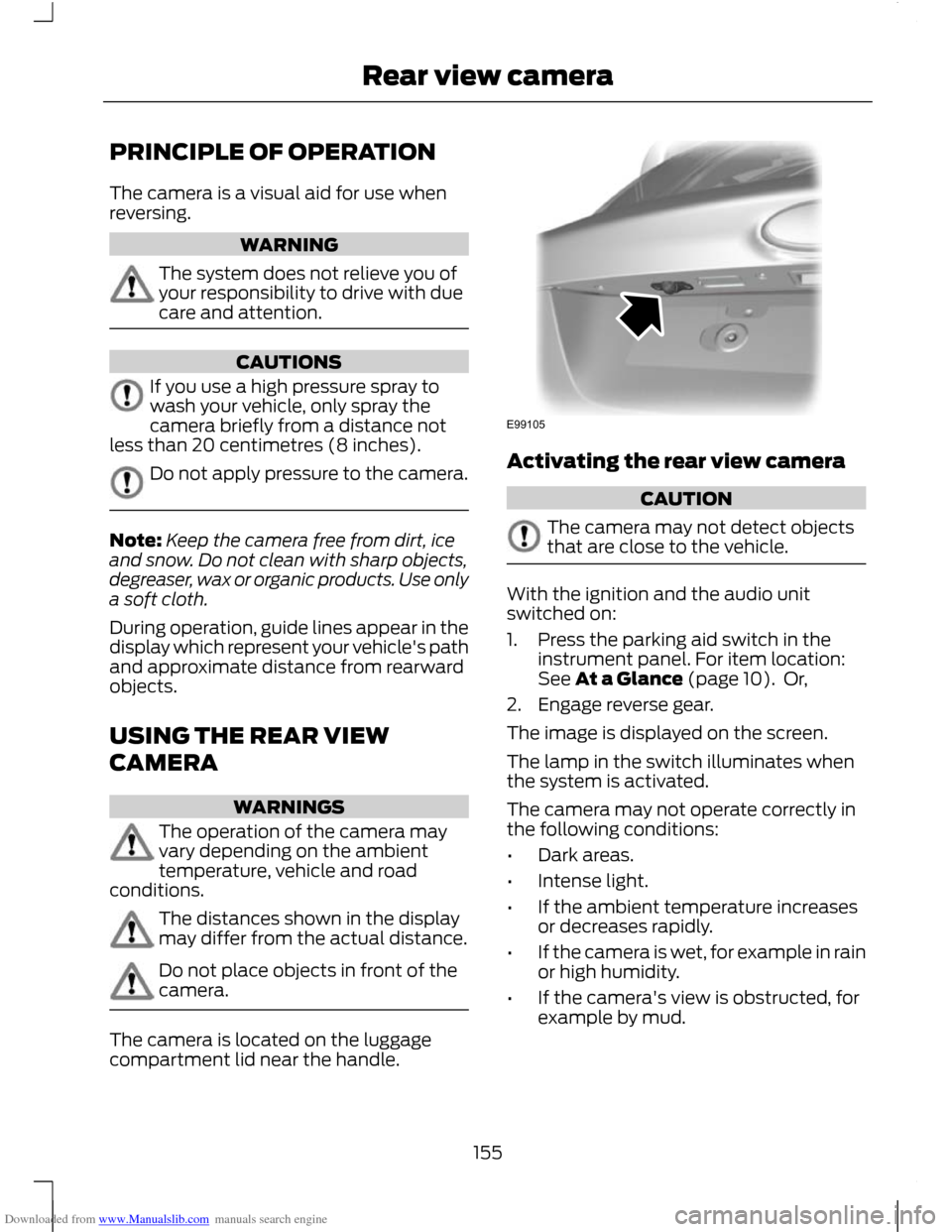
The camera is located on the luggage
compartment lid near the handle. Activating the rear view camera
CAUTION
The camera may not detect objects
that are close to the vehicle.
With the ignition and the audio unit
switched on:
1. Press the parking aid switch in the
instrument panel. For item location:
See At a Glance (page 10). Or,
2. Engage reverse gear.
The image is displayed on the screen.
The lamp in the switch illuminates when
the system is activated.
The camera may not operate correctly in
the following conditions:
• Dark areas.
• Intense light.
• If the ambient temperature increases
or decreases rapidly.
• If the camera is wet, for example in rain
or high humidity.
• If the camera's view is obstructed, for
example by mud.
155
Rear view cameraE99105
Page 158 of 296
Downloaded from www.Manualslib.com manuals search engine Using the display
CAUTIONS
Obstacles above the camera position
will not be shown. Inspect the area
behind your vehicle if necessary.
Marks are for general guidance only,
and are calculated for vehicles in
maximum load conditions on an even
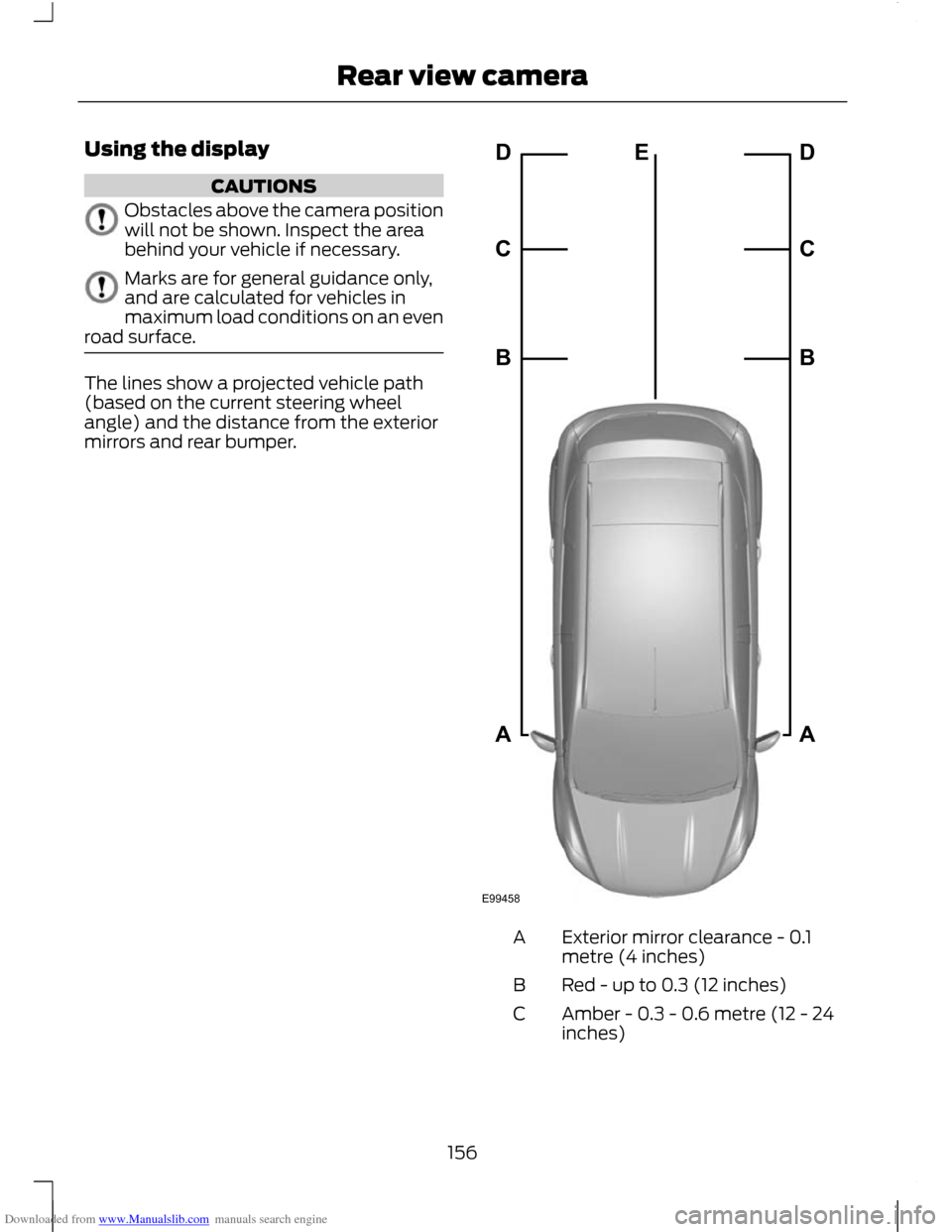
road surface. The lines show a projected vehicle path
(based on the current steering wheel
angle) and the distance from the exterior
mirrors and rear bumper.
Exterior mirror clearance - 0.1
metre (4 inches)
A
Red - up to 0.3 (12 inches)
B
Amber - 0.3 - 0.6 metre (12 - 24
inches)
C
156
Rear view cameraE99458ABCDEABCD
Page 159 of 296
Downloaded from www.Manualslib.com manuals search engine Green - 0.6 - 0.9 metre (24 - 35
inches)
D
Amber - centre line of the
projected vehicle path
E
Note: The green line is extended from 0.9
metre (35 inches) up to a distance of 3.2
metres (126 inches).
Note: When reversing with a trailer, the lines
on the screen are not shown. The camera
will show the vehicle direction and not the
trailer.
Deactivating the rear view camera
Note: Disengage reverse gear. The display
will stay on for a short period before
switching off.
Note: The system will automatically switch
off once the vehicle speed has reached
approximately 15 km/h (9 mph).
Press the parking aid switch in the
instrument panel. For item location: See
At a Glance (page 10).
Vehicles with parking aid
The display will additionally show a
coloured distance bar. This guide indicates
the distance from the rear bumper to the
detected obstacle.
These are colour coded as follows:
• Green - 0.6 to 1.8 metres (24 - 71
inches).
• Amber - 0.3 to 0.6 metre (12 - 24
inches).
• Red - 0.3 metre (12 inches) or less.
157
Rear view camera
Page 162 of 296
Downloaded from www.Manualslib.com manuals search engine PRINCIPLE OF OPERATION
WARNING
When you are going downhill, your
speed may increase above the set
speed. The system will not apply the
brakes but a warning will be given. The system allows you to set a speed, to
which the vehicle then becomes limited.
The set speed will become the effective
maximum speed of the vehicle, but with
the option to temporarily exceed this limit
if required.
USING THE SPEED LIMITER
Note:
The set speed limit can be
intentionally exceeded for a short period if
required, for example when overtaking.
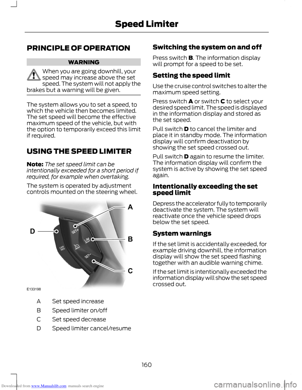
The system is operated by adjustment
controls mounted on the steering wheel. Set speed increase
A
Speed limiter on/off
B
Set speed decrease
C
Speed limiter cancel/resume
D Switching the system on and off
Press switch B. The information display
will prompt for a speed to be set.
Setting the speed limit
Use the cruise control switches to alter the
maximum speed setting.
Press switch A or switch C to select your
desired speed limit. The speed is displayed
in the information display and stored as
the set speed.
Pull switch D to cancel the limiter and
place it in standby mode. The information
display will confirm deactivation by
showing the set speed crossed out.
Pull switch D again to resume the limiter.
The information display will confirm the
system is active by showing the set speed
again.
Intentionally exceeding the set
speed limit
Depress the accelerator fully to temporarily
deactivate the system. The system will
reactivate once the vehicle speed drops
below the set speed.
System warnings
If the set limit is accidentally exceeded, for
example driving downhill, the information
display will show the set speed flashing
together with an audible warning chime.
If the set limit is intentionally exceeded the
information display will show the set speed
crossed out.
160
Speed LimiterE133198ABCD
Page 181 of 296
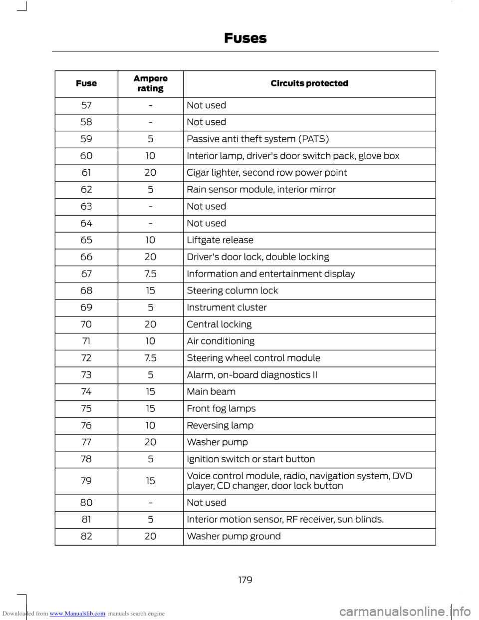
Downloaded from www.Manualslib.com manuals search engine Circuits protected
Ampere
rating
Fuse
Not used
-
57
Not used
-
58
Passive anti theft system (PATS)
5
59
Interior lamp, driver's door switch pack, glove box
10
60
Cigar lighter, second row power point
20
61
Rain sensor module, interior mirror
5
62
Not used
-
63
Not used
-
64
Liftgate release
10
65
Driver's door lock, double locking
20
66
Information and entertainment display
7.5
67
Steering column lock
15
68
Instrument cluster
5
69
Central locking
20
70
Air conditioning
10
71
Steering wheel control module
7.5
72
Alarm, on-board diagnostics II
5
73
Main beam
15
74
Front fog lamps
15
75
Reversing lamp
10
76
Washer pump
20
77
Ignition switch or start button
5
78
Voice control module, radio, navigation system, DVD
player, CD changer, door lock button
15
79
Not used
-
80
Interior motion sensor, RF receiver, sun blinds.
5
81
Washer pump ground
20
82
179
Fuses
Page 201 of 296
Downloaded from www.Manualslib.com manuals search engine GENERAL INFORMATION
CAUTIONS
Use only approved wheel and tyre
sizes. Using other sizes could damage
the vehicle and will make the National
Type Approval invalid. If you change the diameter of the tyres
from that fitted at the factory, the
speedometer may not display the
correct speed. Take the vehicle to your
dealer to have the engine management
system reprogrammed. If you intend to change the size of the
wheels from that fitted at the factory,
check the suitability with your dealer.
Note:
Check your tyre pressures regularly
to optimise fuel economy.
A decal with tyre pressure data is located
in the driver ’s door opening at the B-pillar.
Check and set the tyre pressure at the
ambient temperature in which you are
intending to drive the vehicle and when the
tyres are cold.
CHANGING A ROAD WHEEL
Locking wheel nuts
You can obtain a replacement locking
wheel nut key and replacement locking
wheel nuts from your dealer using the
reference number certificate.
Vehicles with a spare wheel
If the spare wheel is exactly the same type
and size as the other fitted road wheels,
you can replace the existing road wheel
with the spare wheel and continue to drive
in the normal manner.
If the spare wheel is different to the other
road wheels, it will carry a yellow label with
the appropriate speed limit. Refer to the following information before
changing the road wheel. WARNINGS
Drive the shortest possible distances.
Do not fit more than one spare wheel
on your vehicle at any one time.
Do not carry out any tyre repairs on
a spare wheel.
Do not drive through an automatic
car wash.
If you are unsure what type of spare
wheel you have do not exceed 80
km/h (50 mph).
Only fit snow chains to specified
tyres. See Technical
Specifications (page 209).
CAUTION
The ground clearance of your vehicle
may be reduced. Take care when
parking next to a kerb.
Note:
Your vehicle may exhibit some
unusual driving characteristics.
Vehicle jack WARNINGS
The vehicle jack supplied with your
vehicle should only be used when
changing a wheel in emergency
situations. Before using the vehicle jack, check
that it is not damaged or deformed
and that the thread is lubricated and
free from foreign matter. Never place anything between the
jack and the ground, or the jack and
the vehicle.
199
Wheels and Tyres
Page 210 of 296
Downloaded from www.Manualslib.com manuals search engine USING WINTER TYRES
CAUTION
Make sure that you use the correct
wheel nuts for the type of wheel the
winter tyres are fitted to.
If winter tyres are used, make sure that the
tyre pressures are correct. See Technical
Specifications (page 209).
USING SNOW CHAINS
WARNINGS
Do not exceed 50 km/h (30 mph).
Do not use snow chains on snow-free
roads.
Only fit snow chains to specified
tyres. See Technical
Specifications (page 209).
CAUTION
If your vehicle is fitted with wheel
trims, remove them before fitting
snow chains.
Note:
The ABS will continue to operate
normally.
Only use snow chains of 10 millimetre or
smaller.
Only use snow chains on the front wheels.
Vehicles with stability control
(ESP)
Vehicles with stability control (ESP) may
exhibit some unusual driving
characteristics which can be reduced by
switching traction control off. See Using
Stability Control (page 145). TYRE PRESSURE
MONITORING SYSTEM WARNINGS
The system does not relieve you of
your responsibility to regularly check
the tyre pressures.
The system will only provide a low
tyre pressure warning. It will not
inflate the tyres.
Do not drive on significantly
under-inflated tyres. This may cause
the tyres to overheat and fail.
Under-inflation reduces fuel efficiency, tyre
tread life and may also affect your ability
to drive the vehicle safely. CAUTIONS
Do not bend or damage the valves
when you are inflating the tyres.
Have tyres installed by properly
trained technicians.
The Deflation Detection System will alert
you if there is a change of air pressure in
any tyre. It does this by using the ABS
sensors to detect the rolling circumference
of the wheels. When the circumference
changes, this indicates low pressure in a
tyre, a warning message is displayed in the
information display and the message
indicator will illuminate. See Information
Messages (page 90).
If a low pressure warning message is
displayed in the information display, check
the tyre pressures as soon as possible and
inflate them to the recommended
pressure. See Technical Specifications
(page 209).
If this happens frequently, have the cause
determined and rectified as soon as
possible.
208
Wheels and Tyres
Page 211 of 296
Downloaded from www.Manualslib.com manuals search engine Apart from a too low tyre pressure or a
damaged tyre, the following situations can
affect the rolling circumference:
•
Vehicle load is uneven.
• When using a trailer or travelling up and
down an incline.
• Using snow chains.
• Driving on soft surfaces such as snow
or mud.
Note: The system will still function
correctly, but there may be an increased
detection time. System reset
Note:
Do not reset the system when the
vehicle is moving.
Note: You should reset the system
following any adjustment to the tyre
pressures or any changing of tyres.
Note: Turn the ignition on.
1. Using the information display control, navigate to Settings > Driver assist
> Deflation detection
2. Press and hold the OK button until confirmation appears.
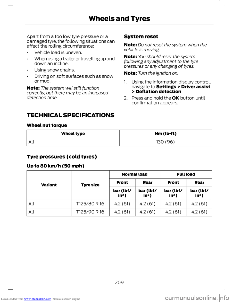
TECHNICAL SPECIFICATIONS
Wheel nut torque Nm (Ib-ft)
Wheel type
130 (96)
All
Tyre pressures (cold tyres)
Up to 80 km/h (50 mph) Full load
Normal load
Tyre size
Variant Rear
Front
Rear
Front
bar (lbf/in²)
bar (lbf/
in²)
bar (lbf/
in²)
bar (lbf/
in²)
4.2 (61)
4.2 (61)
4.2 (61)
4.2 (61)
T125/80 R 16
All
4.2 (61)
4.2 (61)
4.2 (61)
4.2 (61)
T125/90 R 16
All
209
Wheels and Tyres
Page 222 of 296
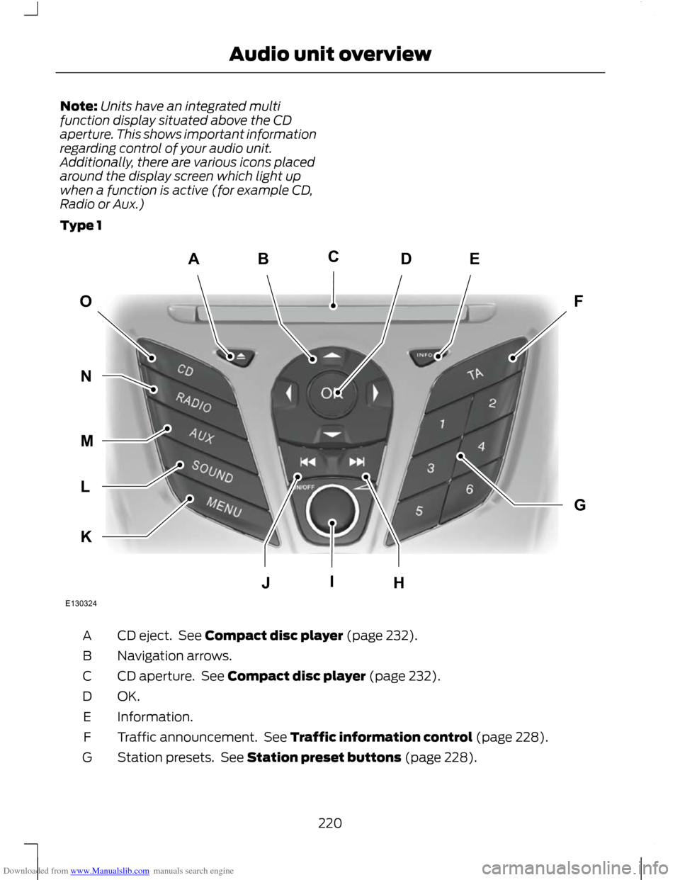
Downloaded from www.Manualslib.com manuals search engine Note:
Units have an integrated multi
function display situated above the CD
aperture. This shows important information
regarding control of your audio unit.
Additionally, there are various icons placed
around the display screen which light up
when a function is active (for example CD,
Radio or Aux.)
Type 1 CD eject. See Compact disc player (page 232).
A
Navigation arrows.
B
CD aperture. See Compact disc player (page 232).
C
OK.D
Information.
E
Traffic announcement. See Traffic information control (page 228).
F
Station presets. See Station preset buttons (page 228).
G
220
Audio unit overviewABEDFOGKLMNJHICE130324
Page 225 of 296
Downloaded from www.Manualslib.com manuals search engine On/off and volume control.
L
Seek down. CD track selection. See Station tuning control (page 227). See
Track selection (page 232).
M
Function 2.
N
Function 1.
O
Menu select.
P
Phone menu. See Telephone (page 237).
Q
Auxiliary, USB and iPod select. See Auxiliary input (AUX IN) socket (page
125). See Auxiliary input (AUX IN) socket (page 235). See Connectivity
(page 257).
R
Radio and waveband select. See Audio unit operation (page 227).
S
CD select. See Compact disc player (page 232).
T
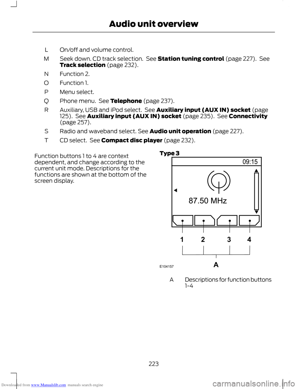
Function buttons 1 to 4 are context
dependent, and change according to the
current unit mode. Descriptions for the
functions are shown at the bottom of the
screen display. Type 3 Descriptions for function buttons
1-4
A
223
Audio unit overviewE104157A1234