FORD C MAX 2011 2.G Manual PDF
Manufacturer: FORD, Model Year: 2011, Model line: C MAX, Model: FORD C MAX 2011 2.GPages: 296, PDF Size: 7.87 MB
Page 71 of 296
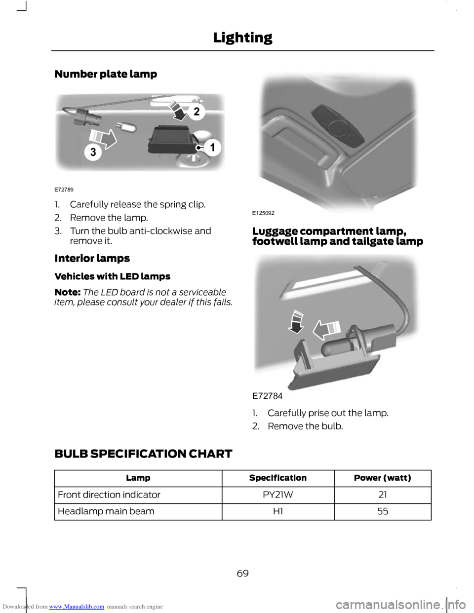
Downloaded from www.Manualslib.com manuals search engine Number plate lamp
1. Carefully release the spring clip.
2. Remove the lamp.
3. Turn the bulb anti-clockwise and
remove it.
Interior lamps
Vehicles with LED lamps
Note: The LED board is not a serviceable
item, please consult your dealer if this fails. Luggage compartment lamp,
footwell lamp and tailgate lamp
1. Carefully prise out the lamp.
2. Remove the bulb.
BULB SPECIFICATION CHART Power (watt)
Specification
Lamp
21
PY21W
Front direction indicator
55
H1
Headlamp main beam
69
Lighting321E72789 E125092 E72784
Page 72 of 296
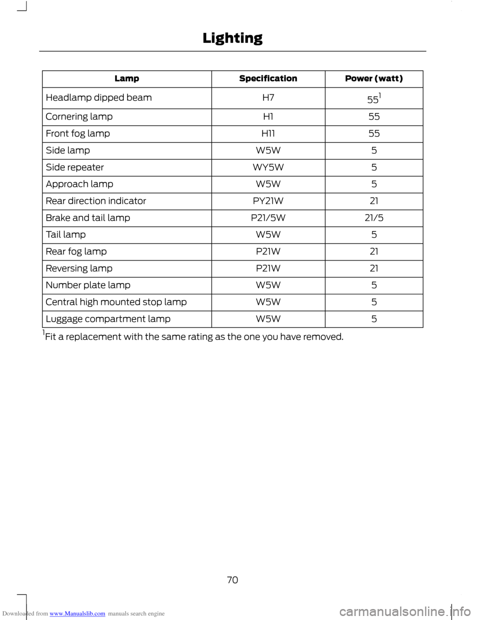
Downloaded from www.Manualslib.com manuals search engine Power (watt)
Specification
Lamp
551
H7
Headlamp dipped beam
55
H1
Cornering lamp
55
H11
Front fog lamp
5
W5W
Side lamp
5
WY5W
Side repeater
5
W5W
Approach lamp
21
PY21W
Rear direction indicator
21/5
P21/5W
Brake and tail lamp
5
W5W
Tail lamp
21
P21W
Rear fog lamp
21
P21W
Reversing lamp
5
W5W
Number plate lamp
5
W5W
Central high mounted stop lamp
5
W5W
Luggage compartment lamp
1 Fit a replacement with the same rating as the one you have removed.
70
Lighting
Page 73 of 296
Downloaded from www.Manualslib.com manuals search engine POWER WINDOWS
WARNING
Do not operate the electric windows
unless they are free from obstruction.
Note:
If you operate the switches often
during a short period of time, the system
might become inoperable for a certain time
to prevent damage due to overheating.
Switch on the ignition to operate the
electric windows.
Global opening and closing
You can also operate the electric windows
with the ignition off via the global opening
and closing function. See Locks (page
39).
Driver's door switches
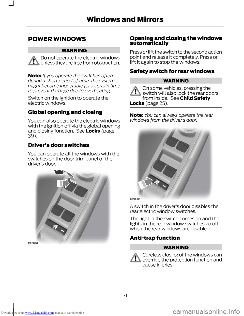
You can operate all the windows with the
switches on the door trim panel of the
driver ’s door. Opening and closing the windows
automatically
Press or lift the switch to the second action
point and release it completely. Press or
lift it again to stop the windows.
Safety switch for rear windows
WARNING
On some vehicles, pressing the
switch will also lock the rear doors
from inside. See Child Safety
Locks (page 25). Note:
You can always operate the rear
windows from the driver ’s door. A switch in the driver
’s door disables the
rear electric window switches.
The light in the switch comes on and the
lights in the rear window switches go off
when the rear windows are disabled.
Anti-trap function WARNING
Careless closing of the windows can
override the protection function and
cause injuries.
71
Windows and MirrorsE70848 E70850
Page 74 of 296
Downloaded from www.Manualslib.com manuals search engine The electric windows will stop
automatically while closing and reverse
some distance if there is an obstacle in the
way.
Overriding the anti-trap function
WARNING
While you close the window for the
third time, the anti-trap function is
disabled. Make sure there are no
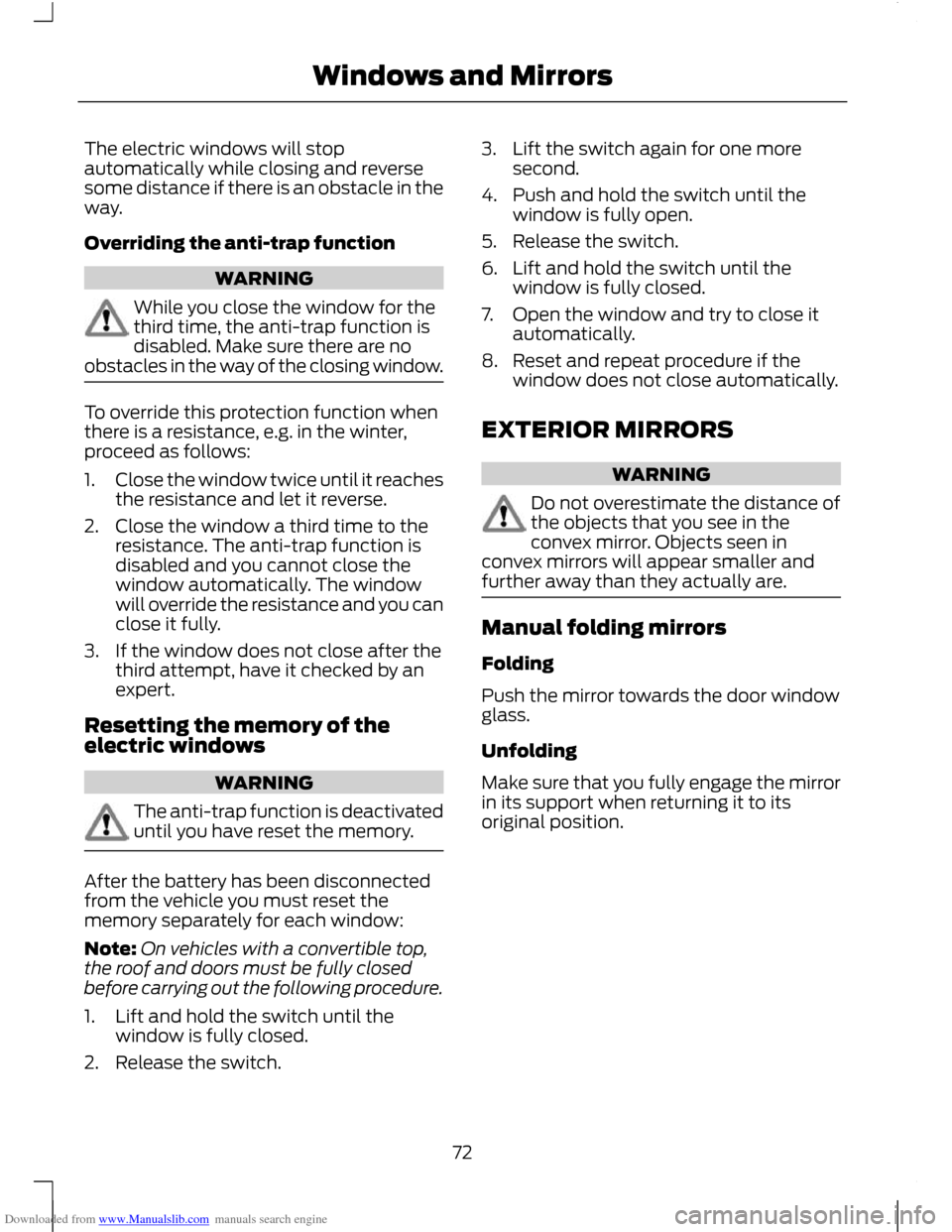
obstacles in the way of the closing window. To override this protection function when
there is a resistance, e.g. in the winter,
proceed as follows:
1.
Close the window twice until it reaches
the resistance and let it reverse.
2. Close the window a third time to the resistance. The anti-trap function is
disabled and you cannot close the
window automatically. The window
will override the resistance and you can
close it fully.
3. If the window does not close after the third attempt, have it checked by an
expert.
Resetting the memory of the
electric windows WARNING
The anti-trap function is deactivated
until you have reset the memory.
After the battery has been disconnected
from the vehicle you must reset the
memory separately for each window:
Note:
On vehicles with a convertible top,
the roof and doors must be fully closed
before carrying out the following procedure.
1. Lift and hold the switch until the window is fully closed.
2. Release the switch. 3. Lift the switch again for one more
second.
4. Push and hold the switch until the window is fully open.
5. Release the switch.
6. Lift and hold the switch until the window is fully closed.
7. Open the window and try to close it automatically.
8. Reset and repeat procedure if the window does not close automatically.
EXTERIOR MIRRORS WARNING
Do not overestimate the distance of
the objects that you see in the
convex mirror. Objects seen in
convex mirrors will appear smaller and
further away than they actually are. Manual folding mirrors
Folding
Push the mirror towards the door window
glass.
Unfolding
Make sure that you fully engage the mirror
in its support when returning it to its
original position.
72
Windows and Mirrors
Page 75 of 296
Downloaded from www.Manualslib.com manuals search engine ELECTRIC EXTERIOR
MIRRORS
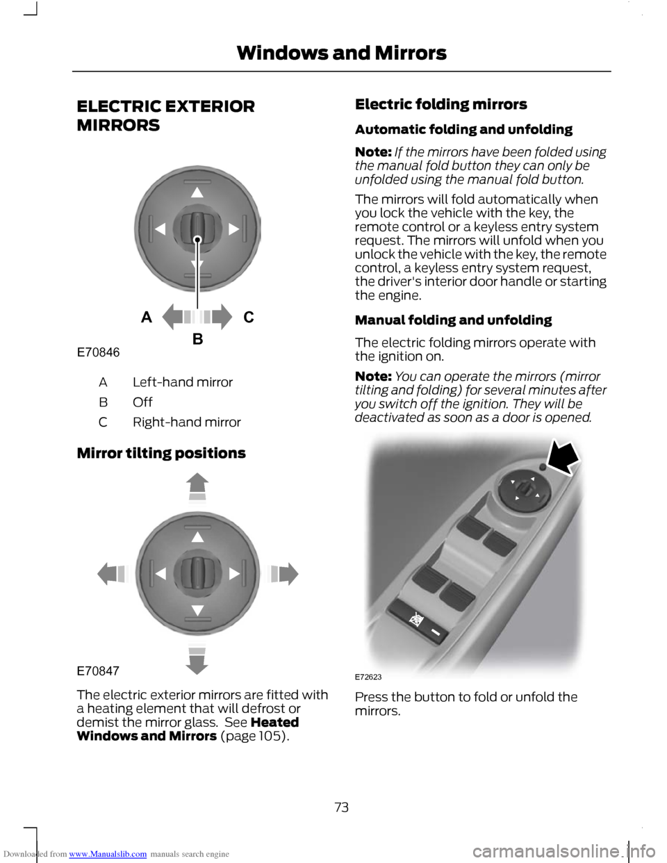
Left-hand mirror
A
OffB
Right-hand mirror
C
Mirror tilting positions The electric exterior mirrors are fitted with
a heating element that will defrost or
demist the mirror glass. See Heated
Windows and Mirrors (page 105). Electric folding mirrors
Automatic folding and unfolding
Note:
If the mirrors have been folded using
the manual fold button they can only be
unfolded using the manual fold button.
The mirrors will fold automatically when
you lock the vehicle with the key, the
remote control or a keyless entry system
request. The mirrors will unfold when you
unlock the vehicle with the key, the remote
control, a keyless entry system request,
the driver's interior door handle or starting
the engine.
Manual folding and unfolding
The electric folding mirrors operate with
the ignition on.
Note: You can operate the mirrors (mirror
tilting and folding) for several minutes after
you switch off the ignition. They will be
deactivated as soon as a door is opened. Press the button to fold or unfold the
mirrors.
73
Windows and MirrorsACBE70846 E70847 E72623
Page 76 of 296
Downloaded from www.Manualslib.com manuals search engine If you press the switch again while the
mirrors are moving, they will stop and
reverse the direction of movement.
Note:
When the mirrors are operated often
during a short period of time, the system
may become inoperable for a period of time
to prevent damage due to overheating.
AUTO-DIMMING MIRROR The auto-dimming mirror will adjust
automatically when hit by glaring light
from behind. It will not work when you have
selected reverse gear.
BLIND SPOT MONITOR
Blind spot information system
(BLIS)
WARNINGS
The system is not designed to
prevent contact with other vehicles
or objects. The system only provides
a warning to assist you in detecting
vehicles in the blind spot zones. The
system will not detect obstacles,
pedestrians, motorcyclists or cyclists. Do not use the system as a
replacement for using the side and
rear view mirrors, and looking over
your shoulder before changing lanes. The
system is not a replacement for careful
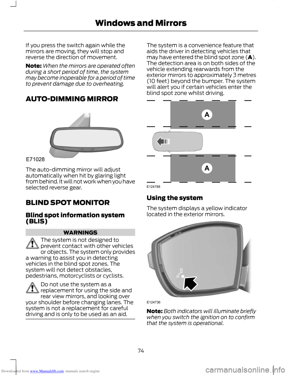
driving and is only to be used as an aid. The system is a convenience feature that
aids the driver in detecting vehicles that
may have entered the blind spot zone (A).
The detection area is on both sides of the
vehicle extending rearwards from the
exterior mirrors to approximately 3 metres
(10 feet) beyond the bumper. The system
will alert you if certain vehicles enter the
blind spot zone whilst driving.
Using the system
The system displays a yellow indicator
located in the exterior mirrors.
Note:
Both indicators will illuminate briefly
when you switch the ignition on to confirm
that the system is operational.
74
Windows and MirrorsE71028 AAE124788 E124736
Page 77 of 296
Downloaded from www.Manualslib.com manuals search engine Note:
On vehicles with automatic
transmission, the system is active only in S,
D and N.
The system is only active when you exceed
10 km/h (6 mph). The system is
temporarily deactivated when you select
reverse gear.
System detection and alerts
The system will trigger the alert for vehicles
that enter the blind spot zone from the rear
or merge from the side. Vehicles that you
pass, or vehicles that enter the blind spot
zone from the front, will only trigger the
alert after the vehicle has remained in the
blind spot zone for a short period of time.
Note: Vehicles that pass through the blind
zone quickly (typically less than 2 seconds)
will not trigger the alert.
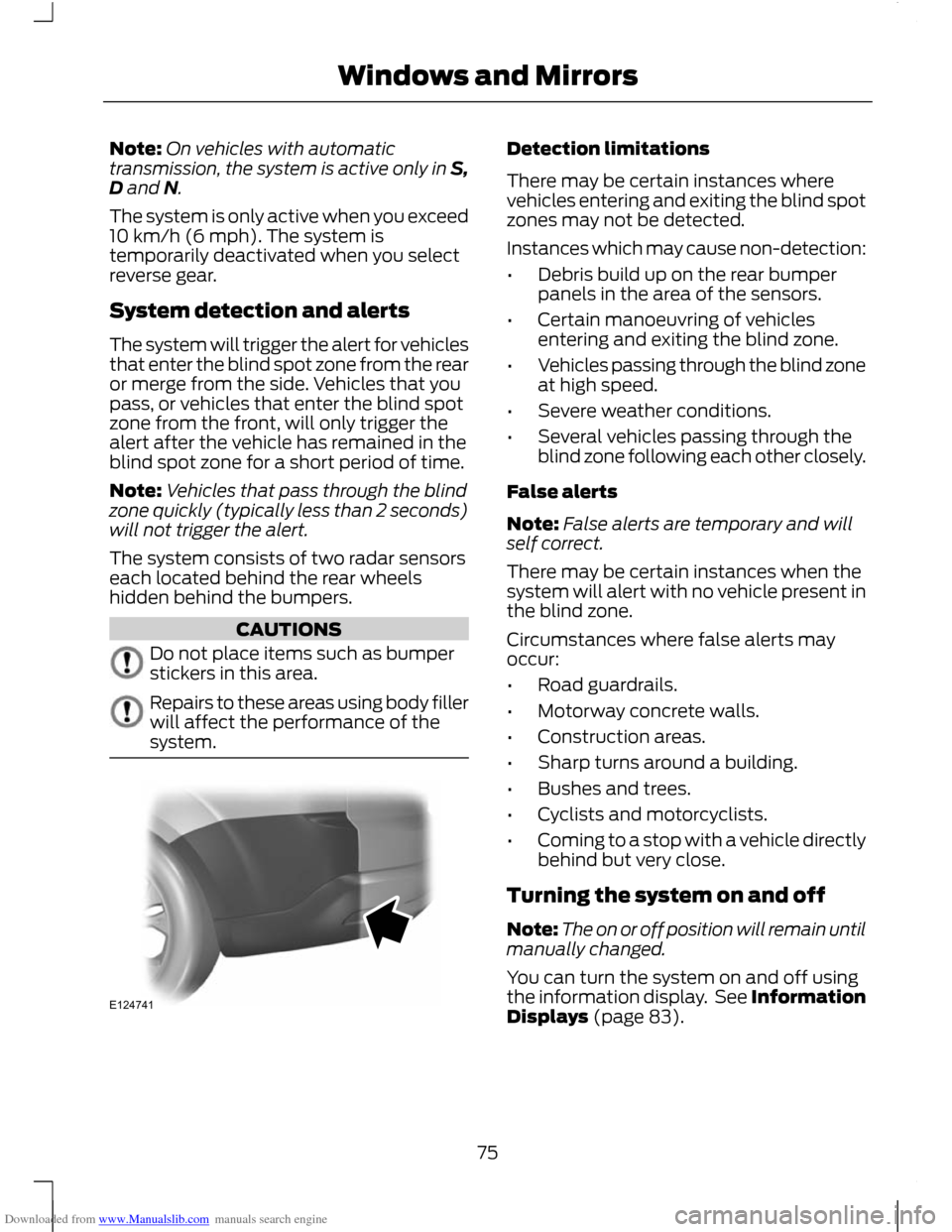
The system consists of two radar sensors
each located behind the rear wheels
hidden behind the bumpers. CAUTIONS
Do not place items such as bumper
stickers in this area.
Repairs to these areas using body filler
will affect the performance of the
system. Detection limitations
There may be certain instances where
vehicles entering and exiting the blind spot
zones may not be detected.
Instances which may cause non-detection:
•
Debris build up on the rear bumper
panels in the area of the sensors.
• Certain manoeuvring of vehicles
entering and exiting the blind zone.
• Vehicles passing through the blind zone
at high speed.
• Severe weather conditions.
• Several vehicles passing through the
blind zone following each other closely.
False alerts
Note: False alerts are temporary and will
self correct.
There may be certain instances when the
system will alert with no vehicle present in
the blind zone.
Circumstances where false alerts may
occur:
• Road guardrails.
• Motorway concrete walls.
• Construction areas.
• Sharp turns around a building.
• Bushes and trees.
• Cyclists and motorcyclists.
• Coming to a stop with a vehicle directly
behind but very close.
Turning the system on and off
Note: The on or off position will remain until
manually changed.
You can turn the system on and off using
the information display. See Information
Displays (page 83).
75
Windows and MirrorsE124741
Page 78 of 296
Downloaded from www.Manualslib.com manuals search engine When you turn the system off no further
alerts will be received. The BLIS warning
indicator will illuminate. See Warning
Lamps and Indicators (page 79).
Detection errors
Note:
The alert indicator in the mirror will
not illuminate.
If the system senses a fault on either
sensor, the system warning symbol will
illuminate and remain on. The information
display will confirm the fault and indicate
whether the left or right side is affected.
Blocked sensor WARNING
Prior to the system recognizing a
blocked condition and issuing a
warning, the number of missed
objects will increase. CAUTION
The sensors may not detect vehicles
in heavy rain or other conditions that
cause disruptive reflections.
Note:
Keep the rear bumper area
surrounding the sensors free from dirt, ice
and snow.
If a sensor becomes blocked the system
performance may degrade. A blocked
sensor message may be displayed.
The system will automatically return to
normal operation once two other vehicles
have been detected on both sides. Trailer towing false alerts CAUTION
Vehicles fitted with a trailer tow
module not approved by us may not
correctly be detected. Switch the
system off to avoid false alerts. See
Information Displays (page 83). If the vehicle is fitted with a trailer tow
module approved by us, the system will
detect a connected trailer and deactivate.
A confirmation message will be shown in
the information display. See Information
Messages (page 90). The BLIS warning
indicator will illuminate. See Warning
Lamps and Indicators (page 79).
76
Windows and Mirrors
Page 79 of 296
Downloaded from www.Manualslib.com manuals search engine GAUGES
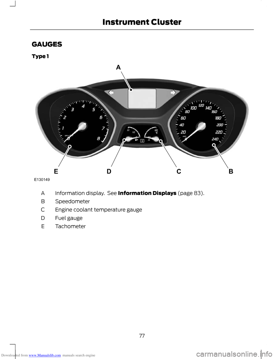
Type 1
Information display. See Information Displays (page 83).
A
Speedometer
B
Engine coolant temperature gauge
C
Fuel gauge
D
Tachometer
E
77
Instrument ClusterBCDEAE130149
Page 80 of 296
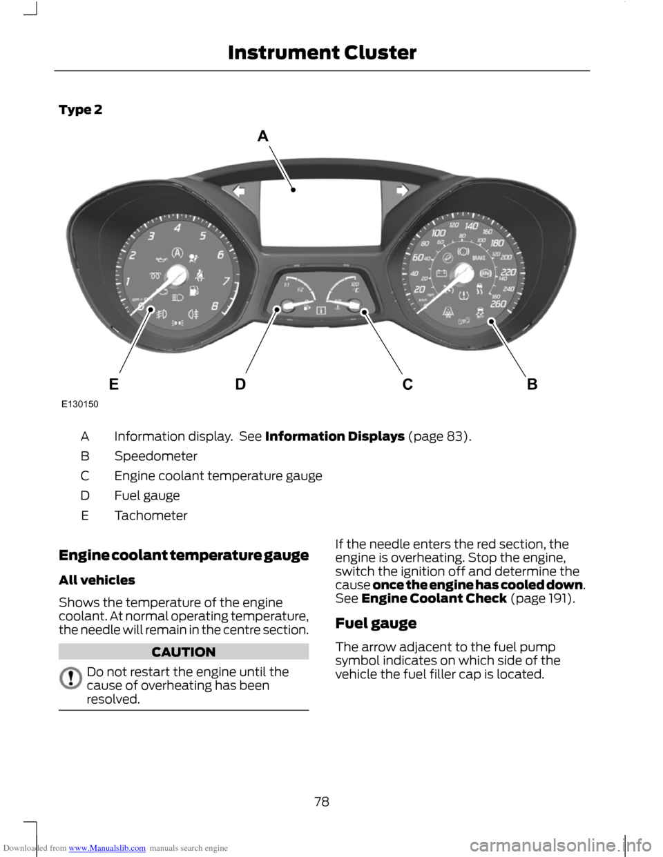
Downloaded from www.Manualslib.com manuals search engine Type 2
Information display. See Information Displays (page 83).
A
Speedometer
B
Engine coolant temperature gauge
C
Fuel gauge
D
Tachometer
E
Engine coolant temperature gauge
All vehicles
Shows the temperature of the engine
coolant. At normal operating temperature,
the needle will remain in the centre section. CAUTION
Do not restart the engine until the
cause of overheating has been
resolved. If the needle enters the red section, the
engine is overheating. Stop the engine,
switch the ignition off and determine the
cause once the engine has cooled down.
See Engine Coolant Check (page 191).
Fuel gauge
The arrow adjacent to the fuel pump
symbol indicates on which side of the
vehicle the fuel filler cap is located.
78
Instrument ClusterBCDEAE130150