ECO mode FORD CAPRI 1974 User Guide
[x] Cancel search | Manufacturer: FORD, Model Year: 1974, Model line: CAPRI, Model: FORD CAPRI 1974Pages: 205, PDF Size: 43.75 MB
Page 151 of 205
,
.00 Chapter 9 Braking system
PR IMARY CUP
SeCONDARY J CUP _ RETA INER SCREW
INTERMEDIATE RING
SECONDAR Y CUP)
STOP WASHEP. WASHE R
PRIMARY ~ (''''')
CUP PISTON ~lJ ~
SPRIN\G SEAT T 1 WAStE:~L~\C Q I~
PRl~lARY CUP ./
SPRING OISC I -1 '" "'~'f" SPRING i SEAT L ,:-\,/(.'.~·, J ' '
RETAINER • \ . '0 I)J-'0'.'.)'. ',:.,' "'f
I -, " ,O"'j')'" I' . I r -h" .
l J i\\"\" ,jl;
~G«1N w: 1 vl";';':' ~ .. '
" r • • {l"t:';" ,: .• ,-; \{. . ' SNAP . \J, ~;'. PISTON RING
--
1\-\1 ijM:\'.' ,J , ~1.1"9 _ ·S TOP SCREW .....
--
SEAL ','
-'---
WASHEA
---, ,
/ /
SECONDARY CUP
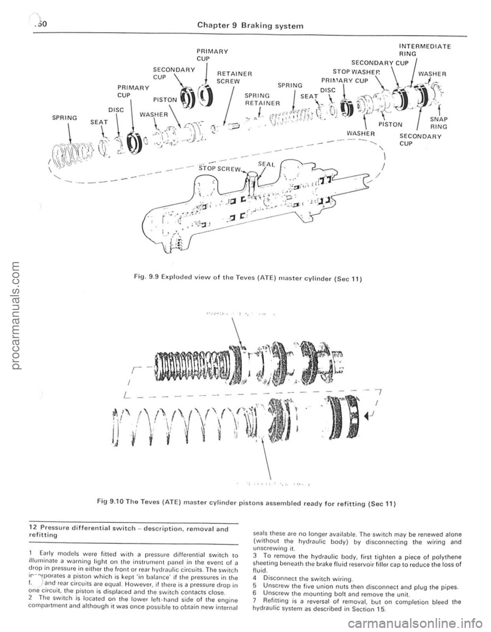
Fig. 9 .9 EKplodcd view of tho Teves (ATE) master cylinder (Sec 11)
, •..•.• -." . I',
- --
I
'-- ----
---"Ii
-,
I
~J
- . ' , ..... (
F ig 9.10 The Tavos (ATE) maste r cylinder pisto ns as sembled ready fo r reliUing (Sec 11)
12 Pressure di Herent;al switch -desctilHion. removal and refitting
E,lrly mOdels were filled with a pre ssure diHerent ial switch to illurnin~to ~ wolfning l igh t on the in stru men t pilnel in the event 01 a drop in preSsure in eithe/the Iron t 0/ rear hydraul ic circui ts . The switch ir- "'rporates 1I piSton which is kept 'in b alanco' if the pres sures in tho I. and roar ci,cui ts are equal. Howeve/, rl there is a pressure drop in
one circuit. t he pisto n is displaced and the switc h con tacts close .
2 The switc h is loca ted on tha lowe, left .hand side of the eng ine comp,Htrnent and a lthough it was once possible \0 obtain new in ternal
seals these are no longer available. Th e switch may be renewed alone (without Iho hyd,au lic body) by disconnecting the wiring and unsc rewing it .
3 To rernovo the hydraulic body. first tigh t
en a piece 01 polythene shoetinu bene ath th e brako Iluid reservoir fillor cap 10 reduce th a loss 01 fluid .
4 D isconnec t the swit ch wiring.
5 Unscrew the fi
ve union nuts thon disconnec t and plug the pipes.
6 UnSCfew the mouming bolt and romove the unit.
7 Relillin g is a reversa l of removal. but on comple tion bleed the hydraulic system as described in Section 15 .
procarmanuals.com
Page 154 of 205
Chapter 9 Braking syste'm 153
3
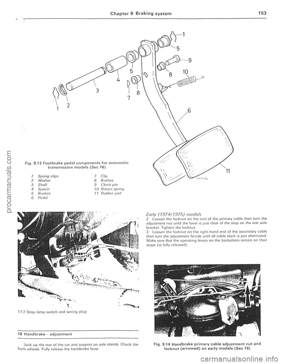
Fig, 9 .13 Foothr
Spring clips 7 Clip 2 Washer 8 Bushes 3 Shafl 9 Clevis " in , Spacer 10 Rdl/fn sp,illY
5 Bushes /I Rub/u."r P,lI/
6 Pl1d;1I
172 Stop lilOlP switch iHld witi:lg plug
18 Handbrake -adjustment
)Jack up the ,e
11
Early (1974/1975) models 2 loosen the locknul on the end 01 the primMY c
3 Loosen the locknul on the IIgill·hnnd end 01 the secondnry cable then IUfn the adjustment le"ule until
, .,
" I
,
t , t
i
J
I
i
J
I
procarmanuals.com
Page 155 of 205
)4 Chapter 9 Braking system
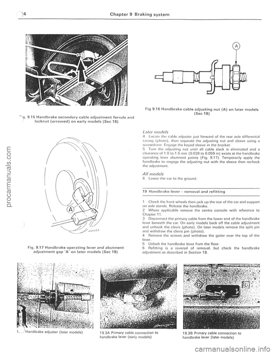
Fig 9 .16 H an dbrak8 cable adjusting nul (A) on later models (Sec 18) ~'9. 9 .15 Handbrako secondary cable adjustment fonu le and lockn u t (arrowed ) on early models (Soc 18)
I
Fig. 9 .17 Hnndhrnke operating lover n n d (llwtment (ldjuSlment gn p ·A' on later models (Sec 18)
'-iller mode!!s 4 LO(:,'I" trw r.al,lo .1dlUS1Cf lust forWi1f(1 01 the 10." axle dillCrcntinl , ;;.~.IIl!J (,.holn). then Sflp,l'ate Ihe ndjus\ing nul and sio eve usinIJ II se.ewtl""cr ["n,'IIO lhe keyed sleove in the bracket.
5 T 11m Ihe lldlu sling nul unlot all c.,l>lo slilc k is eliminated and a cleiuallr.e of I 0 '0 1 5 mill (0.039 to 0.059 in) exists at tho handb'Jke ope.aling 10l'm .. butment points (Fig. 9.17) Temporarily apply the holn(i!),,,kc 10 cnUage t he ilujus\ing nut with the sleeve then recheCk the ildJuSlmcnt.
All models 6 Lower Ihe r.'lr In the ground.
1 9 H ,1"dbrako lover -removal and refilling
Chock till) front whecls then lack l'P thO tcat 01 t he Cllt and SUllport on ilxlc swnds . Rclc~!se the halldbmko . 2 Whete applicahle remove the centre console with reference to Chapter 11.
3 Disc;onnecl the l>fiOlilJy cable from the lower end of t he h andbrilke
lever beneath the etlr . On early mooels baek all the cable adjustmen t
and unhook the c lev is (photo). On lale r m odels remove the splil pin and withdtaw the clevis pin (photo). <1 Remove the SCHlWS and withdraw the gaiter over the top 0 1 th e lever.
S Unbol t the hanrlhtake lever Irom the lIoot. 6 Relinin g is a revetsal 01 removal, but check the handbHlke
ildjustment as desClibed in Section 18 .
19 .
3A Prim ary cable connection to
handbtake lever (early models) 19.39 p.ima.y cable connection 10 handbrake leve r (Iale. models)
procarmanuals.com
Page 157 of 205
,
156 Chapter 9 Brakin g syste m
Secondary cc1ble (early models) 5 Loosen 1I1c lock.nut ~nd unscrew the adju stment ferrule from the right-hand rear clevis.
6 Remove the split pin and clevis pin securing the secanda.v caulo \0 the left-hand Icar operating le ve l. 7 htrac the clip, remove the clovis pin. and withdraw the pullcy wheel from the lever on the Ical a~le. 8 Remove Ihe cable from the lever.
Transverse rod (later models) 9 Disconne ct the cable from the righi-hand rear opCfating Icvcr by
removing the split pin and clovis pin. to Uncl.p the cable hom the 'Hlnsvcrse rod . 11 Remove Iho spli, pin and clevis pin securing the fod 10 the Icft·h~nd le;!1 operating lever . 12 Slide the transverse rod Irom the guide on the rOM axle . 13 Check thO {luide bush lor wear and dama ge and renew It il necessary by prising il oul and pressing a new bush irllo POSilioll.
All models 14 Refining is a r e versa' of removal. but lubr icllto the lin kage as )scflhed in Section 2, and atljl' stthe cable as (fescri bed in Section 18.
21 VilCUUrll sorvo unit -dosCrilHion
A vacuum servo unit is linod Into the lir,lk e hydrallirc cil cu il. 111 series with I he 111,1S ler cylinde f. to provide assiswnco to the dllver whlln Ihe brake pedal is depressed . Thi s reduces the eHolI le{luired try the driller to oper,lIe the brakes, under all brak ing condi tions .
This unit operates by vacuum, obtained from Ihe indu ction mnni rold and comprises basicall y iI booster diilphragnl and check lIallle . The servo unit and hydraulic master cylinder are connected
t o gether so that th e serllO unit piston rod acts as the master cylrnder pUShrod. The driller's b rilking ellon is trilnsmitted through allot her PIi ShlOd 10 the serllO unit piston and ils built-in COmrol system . The scrllo unll pislon docs not fit tightly inro the cylinder. but has a strong ,lltl flhril!Jlllto ke el) liS edges in COllst ilnt COntaCI with I he cylinder Willi_
23 rilult diagnosis -hrilking system
~ylllptom
-'ceSSllle ped,,1 u;tllel
nrakcs pull 10 ono Side
Or;tke ludder
E~cessive eHor l to stop car
so ensuring an i1inigh t seal between the two parts, The fo rward
chamber is held undelllaCUUm condi tions cleilted in the inle t manifold of the engine and during periods when the brake pedill is not in use, the controls open a passtlge 10 the rear ch ambe ., so placing it under lIacuum conditions as well. When the b.ake pedal is dep.essed. the lIacuum pass.Jge to the rear chamber is CUI oH and the chamber expos ed to atmospheric pressure. The consequent rush 01 ail pushes
the servo piston lorward in tile lIacuum chamber and operates the main push rod to the m.Jster cylindcl. The controls are designed so that assistance is given under all condllions. When the brakes are 1'101 requ ired, vacuum in the rear chamuer i s .e -es tabl ished when the br.Jke ped.J1 is released . All air Irom the atmosphe.e entering tho rear ch.Jmbe. is passed through II sma ll air trlter. Und er normal opcr.Jting cond itions tho IIflC(IUm serllO unit is lIery relraule and does not require ollerhaul e~cepl at IIcry high mile,1geS. In this case it is far bcner 1 0 o bta in a serllice e~hange uni l. r,1the, than rcp;ti . the o,igi'lo11 unit . Although inlernal components we,e once .Jv'lIlaule 10 ' ovcrhauling purposes this service has no w been
d,scont,nue(t .
22 Vacuulll servo unit _ remOlla l MId re filtillg
I RemOIlO the master cylinder as desc.ihed In Section 10. 2 D,scolllwc l thc vacuum hose from the non·return lIalve on the serllo \lI1it. 3 Work i,,!) insido thc cal. remOlle th e lower l;t cia panel below the stccring column. 4 E~tractlhc clip and l)ul1 outlho clellis pin attaching Ihe push.od to the l ootu .ake ped;t!. 5 Unsc.ew the nuts securing thc mount ing b.ack.et to the bulkhead.
then withdraw thc serllo unit and bracket from the engine COlllp,lJtlnen t, 6 UnSClew th e nuts ar1(1 serlar,lle the braket 110m the SCIIIO uni, . 7 netrning IS;t rell e.sal 0 1 remOllal w ith leference .Jlso 10 Section 1 0 when retrumg Ihe master cylrnder.
Renson(s)
RC.Jr blake self adju sting mechanism faulty All i n hydrilulic system
WOIll or cont,llllina led /rnin{Js Seized Caliper or wheel cy linde r
E~cessille run-out or distortion of discs o. drums
Worn Of cont aminated linings Brake backplate or caliper l oose WOIll suspensio n bailloints
SerllO unit faulty
Worn or conwmin.Jted linings
I
J
procarmanuals.com
Page 177 of 205
)76 Chapter 11 Bodywork and fitting
General description
The body is of all-s teel welded construction with impact ilbsorbing hont Dnd rear sections . Anli-burSllocks nrc lilted 10 the doors, ilnd the
t ailgDte is supponcd by \J
AI the in1erVills speCIfIed in the Routine M"IIl\cnilnCe section in the front 0 1 the nl
Check underbody protective coatiog 5 W,th the CM supponed on i1xle stilnds. check the cond,tlon 01 the un(lelbody protcctivc coating. i1nd wherc neceSSilry clean
M,,;ntcll
Wily to remove any aCCUIllUI,lted mud whIch WIll retillll mOlslu re
Mats and C
very line culling pils te. Finally, opply wax polish. WhNe the scrotch has penctrDt(ld right through to the metill of the bodywork. causing the mowl \0 rust. iI d ifferent repa ir lechnique is
required. Remove any loosc rus t fronl the bottom 01 the scra tch with a penknile. then apply rUSI inhibiting paint 10 prevent the lormation 01 rust in Ihe future. Using n rubber or nylon appliCiltor fill the scratch with bodystopper paste. II requ ired. this paste Ciln be mixed with cellulose thinners to provide a very thin paste which is ideal for filling narrow scratches. Before t he stopper·paSI(l in the scratch hardens. wrilp il piece 01 smooth COllon rJg i1round the lOp 01 J linger. Dip the finger in cellulose thinners and then quickly sweep it i1CIOSS the surlace of the 5topper-pJste in the scratCh: this will ensure tha t the surfilce 01 the stopper,pilste is slightly hollowed. The scratch can now be p
first wsk is to pull the dent out, untrl t he affected bodywork almost
procarmanuals.com
Page 179 of 205
17 8 Chapter 11 B odywork and fitting
If the owner is renewing ~ complete component himself. he will be left with the problem of IlIldmg a sUI1
Major u o d y damage - repair
Where serious danHlge has or.cur",d or la,ue aW
Ir
Loose door or window winde, ",,,,dft,!; (Ii) Loose 0' lIIiS.lliUned d(Jo, lock c(lillj/olJC!lJl~ (c) Loose or worn relllOle con/iol ""."/."";",i$III
2 It IS quite possrule 10' r,rllies 10 he the ",suit of" [O,,,lrrllirl,Orl 01 111<.1 atrove laullS. so a c;,r(:/ul <.1xanrrrr;riron should he rn",h, 10 ilCIl'UllU1e III<, exact CillrSf:! 3 If
)
7 .3 Door striker plate
f ,i
j
I
j
I
\:
it
1
(.'----+"<, --'-1 ------<0
00>-----1\.. -~--.
F i!J.1l.1 A lignin!J the s triker 10 lock support plnte (Sec 7)
Edyes A and lJ shoold be 1'.1(.lllel
A
'0- - -- . ,
,'---I.::i.I I ,
--/
F ig 11.2 Lock claw·to·striker cleiHance (Sec 7)
A -70,11111 (028111)
5 Wrlh t he lock in the open positron. check the lock cl
8 Bumper s -removal nnd refitlin g
FrOIll bumpN 1 D,sconnect the u<.rttery earth lend. Also where necessary dis connect the IIldrC
Rear bUll/pel 5 Open the lJ.tgate. Ihen rernOve the mal ilnd the sub·floor. G Remove the Jack ilnd washer water reservOIr (where applrcable) . 7 Remove the two nuts. Sp",l(J wilsher and 11m wilshers.
Page 202 of 205
inlet manifold - 83
main system components remova l and refilling -80 m~intenilnce, routine -79
specificiltions -67 to rque wrench settings -67 Fuel pump carburettor system cleaning - 68 re moval and refilling - 68
testing -68
fuel inject ion system removal and refining -80 Fuel system (carbureUor) accelera tor cable -74
accelerator shah and pedal - 75 air cleaner - 68
carburetlor -66, 68 to 73
description -67 e~ haust manifold - 76 lault diagnosis -85 luel pump -68 fu el wnk -73, 74 fu el lan k fille r pipe -74 fuel tank sender unit -74 inle l manifold -75 mainte nance, routine -67 specifiCiltions -66 torque wrench senings - 67 Fue l tank cleaning and repai r -74
filler pipe removal and re fi\ling .-74 remova l and refilling -73
sender uni t removal and ref il\in g -74 Fuel tank sender unit (fuel injection models) -83 Fuses
G
general -220 specifica tio ns - 199
Gearbo~ see Manual gearbO K Gudgeon pins - 37. 52
pdbrake adjus tment -153 cable(s} and rod removal and refilling 155 lever removal and refitting -154
warnin g hght switc h -225 Headlights alignment - 212 assembl y: removal and refilling ~ 211 bulbs renewal-2 13 Heater assembly: diSI11(lntting and reassembly 8ehr - 19 4 Smiths standard and heavy duty -196 assembly: removal and ret.tting -193 contlols
adjustmen t -192 removal and refilling ~ 1 93 water valve (heavy dUly heater)
removal and re fitting - 193 History o f tho nlodal-5 Horn faul t tra cing . remova l and refilling -220 Hubs, front
bearings renewal -162 removal. ret lu in g and bearing adjustment -16 1 Iraulic systam (brakes) bleed ing - 152 pipes and hoses removal and refilling -151
Index
Ignition switch and lock -224 Ignition system -87 el seq Ignition sys tem amplrlier module (2 .8 l i\(e mode ls)
r emova l and refilling - 94
condenser (3. 0 litre models) -90 COntact bre aker points (3.0 litre models) - 89
description -88
dis tributo r -
90. 92. 93 fau lt diagnosis -96
firing order -87 mainteMnce. routine -88
spare plugs - 91. 95 speci fications -87
t im ing -94
torque wrench settings -87 In strument cluster ill umina tion switch -224 removal and refitting _ 221 Instrument voltage regulator removal and refilling -226 Interior lamp and bulb
removal and refilling -217
J
Jacking -7
L
lubricants and fluids recommended - 17 lubrication chart - 17 lubrication system
M
2.8 litre engine -39 3.0 litre engi ne -53
Main and big·eOld bO(lrings e~amination and renovation -37, 52 Main bearings (3.0 litro engine) removal - 51 Maintenanco , routine bodywork and fillings d oor ch ec k straps security check - 16 locks, door chec k Straps. tuellilte r C
h andbrake linkage lubricat ion -16, 144
h ydraulic fluid levul check /lap up - 16 . 143 hydraulic flu id renewal -16. 144
line s and hoses check -16
pads ilnd shoes we." check -16 , 14 3 servo check -16 . 144 vacuum hose check -16 Clutch adjustment chock -16, 98 cooling syslem
coolan l leve l chec k/top up -16, 59 coolant renewal -16, 59 drivebelt condl tion/wnsion check -16, 59 leaks check - 59 electrical system
ballery elec tro lyt e leve l cheek /top up - 16. 200 equ ipmen t opera tio n check -16. 200 headlamps cleaning -16
253
'i
'" , '.;.l
•
procarmanuals.com