FORD F250 SUPER DUTY 2017 Owners Manual
Manufacturer: FORD, Model Year: 2017, Model line: F250 SUPER DUTY, Model: FORD F250 SUPER DUTY 2017Pages: 642, PDF Size: 12.35 MB
Page 351 of 642
Make sure that you dispose of old batteriesin an environmentally friendly way. Seekadvice from your local authority aboutrecycling old batteries.
If storing your vehicle for more than 30days without recharging the battery, werecommend that you disconnect thebattery cables to maintain battery chargefor quick starting.
Battery Management System (If
Equipped)
The battery management system monitorsbattery conditions and takes actions toextend battery life. If excessive batterydrain is detected, the system temporarilydisables some electrical systems toprotect the battery.
Systems included are:
•Heated rear window.
•Heated seats.
•Climate control.
•Heated steering wheel.
•Audio unit.
•Navigation system.
A message may appear in the informationdisplays to alert you that batteryprotection actions are active. Thesemessages are only for notification that anaction is taking place, and not intended toindicate an electrical problem or that thebattery requires replacement.
After battery replacement, or in somecases after charging the battery with anexternal charger, the battery managementsystem requires eight hours of vehicle sleeptime to relearn the battery state of charge.During this time your vehicle must remainfully locked with the ignition switched off.
Note:Prior to relearning the battery stateof charge, the battery management systemmay temporarily disable some electricalsystems.
Electrical Accessory Installation
To make sure the battery managementsystem works correctly, do not connect anelectrical device ground connectiondirectly to the battery negative post. Thiscan cause inaccurate measurements ofthe battery condition and potentialincorrect system operation.
Note:If you add electrical accessories orcomponents to the vehicle, it may adverselyaffect battery performance and durability.This may also affect the performance ofother electrical systems in the vehicle.
CHECKING THE WIPER
BLADES
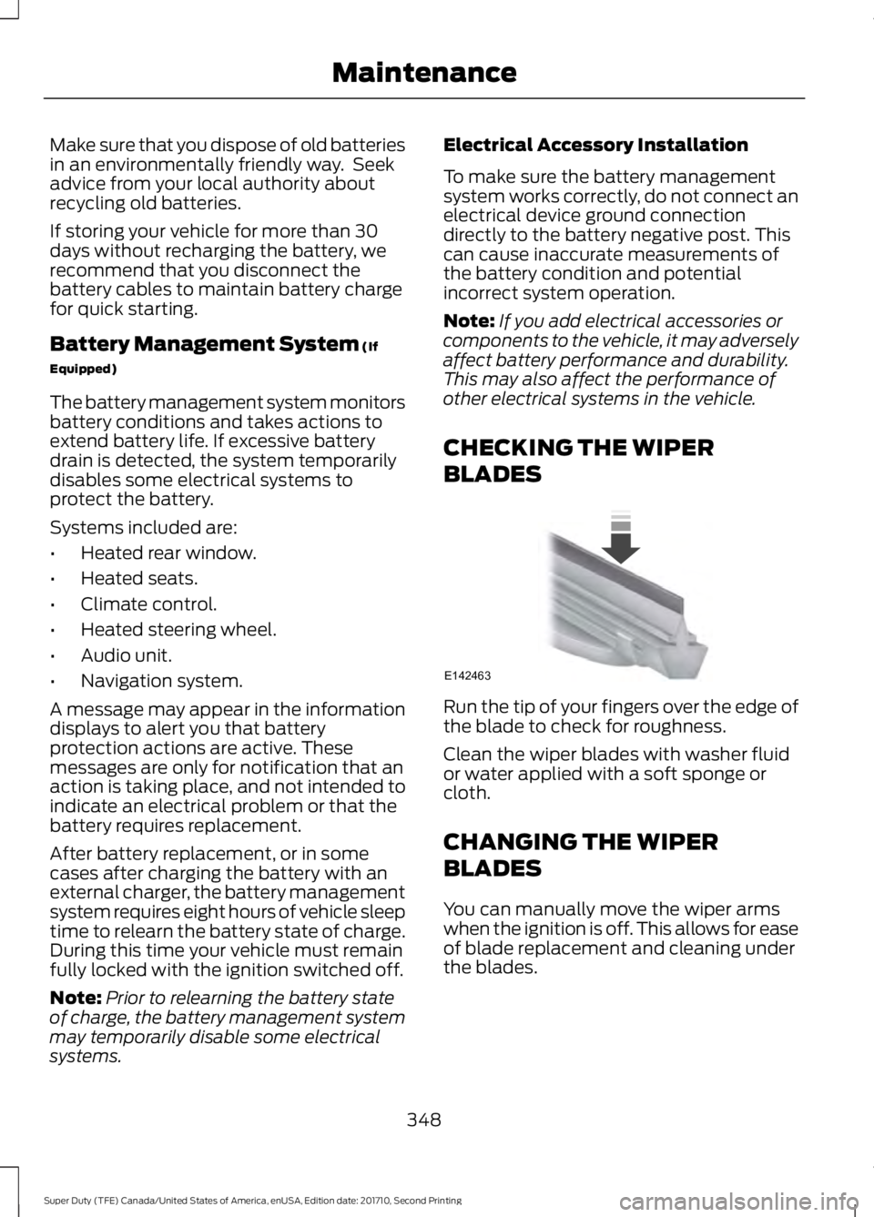
Run the tip of your fingers over the edge ofthe blade to check for roughness.
Clean the wiper blades with washer fluidor water applied with a soft sponge orcloth.
CHANGING THE WIPER
BLADES
You can manually move the wiper armswhen the ignition is off. This allows for easeof blade replacement and cleaning underthe blades.
348
Super Duty (TFE) Canada/United States of America, enUSA, Edition date: 201710, Second Printing
MaintenanceE142463
Page 352 of 642
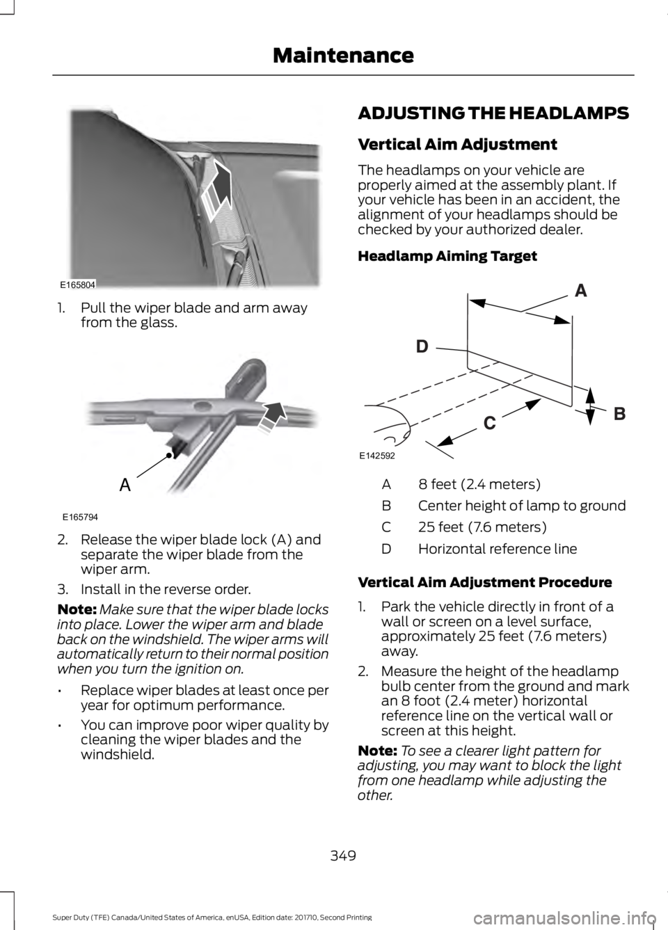
1. Pull the wiper blade and arm awayfrom the glass.
2. Release the wiper blade lock (A) andseparate the wiper blade from thewiper arm.
3. Install in the reverse order.
Note:Make sure that the wiper blade locksinto place. Lower the wiper arm and bladeback on the windshield. The wiper arms willautomatically return to their normal positionwhen you turn the ignition on.
•Replace wiper blades at least once peryear for optimum performance.
•You can improve poor wiper quality bycleaning the wiper blades and thewindshield.
ADJUSTING THE HEADLAMPS
Vertical Aim Adjustment
The headlamps on your vehicle areproperly aimed at the assembly plant. Ifyour vehicle has been in an accident, thealignment of your headlamps should bechecked by your authorized dealer.
Headlamp Aiming Target
8 feet (2.4 meters)A
Center height of lamp to groundB
25 feet (7.6 meters)C
Horizontal reference lineD
Vertical Aim Adjustment Procedure
1. Park the vehicle directly in front of awall or screen on a level surface,approximately 25 feet (7.6 meters)away.
2. Measure the height of the headlampbulb center from the ground and markan 8 foot (2.4 meter) horizontalreference line on the vertical wall orscreen at this height.
Note:To see a clearer light pattern foradjusting, you may want to block the lightfrom one headlamp while adjusting theother.
349
Super Duty (TFE) Canada/United States of America, enUSA, Edition date: 201710, Second Printing
MaintenanceE165804 A
E165794 E142592
Page 353 of 642
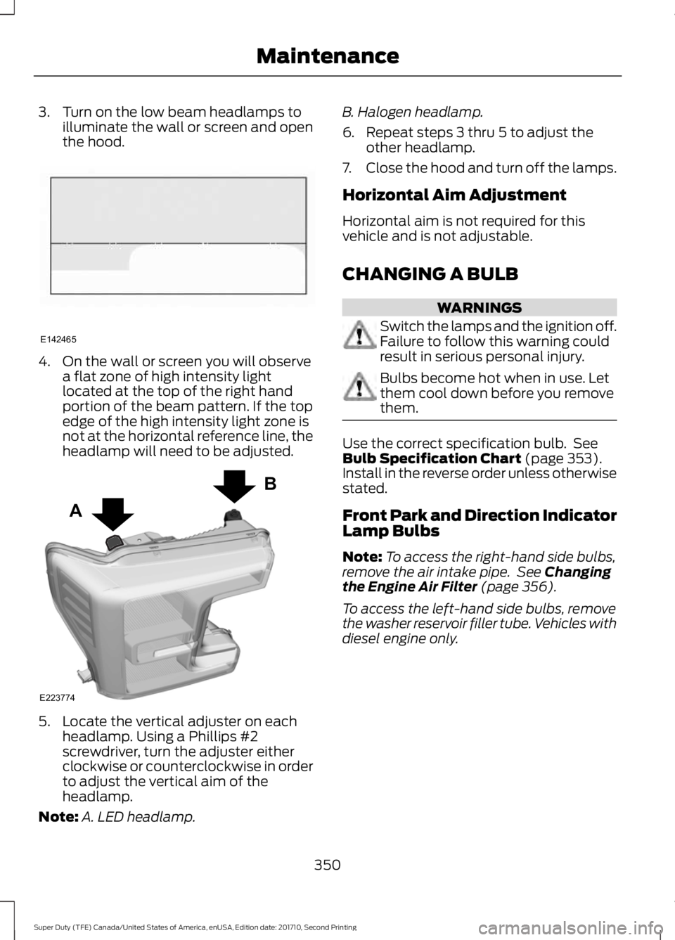
3. Turn on the low beam headlamps toilluminate the wall or screen and openthe hood.
4. On the wall or screen you will observea flat zone of high intensity lightlocated at the top of the right handportion of the beam pattern. If the topedge of the high intensity light zone isnot at the horizontal reference line, theheadlamp will need to be adjusted.
5. Locate the vertical adjuster on eachheadlamp. Using a Phillips #2screwdriver, turn the adjuster eitherclockwise or counterclockwise in orderto adjust the vertical aim of theheadlamp.
Note:A. LED headlamp.
B. Halogen headlamp.
6. Repeat steps 3 thru 5 to adjust theother headlamp.
7.Close the hood and turn off the lamps.
Horizontal Aim Adjustment
Horizontal aim is not required for thisvehicle and is not adjustable.
CHANGING A BULB
WARNINGS
Switch the lamps and the ignition off.Failure to follow this warning couldresult in serious personal injury.
Bulbs become hot when in use. Letthem cool down before you removethem.
Use the correct specification bulb. SeeBulb Specification Chart (page 353).Install in the reverse order unless otherwisestated.
Front Park and Direction IndicatorLamp Bulbs
Note:To access the right-hand side bulbs,remove the air intake pipe. See Changingthe Engine Air Filter (page 356).
To access the left-hand side bulbs, removethe washer reservoir filler tube. Vehicles withdiesel engine only.
350
Super Duty (TFE) Canada/United States of America, enUSA, Edition date: 201710, Second Printing
MaintenanceE142465 A
B
E223774
Page 354 of 642
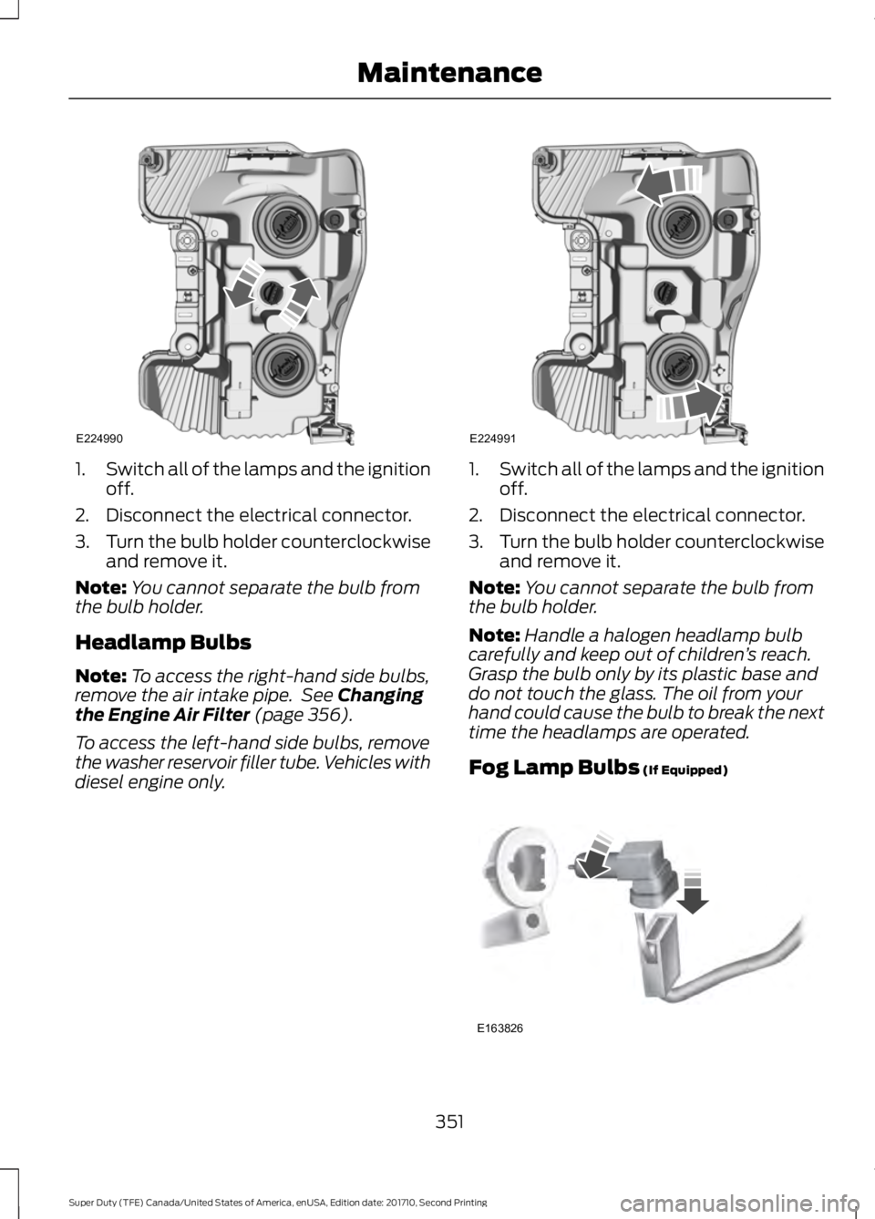
1.Switch all of the lamps and the ignitionoff.
2. Disconnect the electrical connector.
3.Turn the bulb holder counterclockwiseand remove it.
Note:You cannot separate the bulb fromthe bulb holder.
Headlamp Bulbs
Note:To access the right-hand side bulbs,remove the air intake pipe. See Changingthe Engine Air Filter (page 356).
To access the left-hand side bulbs, removethe washer reservoir filler tube. Vehicles withdiesel engine only.
1.Switch all of the lamps and the ignitionoff.
2. Disconnect the electrical connector.
3.Turn the bulb holder counterclockwiseand remove it.
Note:You cannot separate the bulb fromthe bulb holder.
Note:Handle a halogen headlamp bulbcarefully and keep out of children’s reach.Grasp the bulb only by its plastic base anddo not touch the glass. The oil from yourhand could cause the bulb to break the nexttime the headlamps are operated.
Fog Lamp Bulbs (If Equipped)
351
Super Duty (TFE) Canada/United States of America, enUSA, Edition date: 201710, Second Printing
MaintenanceE224990 E224991 E163826
Page 355 of 642
1.Switch all of the lamps and the ignitionoff.
2. To access the bulb, reach behind thebumper.
3. Disconnect the electrical connector.
4.Turn the bulb holder counterclockwiseand remove it.
Note:You cannot separate the bulb fromthe bulb holder.
Note:Handle a halogen bulb carefully andkeep out of children’s reach. Grasp the bulbonly by its plastic base and do not touch theglass. The oil from your hand could causethe bulb to break the next time the foglamps are operated.
Rear Lamps, Brake Lamps, RearDirection Indicator and ReversingLamp Bulbs
Pickup Models - Vehicles without BlindSpot Information System
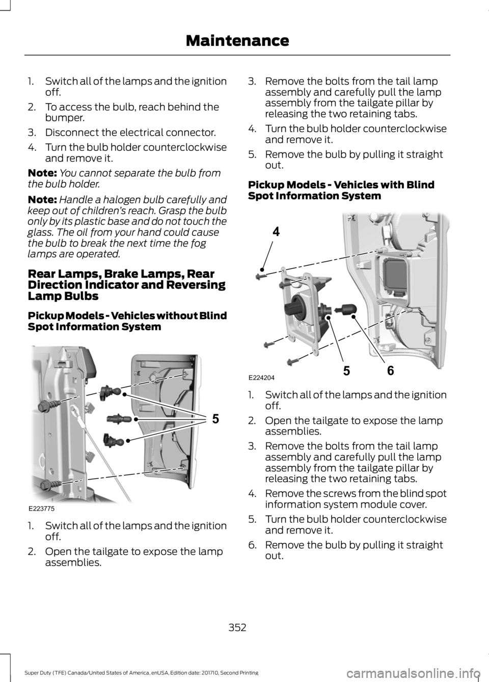
1.Switch all of the lamps and the ignitionoff.
2. Open the tailgate to expose the lampassemblies.
3. Remove the bolts from the tail lampassembly and carefully pull the lampassembly from the tailgate pillar byreleasing the two retaining tabs.
4.Turn the bulb holder counterclockwiseand remove it.
5. Remove the bulb by pulling it straightout.
Pickup Models - Vehicles with BlindSpot Information System
1.Switch all of the lamps and the ignitionoff.
2. Open the tailgate to expose the lampassemblies.
3. Remove the bolts from the tail lampassembly and carefully pull the lampassembly from the tailgate pillar byreleasing the two retaining tabs.
4.Remove the screws from the blind spotinformation system module cover.
5.Turn the bulb holder counterclockwiseand remove it.
6. Remove the bulb by pulling it straightout.
352
Super Duty (TFE) Canada/United States of America, enUSA, Edition date: 201710, Second Printing
MaintenanceE223775
5 E224204
4
65
Page 356 of 642
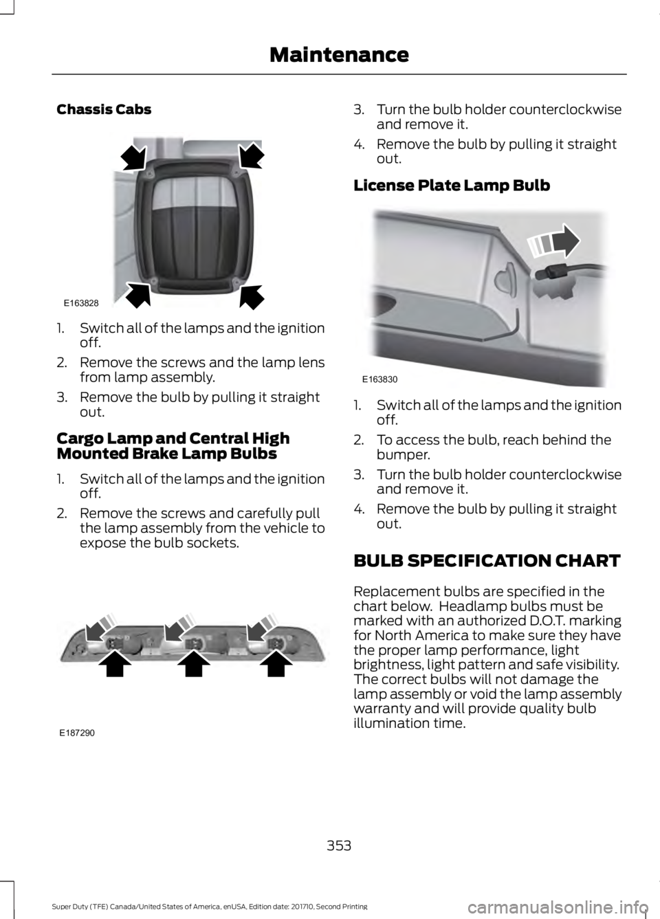
Chassis Cabs
1.Switch all of the lamps and the ignitionoff.
2. Remove the screws and the lamp lensfrom lamp assembly.
3. Remove the bulb by pulling it straightout.
Cargo Lamp and Central HighMounted Brake Lamp Bulbs
1.Switch all of the lamps and the ignitionoff.
2. Remove the screws and carefully pullthe lamp assembly from the vehicle toexpose the bulb sockets.
3.Turn the bulb holder counterclockwiseand remove it.
4. Remove the bulb by pulling it straightout.
License Plate Lamp Bulb
1.Switch all of the lamps and the ignitionoff.
2. To access the bulb, reach behind thebumper.
3.Turn the bulb holder counterclockwiseand remove it.
4. Remove the bulb by pulling it straightout.
BULB SPECIFICATION CHART
Replacement bulbs are specified in thechart below. Headlamp bulbs must bemarked with an authorized D.O.T. markingfor North America to make sure they havethe proper lamp performance, lightbrightness, light pattern and safe visibility.The correct bulbs will not damage thelamp assembly or void the lamp assemblywarranty and will provide quality bulbillumination time.
353
Super Duty (TFE) Canada/United States of America, enUSA, Edition date: 201710, Second Printing
MaintenanceE163828 E187290 E163830
Page 357 of 642
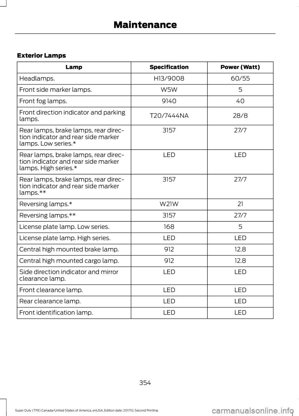
Exterior Lamps
Power (Watt)SpecificationLamp
60/55H13/9008Headlamps.
5W5WFront side marker lamps.
409140Front fog lamps.
28/8T20/7444NAFront direction indicator and parkinglamps.
27/73157Rear lamps, brake lamps, rear direc-tion indicator and rear side markerlamps. Low series.*
LEDLEDRear lamps, brake lamps, rear direc-tion indicator and rear side markerlamps. High series.*
27/73157Rear lamps, brake lamps, rear direc-tion indicator and rear side markerlamps.**
21W21WReversing lamps.*
27/73157Reversing lamps.**
5168License plate lamp. Low series.
LEDLEDLicense plate lamp. High series.
12.8912Central high mounted brake lamp.
12.8912Central high mounted cargo lamp.
LEDLEDSide direction indicator and mirrorclearance lamp.
LEDLEDFront clearance lamp.
LEDLEDRear clearance lamp.
LEDLEDFront identification lamp.
354
Super Duty (TFE) Canada/United States of America, enUSA, Edition date: 201710, Second Printing
Maintenance
Page 358 of 642
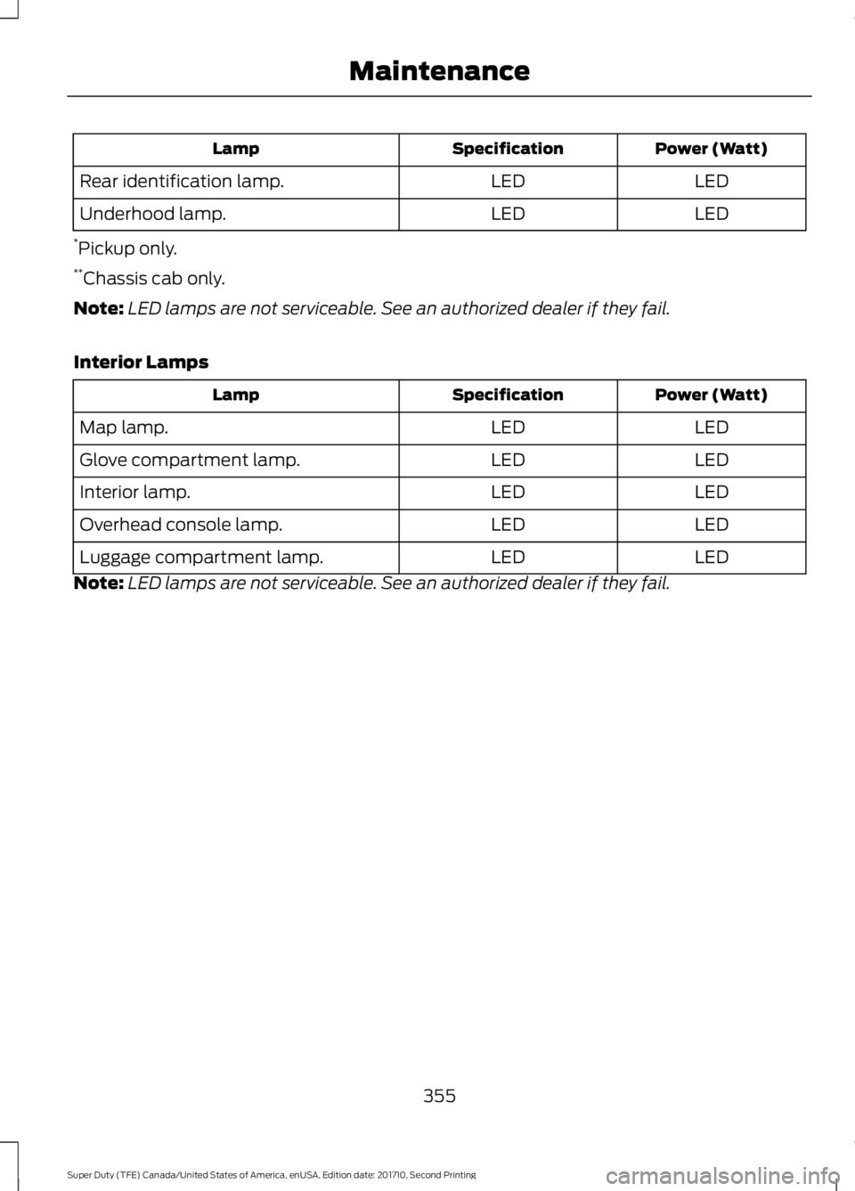
Power (Watt)SpecificationLamp
LEDLEDRear identification lamp.
LEDLEDUnderhood lamp.
*Pickup only.**Chassis cab only.
Note:LED lamps are not serviceable. See an authorized dealer if they fail.
Interior Lamps
Power (Watt)SpecificationLamp
LEDLEDMap lamp.
LEDLEDGlove compartment lamp.
LEDLEDInterior lamp.
LEDLEDOverhead console lamp.
LEDLEDLuggage compartment lamp.
Note:LED lamps are not serviceable. See an authorized dealer if they fail.
355
Super Duty (TFE) Canada/United States of America, enUSA, Edition date: 201710, Second Printing
Maintenance
Page 359 of 642
CHANGING THE ENGINE AIR
FILTER - 6.2L/6.8L
WARNING
To reduce the risk of vehicle damageand personal burn injuries, do notstart your engine with the air cleanerremoved and do not remove it while theengine is running.
Use the correct specification air filterelement. See Motorcraft Parts (page419).
Note: Failure to use the correct air filterelement may result in severe enginedamage. Resulting component damagemay not be covered by the vehicle Warranty.
Change the air filter element at the correctservice interval. See ScheduledMaintenance (page 573).
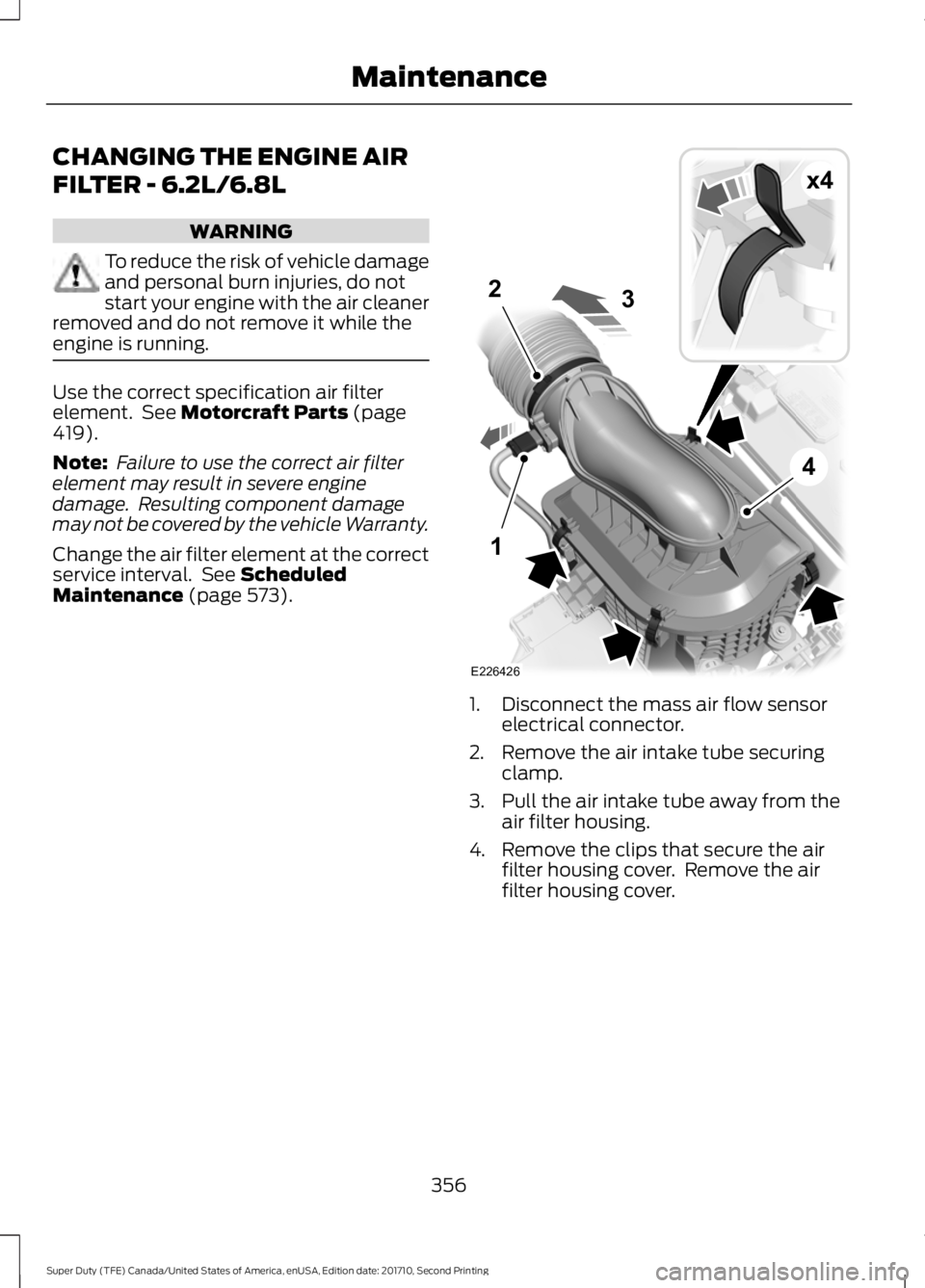
1. Disconnect the mass air flow sensorelectrical connector.
2. Remove the air intake tube securingclamp.
3. Pull the air intake tube away from theair filter housing.
4. Remove the clips that secure the airfilter housing cover. Remove the airfilter housing cover.
356
Super Duty (TFE) Canada/United States of America, enUSA, Edition date: 201710, Second Printing
MaintenanceE226426
x4
1
2
4
3
Page 360 of 642
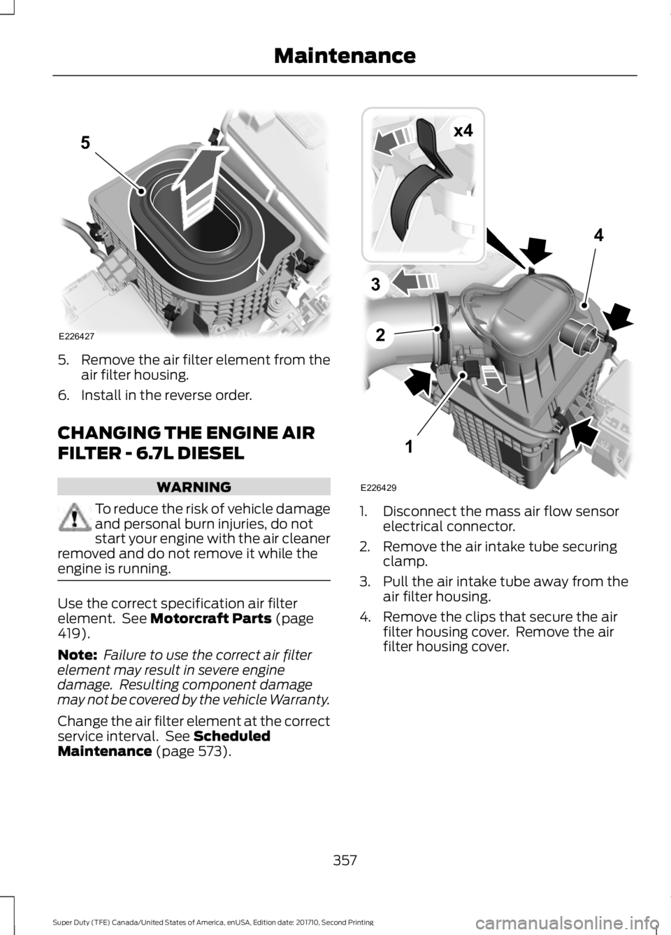
5.Remove the air filter element from theair filter housing.
6. Install in the reverse order.
CHANGING THE ENGINE AIR
FILTER - 6.7L DIESEL
WARNING
To reduce the risk of vehicle damageand personal burn injuries, do notstart your engine with the air cleanerremoved and do not remove it while theengine is running.
Use the correct specification air filterelement. See Motorcraft Parts (page419).
Note: Failure to use the correct air filterelement may result in severe enginedamage. Resulting component damagemay not be covered by the vehicle Warranty.
Change the air filter element at the correctservice interval. See ScheduledMaintenance (page 573).
1. Disconnect the mass air flow sensorelectrical connector.
2. Remove the air intake tube securingclamp.
3. Pull the air intake tube away from theair filter housing.
4. Remove the clips that secure the airfilter housing cover. Remove the airfilter housing cover.
357
Super Duty (TFE) Canada/United States of America, enUSA, Edition date: 201710, Second Printing
MaintenanceE226427
5 1
2
4
3
E226429
x4