check engine FORD FESTIVA 1991 Workshop Manual
[x] Cancel search | Manufacturer: FORD, Model Year: 1991, Model line: FESTIVA, Model: FORD FESTIVA 1991Pages: 454, PDF Size: 9.53 MB
Page 161 of 454
Back To Article
I - SYST EM/COMPONENT T EST S
1991 ENGINE PERFORMANCE Ford Motor Co. - Ford/Mercury System & Com ponent T esting
INTRODUCTION
Before testing separate components or systems, perform procedures in BASIC TESTING article in the ENGINE PERFORMANCE Section.
Since many computer-controlled and monitored components set a trouble code if they malfunction, also perform procedures in TESTS
W/CODES article in the ENGINE PERFORMANCE Section.
AIR INDUCTION SYSTEMS
TURBOCHARGERS
Wastegate Actuator
Disconnect air hose from wastegate actuator. Apply 7.0-8.6 psi (.5-.6 kg/cm2 ) regulated air pressure to wastegate inlet fitting. Replace
turbocharger if wastegate actuator rod does not move.
COMPUTERIZED ENGINE CONTROLS
ELECTRONIC CONTROL ASSEMBLY (ECA)
Ground Circuits
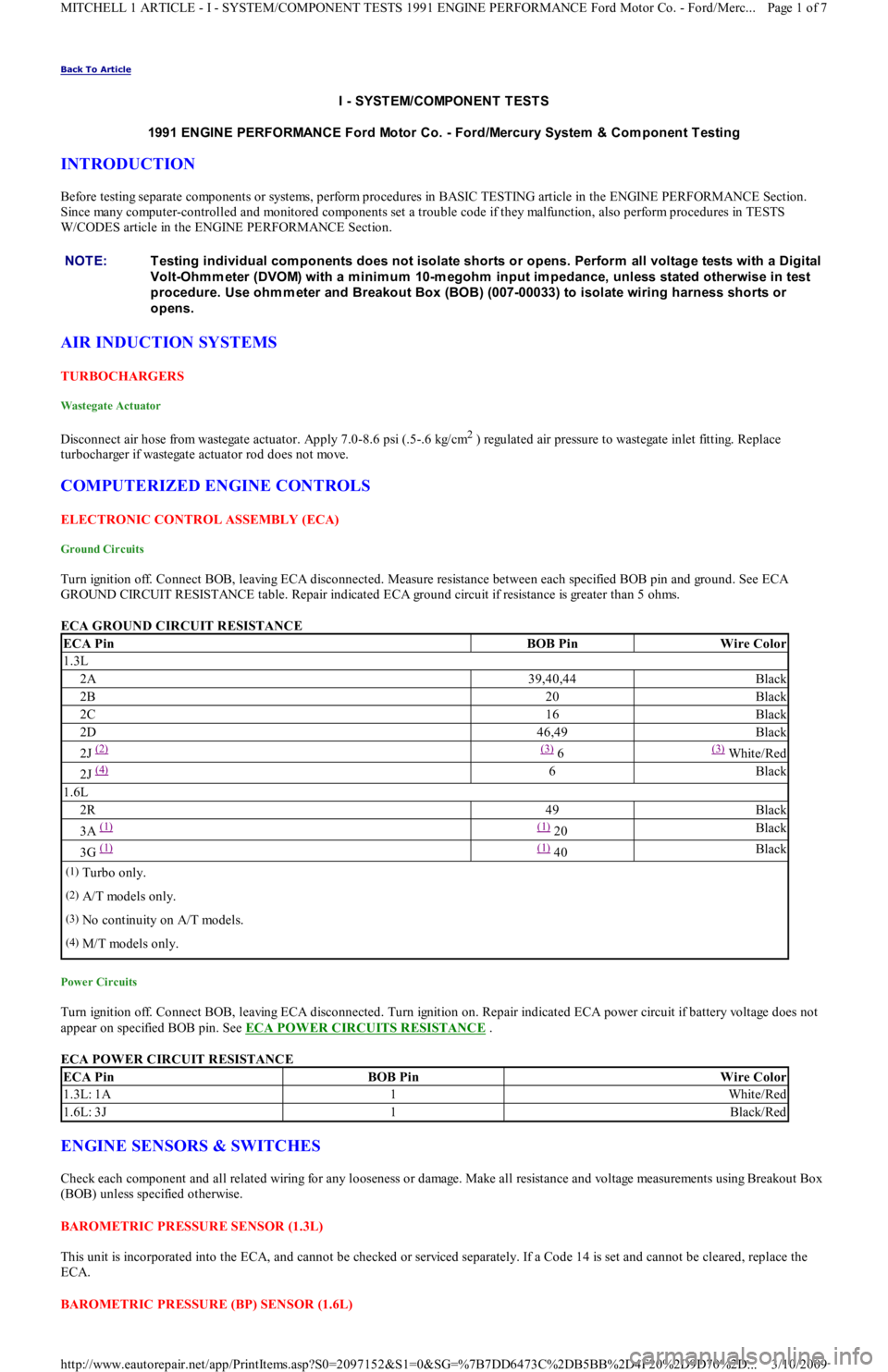
Turn ignition off. Connect BOB, leaving ECA disconnected. Measure resistance between each specified BOB pin and ground. See ECA
GROUND CIRCUIT RESISTANCE table. Repair indicated ECA ground circuit if resistance is greater than 5 ohms.
ECA GROUND CIRCUIT RESISTANCE
Power Circuits
Turn ignition off. Connect BOB, leaving ECA disconnected. Turn ignition on. Repair indicated ECA power circuit if battery voltage d o e s n o t
appear on specified BOB pin. See ECA POWER CIRCUITS RESISTANCE
.
ECA POWER CIRCUIT RESISTANCE
ENGINE SENSORS & SWITCHES
Check each component and all related wiring for any looseness or damage. Make all resistance and voltage measurements using Breakout Box
(BOB) unless specified otherwise.
BAROMETRIC PRESSURE SENSOR (1.3L)
This unit is incorporated into the ECA, and cannot be checked or serviced separately. If a Code 14 is set and cannot be cleared, replace the
ECA.
BAROMETRIC PRESSURE (BP) SENSOR (1.6L) NOTE:T esting individual com ponents does not isolate shorts or opens. Perform all voltage tests with a Digital
Volt-Ohm m eter (DVOM) with a m inim um 10-m egohm input im pedance, unless stated otherwise in test
procedure. Use ohm m eter and Breakout Box (BOB) (007-00033) to isolate wiring harness shorts or
opens.
ECA PinBOB PinWire Color
1.3L
2A39,40,44Black
2B20Black
2C16Black
2D46,49Black
2J (2) (3) 6(3) White/Red
2J (4) 6Black
1.6L
2R49Black
3A (1) (1) 20Black
3G (1) (1) 40Black
(1)Turbo only.
(2)A/T models only.
(3)No continuity on A/T models.
(4)M/T models only.
ECA PinBOB PinWire Color
1.3L: 1A1White/Red
1.6L: 3J1Black/Red
Page 1 of 7 MITCHELL 1 ARTICLE - I - SYSTEM/COMPONENT TESTS 1991 ENGINE PERFORMANCE Ford Motor Co. - Ford/Merc
...
3/10/2009 http://www.eautorepair.net/app/PrintItems.asp?S0=2097152&S1=0&SG=%7B7DD6473C%2DB5BB%2D4F20%2D9D70%2D
...
Page 162 of 454
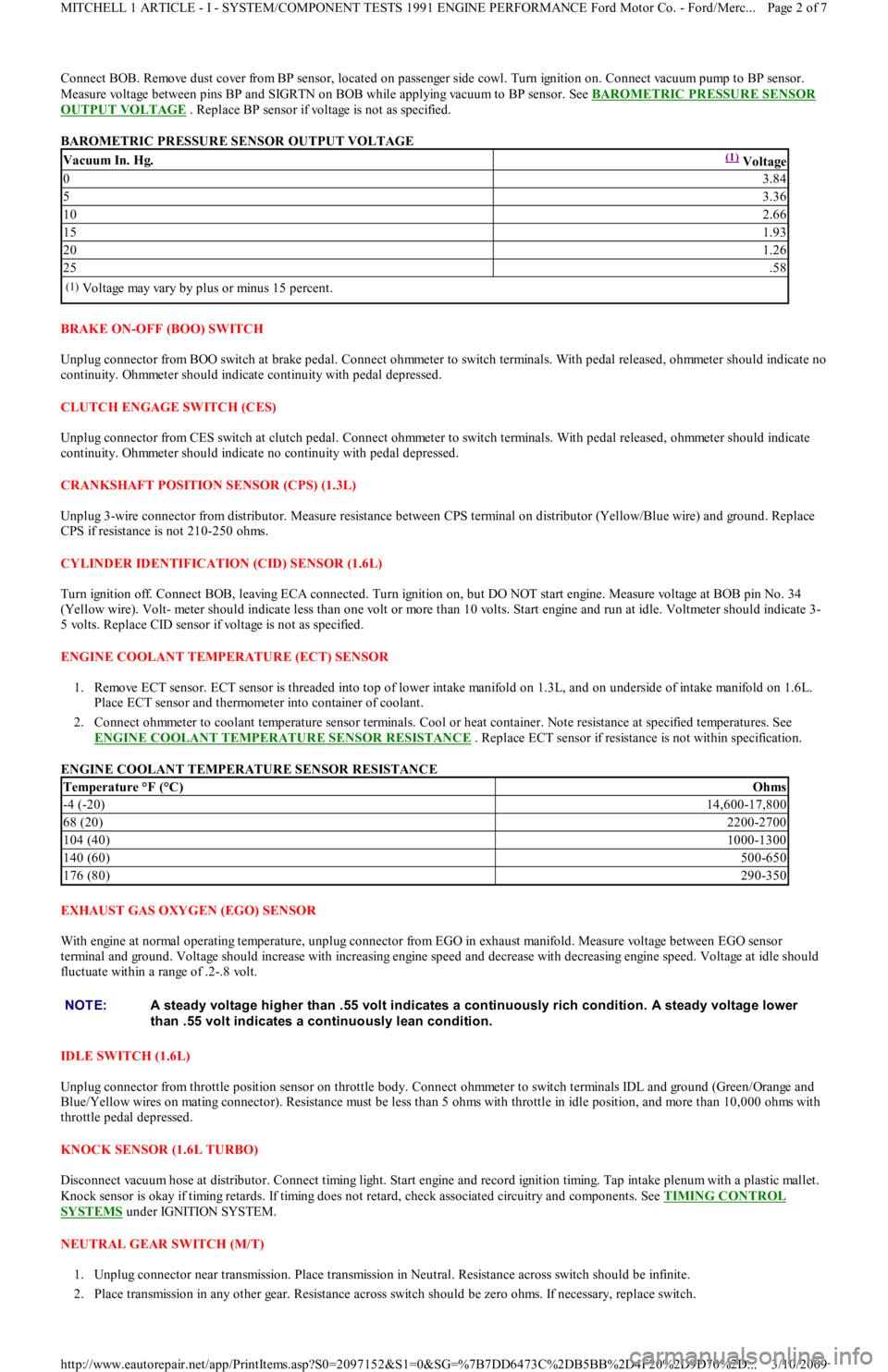
Connect BOB. Remove dust cover from BP sensor, located on passenger side cowl. Turn ignition on. Connect vacuum pump to BP sensor.
Measure voltage between pins BP and SIGRTN on BOB while applying vacuum to BP sensor. See BAROMETRIC PRESSURE SENSOR
OUTPUT VOLTAGE . Replace BP sensor if voltage is not as specified.
BAROMETRIC PRESSURE SENSOR OUTPUT VOLTAGE
BRAKE ON-OFF (BOO) SWITCH
Unplug connector from BOO switch at brake pedal. Connect ohmmeter to switch terminals. With pedal released, ohmmeter should indicate no
continuity. Ohmmeter should indicate continuity with pedal depressed.
CLUTCH ENGAGE SWITCH (CES)
Unplug connector from CES switch at clutch pedal. Connect ohmmeter to switch terminals. With pedal released, ohmmeter should indicate
continuity. Ohmmeter should indicate no continuity with pedal depressed.
CRANKSHAFT POSITION SENSOR (CPS) (1.3L)
Unplug 3-wire connector from distributor. Measure resistance between CPS terminal on distributor (Yellow/Blue wire) and ground. Replace
CPS if resistance is not 210-250 ohms.
CYLINDER IDENTIFICATION (CID) SENSOR (1.6L)
Turn ignition off. Connect BOB, leaving ECA connected. Turn ignition on, but DO NOT start engine. Measure voltage at BOB pin No. 34
(Yellow wire). Volt- meter should indicate less than one volt or more than 10 volts. Start engine and run at idle. Voltmeter should indicate 3-
5 volts. Replace CID sensor if voltage is not as specified.
ENGINE COOLANT TEMPERATURE (ECT) SENSOR
1. Remove ECT sensor. ECT sensor is threaded into top of lower intake manifold on 1.3L, and on underside of intake manifold on 1.6L.
Place ECT sensor and thermometer into container of coolant.
2. Connect ohmmeter to coolant temperature sensor terminals. Cool or heat container. Note resistance at specified temperatures. See
ENGINE COOLANT TEMPERATURE SENSOR RESISTANCE
. Replace ECT sensor if resistance is not within specification.
ENGINE COOLANT TEMPERATURE SENSOR RESISTANCE
EXHAUST GAS OXYGEN (EGO) SENSOR
With engine at normal operating temperature, unplug connector from EGO in exhaust manifold. Measure voltage between EGO sensor
terminal and ground. Voltage should increase with increasing engine speed and decrease with decreasing engine speed. Voltage at idle should
fluctuate within a range of .2-.8 volt.
IDLE SW ITCH (1.6L)
Unplug connector from throttle position sensor on throttle body. Connect ohmmeter to switch terminals IDL and ground (Green/Orange and
Blue/Yellow wires on mating connector). Resistance must be less than 5 ohms with throttle in idle position, and more than 10,000 ohms with
throttle pedal depressed.
KNOCK SENSOR (1.6L TURBO)
Disconnect vacuum hose at distributor. Connect timing light. Start engine and record ignition timing. Tap intake plenum with a plastic mallet.
Knock sensor is okay if timing retards. If timing does not retard, check associated circuitry and components. See TIMING CONTROL
SYSTEMS under IGNITION SYSTEM.
NEUTRAL GEAR SWITCH (M/T)
1. Unplug connector near transmission. Place transmission in Neutral. Resistance across switch should be infinite.
2. Place transmission in any other gear. Resistance across switch should be zero ohms. If necessary, replace switch.
Vacuum In. Hg.(1) Voltage
03.84
53.36
102.66
151.93
201.26
25.58
(1)Voltage may vary by plus or minus 15 percent.
Temperature °F (°C)Ohms
-4 (-20)14,600-17,800
68 (20)2200-2700
104 (40)1000-1300
140 (60)500-650
176 (80)290-350
NOTE:A steady voltage higher than .55 volt indicates a continuously rich condition. A steady voltage lower
than .55 volt indicates a continuously lean condition.
Page 2 of 7 MITCHELL 1 ARTICLE - I - SYSTEM/COMPONENT TESTS 1991 ENGINE PERFORMANCE Ford Motor Co. - Ford/Merc
...
3/10/2009 http://www.eautorepair.net/app/PrintItems.asp?S0=2097152&S1=0&SG=%7B7DD6473C%2DB5BB%2D4F20%2D9D70%2D
...
Page 163 of 454
POWER STEERING PRESSURE SWITCH
1. Start engine and run it at idle. Remove connector from switch. Connect ohmmeter to switch terminals. Turn steering wheel from side to
side while observing ohmmeter.
2. Replace power steering switch if continuity does not exist with front wheels turned, or if continuity exists with wheels straight ahead.
THROTTLE POSITION SENSOR (1.6L)
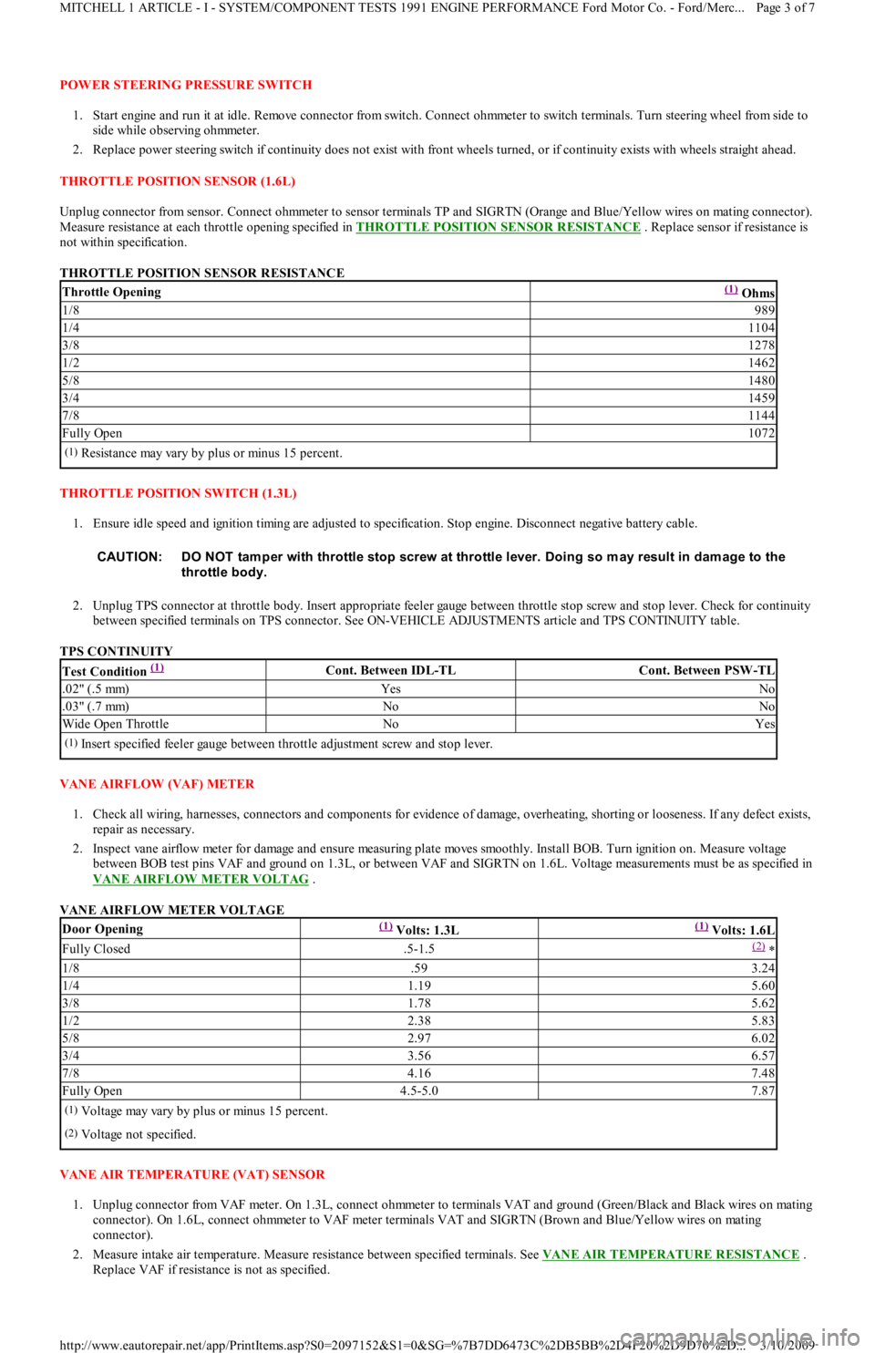
Unplug connector from sensor. Connect ohmmeter to sensor terminals TP and SIGRTN (Orange and Blue/Yellow wires on mating connector).
Measure resistance at each throttle opening specified in THROTTLE POSITION SENSOR RESISTANCE
. Replace sensor if resistance is
not within specification.
THROTTLE POSITION SENSOR RESISTANCE
THROTTLE POSITION SWITCH (1.3L)
1. Ensure idle speed and ignition timing are adjusted to specification. Stop engine. Disconnect negative battery cable.
2. Unplug TPS connector at throttle body. Insert appropriate feeler gauge between throttle stop screw and stop lever. Check for continuity
between specified terminals on TPS connector. See ON-VEHICLE ADJUSTMENTS article and TPS CONTINUITY table.
TPS CONTINUITY
VANE AIRFLOW (VAF) METER
1. Check all wiring, harnesses, connectors and components for evidence of damage, overheating, shorting or looseness. If any defect exists,
repair as necessary.
2. Inspect vane airflow meter for damage and ensure measuring plate moves smoothly. Install BOB. Turn ignition on. Measure voltage
between BOB test pins VAF and ground on 1.3L, or between VAF and SIGRTN on 1.6L. Voltage measurements must be as specified in
VANE AIRFLOW METER VOLTAG
.
VANE AIRFLOW METER VOLTAGE
VANE AIR TEMPERATURE (VAT) SENSOR
1. Unplug connector from VAF meter. On 1.3L, connect ohmmeter to terminals VAT and ground (Green/Black and Black wires on mating
connector). On 1.6L, connect ohmmeter to VAF meter terminals VAT and SIGRTN (Brown and Blue/Yellow wires on mating
connector).
2. Measure intake air temperature. Measure resistance between specified terminals. See VANE AIR TEMPERATURE RESISTANCE
.
Replace VAF if resistance is not as specified.
Throttle Opening(1) Ohms
1/8989
1/41104
3/81278
1/21462
5/81480
3/41459
7/81144
Fully Open1072
(1)Resistance may vary by plus or minus 15 percent.
CAUT ION: DO NOT tam per with throttle stop screw at throttle lever. Doing so m ay result in dam age to the
throttle body.
Test Condition (1) Cont. Between IDL-TLCont. Between PSW-TL
.02" (.5 mm)YesNo
.03" (.7 mm)NoNo
Wide Open ThrottleNoYes
(1)Insert specified feeler gauge between throttle adjustment screw and stop lever.
Door Opening(1) Volts: 1.3L(1) Volts: 1.6L
Fully Closed.5-1.5(2) *
1/8.593.24
1/41.195.60
3/81.785.62
1/22.385.83
5/82.976.02
3/43.566.57
7/84.167.48
Fully Open4.5-5.07.87
(1)Voltage may vary by plus or minus 15 percent.
(2)Voltage not specified.
Page 3 of 7 MITCHELL 1 ARTICLE - I - SYSTEM/COMPONENT TESTS 1991 ENGINE PERFORMANCE Ford Motor Co. - Ford/Merc
...
3/10/2009 http://www.eautorepair.net/app/PrintItems.asp?S0=2097152&S1=0&SG=%7B7DD6473C%2DB5BB%2D4F20%2D9D70%2D
...
Page 164 of 454
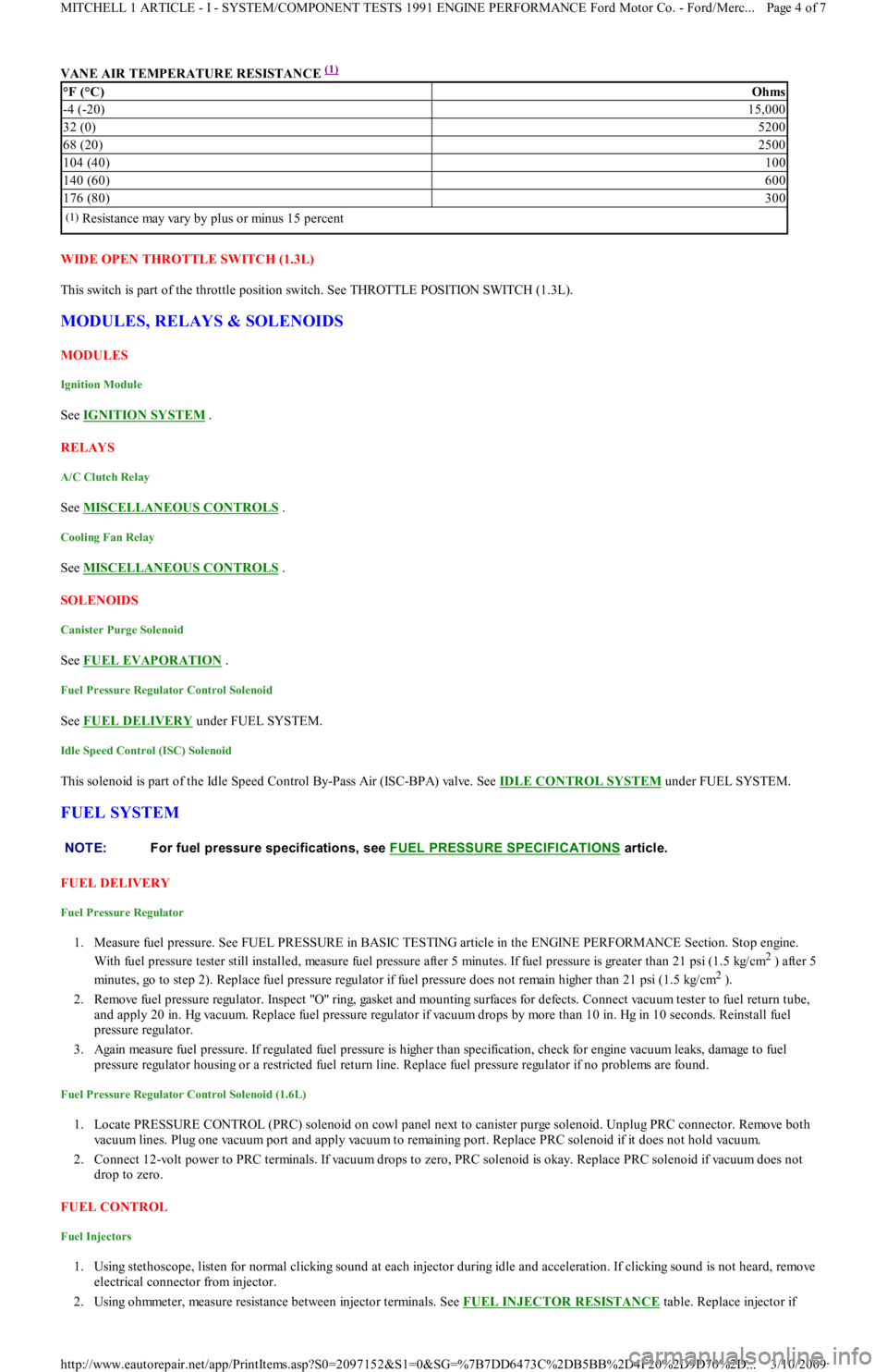
VANE AIR TEMPERATURE RESISTANCE (1)
WIDE OPEN THROTTLE SWITCH (1.3L)
This switch is part of the throttle position switch. See THROTTLE POSITION SWITCH (1.3L).
MODULES, RELAYS & SOLENOIDS
MODULES
Ignition Module
See IGNITION SYSTEM .
RELAYS
A/C Clutch Relay
See MISCELLANEOUS CONTROLS .
Cooling Fan Relay
See MISCELLANEOUS CONTROLS .
SOLENOIDS
Canister Purge Solenoid
See FUEL EVAPORATION .
Fuel Pressure Regulator Control Solenoid
See FUEL DELIVERY under FUEL SYSTEM.
Idle Speed Control (ISC) Solenoid
This solenoid is part of the Idle Speed Control By-Pass Air (ISC-BPA) valve. See IDLE CONTROL SYSTEM under FUEL SYSTEM.
FUEL SYSTEM
FUEL DELIVERY
Fuel Pressure Regulator
1. Measure fuel pressure. See FUEL PRESSURE in BASIC TESTING article in the ENGINE PERFORMANCE Section. Stop engine.
With fuel pressure tester still installed, measure fuel pressure after 5 minutes. If fuel pressure is greater than 21 psi (1.5 kg/cm
2 ) after 5
minutes, go to step 2). Replace fuel pressure regulator if fuel pressure does not remain higher than 21 psi (1.5 kg/cm
2 ).
2. Remove fuel pressure regulator. Inspect "O" ring, gasket and mounting surfaces for defects. Connect vacuum tester to fuel return tube,
and apply 20 in. Hg vacuum. Replace fuel pressure regulator if vacuum drops by more than 10 in. Hg in 10 seconds. Reinstall fuel
pressure regulator.
3. Again measure fuel pressure. If regulated fuel pressure is higher than specification, check for engine vacuum leaks, damage to fuel
pressure regulator housing or a restricted fuel return line. Replace fuel pressure regulator if no problems are found.
Fuel Pressure Regulator Control Solenoid (1.6L)
1. Locate PRESSURE CONTROL (PRC) solenoid on cowl panel next to canister purge solenoid. Unplug PRC connector. Remove both
vacuum lines. Plug one vacuum port and apply vacuum to remaining port. Replace PRC solenoid if it does not hold vacuum.
2. Connect 12-volt power to PRC terminals. If vacuum drops to zero, PRC solenoid is okay. Replace PRC solenoid if vacuum does not
drop to zero.
FUEL CONTROL
Fuel Injectors
1. Using stethoscope, listen for normal clicking sound at each injector during idle and acceleration. If clicking sound is not heard, remove
electrical connector from injector.
2. Using ohmmeter, measure resistance between injector terminals. See FUEL INJECTOR RESISTANCE
table. Replace injector if
°F (°C)Ohms
-4 (-20)15,000
32 (0)5200
68 (20)2500
104 (40)100
140 (60)600
176 (80)300
(1)Resistance may vary by plus or minus 15 percent
NOTE:For fuel pressure specifications, see FUEL PRESSURE SPECIFICAT IONS
article.
Page 4 of 7 MITCHELL 1 ARTICLE - I - SYSTEM/COMPONENT TESTS 1991 ENGINE PERFORMANCE Ford Motor Co. - Ford/Merc
...
3/10/2009 http://www.eautorepair.net/app/PrintItems.asp?S0=2097152&S1=0&SG=%7B7DD6473C%2DB5BB%2D4F20%2D9D70%2D
...
Page 165 of 454
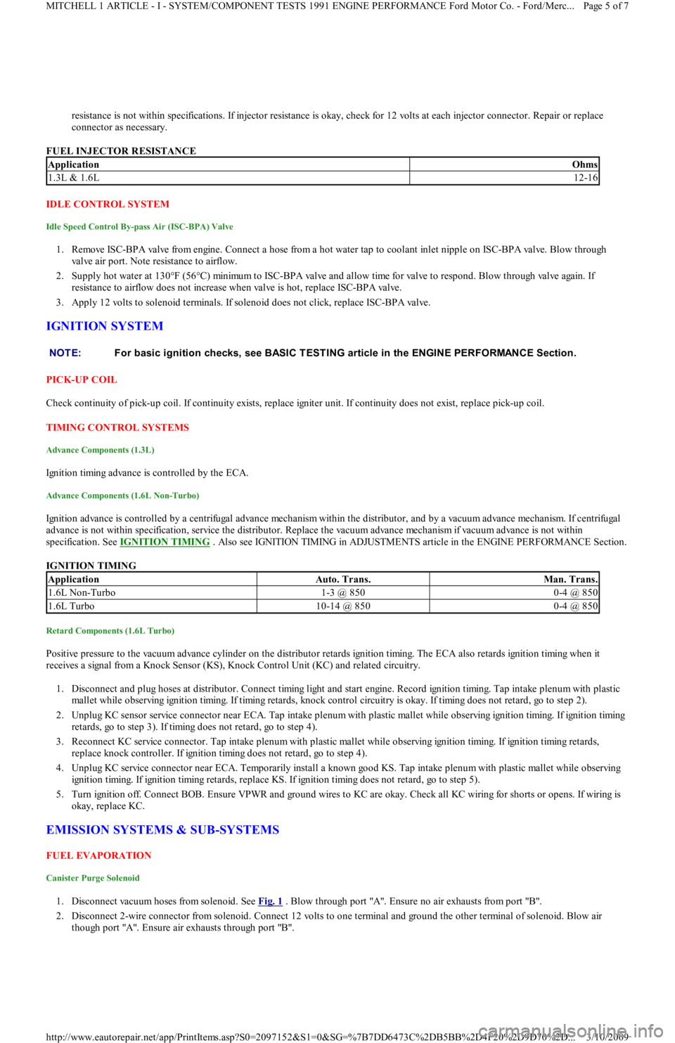
resistance is not within specifications. If injector resistance is okay, check for 12 volts at each injector connector. Repair or replace
connector as necessary.
FUEL INJECTOR RESISTANCE
IDLE CONTROL SYSTEM
Idle Speed Control By-pass Air (ISC-BPA) Valve
1. Remove ISC-BPA valve from engine. Connect a hose from a hot water tap to coolant inlet nipple on ISC-BPA valve. Blow through
valve air port. Note resistance to airflow.
2. Supply hot water at 130°F (56°C) minimum to ISC-BPA valve and allow time for valve to respond. Blow through valve again. If
resistance to airflow does not increase when valve is hot, replace ISC-BPA valve.
3. Apply 12 volts to solenoid terminals. If solenoid does not click, replace ISC-BPA valve.
IGNITION SYSTEM
PICK-UP COIL
Check continuity of pick-up coil. If continuity exists, replace igniter unit. If continuity does not exist, replace pick-up coil.
TIMING CONTROL SYSTEMS
Advance Components (1.3L)
Ignition timing advance is controlled by the ECA.
Advance Components (1.6L Non-Turbo)
Ignition advance is controlled by a centrifugal advance mechanism within the distributor, and by a vacuum advance mechanism. If centrifugal
advance is not within specification, service the distributor. Replace the vacuum advance mechanism if vacuum advance is not within
specification. See IGNITION TIMING
. Also see IGNITION TIMING in ADJUSTMENTS article in the ENGINE PERFORMANCE Section.
IGNITION TIMING
Retard Components (1.6L Turbo)
Positive pressure to the vacuum advance cylinder on the distributor retards ignition timing. The ECA also retards ignition timing when it
receives a signal from a Knock Sensor (KS), Knock Control Unit (KC) and related circuitry.
1. Disconnect and plug hoses at distributor. Connect timing light and start engine. Record ignition timing. Tap intake plenum with plastic
mallet while observing ignition timing. If timing retards, knock control circuitry is okay. If timing does not retard, go to step 2).
2. Unplug KC sensor service connector near ECA. Tap intake plenum with plastic mallet while observing ignition timing. If ignition timing
retards, go to step 3). If timing does not retard, go to step 4).
3. Reconnect KC service connector. Tap intake plenum with plastic mallet while observing ignition timing. If ignition timing retards,
replace knock controller. If ignition timing does not retard, go to step 4).
4. Unplug KC service connector near ECA. Temporarily install a known good KS. Tap intake plenum with plastic mallet while observing
ignition timing. If ignition timing retards, replace KS. If ignition timing does not retard, go to step 5).
5. Turn ignition off. Connect BOB. Ensure VPWR and ground wires to KC are okay. Check all KC wiring for shorts or opens. If wiring is
okay, replace KC.
EMISSION SYSTEMS & SUB-SYSTEMS
FUEL EVAPORATION
Canister Purge Solenoid
1. Disconnect vacuum hoses from solenoid. See Fig. 1 . Blow through port "A". Ensure no air exhausts from port "B".
2. Disconnect 2-wire connector from solenoid. Connect 12 volts to one terminal and ground the other terminal of solenoid. Blow air
though port "A". Ensure air exhausts through port "B".
ApplicationOhms
1.3L & 1.6L12-16
NOTE:For basic ignition checks, see BASIC T EST ING article in the ENGINE PERFORMANCE Section.
ApplicationAuto. Trans.Man. Trans.
1.6L Non-Turbo1-3 @ 8500-4 @ 850
1.6L Turbo10-14 @ 8500-4 @ 850
Page 5 of 7 MITCHELL 1 ARTICLE - I - SYSTEM/COMPONENT TESTS 1991 ENGINE PERFORMANCE Ford Motor Co. - Ford/Merc
...
3/10/2009 http://www.eautorepair.net/app/PrintItems.asp?S0=2097152&S1=0&SG=%7B7DD6473C%2DB5BB%2D4F20%2D9D70%2D
...
Page 168 of 454
Back To Article
G - T EST S W/CODES
1991-92 ENGINE PERFORMANCE Ford Motor Co. Self-Diagnostics
INTRODUCTION
If no faults were found while performing BASIC TESTING , proceed with self-diagnostics. If no fault codes or only pass codes are present
after entering self-diagnostics, proceed to TESTS W/O CODES article in the ENGINE PERFORMANCE Section for diagnosis by symptom
(i.e., ROUGH IDLE, NO START, etc.).
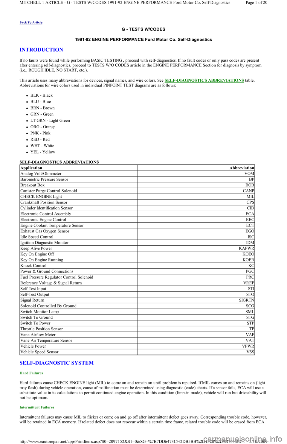
This article uses many abbreviations for devices, signal names, and wire colors. See SELF
-DIAGNOSTICS ABBREVIATIONS table.
Abbreviations for wire colors used in individual PINPOINT TEST diagrams are as follows:
BLK - Black
BLU - Blue
BRN - Brown
GRN - Green
LT GRN - Light Green
ORG - Orange
PNK - Pink
RED - Red
WHT - White
YEL - Yellow
SELF-DIAGNOSTICS ABBREVIATIONS
SELF-DIAGNOSTIC SYSTEM
Hard Failures
Hard failures cause CHECK ENGINE light (MIL) to come on and remain on until problem is repaired. If MIL comes on and remains on (light
may flash) during vehicle operation, cause of malfunction must be determined using diagnostic (code) charts. If a sensor fails, ECA will use a
substitute value in its calculations to permit continued engine operation. In this condition (limp-in mode), vehicle will run but driveability will
not be optimum.
Intermittent Failures
Intermittent failures may cause MIL to flicker or come on and go off after intermittent defect goes away. Corresponding trouble code, however,
will be retained in ECA memory. If related defect does not reoccur within a certain time frame, related trouble code will be erased from ECA
ApplicationAbbreviation
Analog Volt/OhmmeterVOM
Barometric Pressure SensorBP
Breakout BoxBOB
Canister Purge Control SolenoidCANP
CHECK ENGINE LightMIL
Crankshaft Position SensorCPS
Cylinder Identification SensorCID
Electronic Control AssemblyECA
Electronic Engine ControlEEC
Engine Coolant Temperature SensorECT
Exhaust Gas Oxygen SensorEGO
Idle Speed ControlISC
Ignition Diagnostic MonitorIDM
Keep Alive PowerKAPWR
Key On Engine OffKOEO
Key On Engine RunningKOER
Knock ControlKC
Power & Ground ConnectionsPGC
Fuel Pressure Regulator Control SolenoidPRC
Reference Voltage & Signal ReturnVREF
Self-Test InputSTI
Self-Test OutputSTO
Signal ReturnSIGRTN
Solenoid Controlled By GroundSCG
Switch Monitor LampSML
Switch To GroundSTG
Switch To PowerSTP
Throttle Position SensorTP
Vane Airflow MeterVAF
Vane Air Temperature SensorVAT
Vehicle PowerVPWR
Vehicle Speed SensorVSS
Page 1 of 20 MITCHELL 1 ARTICLE - G - TESTS W/CODES 1991-92 ENGINE PERFORMANCE Ford Motor Co. Self-Diagnostics
3/10/2009 http://www.eautorepair.net/app/PrintItems.asp?S0=2097152&S1=0&SG=%7B7DD6473C%2DB5BB%2D4F20%2D9D70%2D
...
Page 169 of 454
memory. Intermittent failures may be caused by a sensor, connector, or wiring. See INTERMITTENTS in TESTS W/O CODES article in the
ENGINE PERFORMANCE Section.
VISUAL CHECK & VEHICLE PREPARATION
Before connecting any equipment to diagnose EEC system, perform following preparatory procedures:
Verify condition of air cleaner and air ducts.
Check all vacuum hoses for leaks, restrictions, or improper routing.
Check EEC system wiring harness electrical connections for corrosion, bent or broken pins, loose wires or terminals, or improper
routing.
Check ECA, sensors, and actuators for physical damage.
Check engine oil and coolant level.
Perform all necessary safety precautions to prevent personal injury or vehicle damage.
Set parking brake. Place shift lever in Park for automatic transmissions, or Neutral for manual transmissions. DO NOT move shift lever
during test unless specifically directed.
Turn off all lights and accessories. Ensure vehicle doors are closed when measuring voltage or resistance.
Start engine. Run at idle until upper radiator hose is hot and pressurized and engine is off fast idle. Check for leaks around exhaust
manifold, exhaust gas oxygen sensor, and vacuum hose connections.
Turn ignition off. Service items as required. Go to EQUIPMENT HOOK-UP .
EQUIPMENT HOOK-UP
VOM
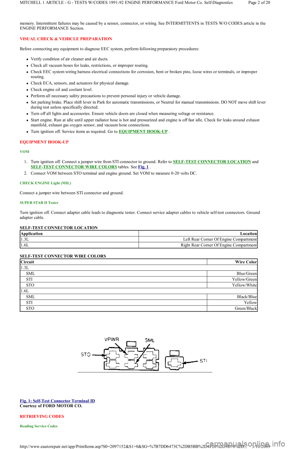
1. Turn ignition off. Connect a jumper wire from STI connector to ground. Refer to SELF-TEST CONNECTOR LOCATION and
SELF
-TEST CONNECTOR WIRE COLORS tables. See Fig. 1 .
2. Connect VOM between STO terminal and engine ground. Set VOM to measure 0-20 volts DC.
CHECK ENGINE Light (MIL)
Connect a jumper wire between STI connector and ground.
SUPER STAR II Tester
Turn ignition off. Connect adapter cable leads to diagnostic tester. Connect service adapter cables to vehicle self-test connectors. Ground
adapter cable.
SELF-TEST CONNECTOR LOCATION
SELF-TEST CONNECTOR WIRE COLORS
Fig. 1: Self
-Test Connector Terminal ID
Courtesy of FORD MOTOR CO.
RETRIEVING CODES
Reading Service Codes
ApplicationLocation
1.3LLeft Rear Corner Of Engine Compartment
1.6LRight Rear Corner Of Engine Compartment
CircuitWire Color
1.3L
SMLBlue/Green
STIYellow/Green
STOYellow/White
1.6L
SMLBlack/Blue
STIYellow
STOGreen/Black
Page 2 of 20 MITCHELL 1 ARTICLE - G - TESTS W/CODES 1991-92 ENGINE PERFORMANCE Ford Motor Co. Self-Diagnostics
3/10/2009 http://www.eautorepair.net/app/PrintItems.asp?S0=2097152&S1=0&SG=%7B7DD6473C%2DB5BB%2D4F20%2D9D70%2D
...
Page 171 of 454
CLEARING CODES
Clearing Codes Procedure
Disconnect negative battery cable. Press brake pedal for 5-10 seconds. Turn off VOM or Super Star II tester. Reconnect battery.
ECA LOCATION
ECA is located on center console behind kick panel on Capri, and under instrument panel on driver side of Festiva.
QUICK TESTS
KEY ON, ENGINE OFF (KOEO) SELF-TEST
KOEO
1. This is a test of electronic engine control system, conducted with power (voltage) applied and engine not running. Activate self-test, and
record all codes displayed.
2. Erase codes, and repeat self-test. Diagnose only codes occurring during repeat self-test. See TROUBLE CODE DEFINITION
table. If
no codes are present, proceed to KEY ON, ENGINE RUNNING (KOER) SELF
-TEST .
KEY ON, ENGINE RUNNING (KOER) SELF-TEST
KOER
1. Deactivate self-test. Start and run engine at 2000 RPM for 2 minutes to warm up EGO sensor. Turn off engine and wait 10 seconds.
2. Restart engine, and activate self-test. Record all service codes displayed. See TROUBLE CODE DEFINITION
table. If no codes are
present, proceed to SWITCH MONITOR TEST
.
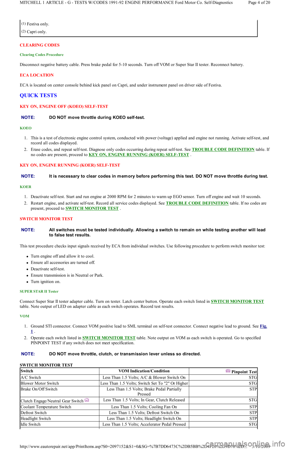
SWITCH MONITOR TEST
This test procedure checks input signals received by ECA from individual switches. Use following procedure to perform switch monitor test:
Turn engine off and allow it to cool.
Ensure all accessories are turned off.
Deactivate self-test.
Ensure transmission is in Neutral or Park.
Turn ignition on.
SUPER STAR II Tester
Connect Super Star II tester adapter cable. Turn on tester. Latch center button. Operate each switch listed in SWITCH MONITOR TEST
table. Note output of LED on adapter cable as each switch operates. Record test results.
VOM
1. Ground STI connector. Connect VOM positive lead to SML terminal on self-test connector. Connect negative lead to ground. See Fig.
1 .
2. Operate each switch listed in SWITCH MONITOR TEST
table. Note output on VOM as each switch is operated. Go to specified
PINPOINT TEST if any switch does not meet specification.
SWITCH MONITOR TEST
(1)Festiva only.
(2)Capri only.
NOTE:DO NOT m ove throttle during KOEO self-test.
NOTE:It is necessary to clear codes in m em ory before perform ing this test. DO NOT m ove throttle during test.
NOTE:All switches m ust be tested individually. Allowing a switch to rem ain on while testing another will lead
to false test results.
NOTE:DO NOT m ove throttle, clutch, or transm ission lever unless so directed.
SwitchVOM Indication/Condition(1) Pinpoint Test
A/C SwitchLess Than 1.5 Volts; A/C & Blower Switch OnSTG
Blower Motor SwitchLess Than 1.5 Volts; Switch Set To "2" Or HigherSTG
Brake On/Off SwitchLess Than 1.5 Volts; Brake Pedal Partially
PressedSTP
Clutch Engage/Neutral Gear Switch (2) Less Than 1.5 Volts; In Gear, Clutch ReleasedSTG
Coolant Temperature SwitchLess Than 1.5 Volts; Cooling Fan OnSTP
Defrost SwitchLess Than 1.5 Volts; Defrost Switch OnSTP
Headlight SwitchLess Than 1.5 Volts; Headlight Switch OnSTP
Id l e Swit chLess Than 1.5 Volts; Accelerator Pedal PressedSTG
Page 4 of 20 MITCHELL 1 ARTICLE - G - TESTS W/CODES 1991-92 ENGINE PERFORMANCE Ford Motor Co. Self-Diagnostics
3/10/2009 http://www.eautorepair.net/app/PrintItems.asp?S0=2097152&S1=0&SG=%7B7DD6473C%2DB5BB%2D4F20%2D9D70%2D
...
Page 172 of 454
WIGGLE TEST
Checking Circuitry
1. Visually inspect suspected sensor, switch, or solenoid. Enter WIGGLE TEST if using Super Star II tester. If using VOM, connect it to
STO terminal on self-test connector, and ground STI self-test connector terminal. Lightly tap sensor, switch, or solenoid.
2. Push and pull on suspected sensor, switch, or solenoid connector, but DO NOT unplug it. Test and wiggle harness vigorously, working
in small sections, from suspected device toward dash panel, and from dash panel to ECA.
3. If VOM or Super Star II tester does not display a positive indication of an intermittent defect, carefully disconnect suspected device.
Remove terminals from connector.
4. Inspect terminals at both ends for corrosion, bad crimps, or improperly seated terminals. Reconnect after inspection. Unplug harness
fro m E CA.
5. Inspect ECA and harness connector terminals for corrosion, bad crimps, or improperly seated terminals. If VOM does not indicate any
intermittent defect, reconnect wiring and erase codes.
PINPOINT TESTS
HOW TO USE PINPOINT TESTS
1. DO NOT perform any PINPOINT TEST unless directed by a QUICK TESTS procedure. Ensure all non-EEC related defects are
corrected. Follow each test step in order until defect is found. DO NOT replace any part unless so directed. When more than one service
code exists, start with first code displayed.
2. PINPOINT TESTS require ensuring electrical circuits are okay before replacing sensors or any other components. Always test circuits
for continuity between sensor and ECA. Test all circuits for shorts to power, opens, or shorts to ground. VREF and VPWR circuits
should be tested with KOEO or as specified in PINPOINT TESTS.
3. DO NOT measure voltage or resistance at ECA, or connect any test light unless specified in testing procedure. DO NOT pierce wiring.
Isolate both ends of a circuit and turn key off whenever checking for shorts or continuity, unless otherwise specified.
4. Disconnect solenoids and switches before checking circuit continuity or energizing solenoids.
5. An open is defined as any resistance greater than 10,000 ohms, unless otherwise specified.
6. To help diagnose circuits to ECA, turn ignition off and disconnect ECA harness. Connect BOB between ECA and ECA harness to
perform circuit and pinpoint tests.
PINPOINT TEST IDM - IGNITION DIAGNOSTIC MONITOR
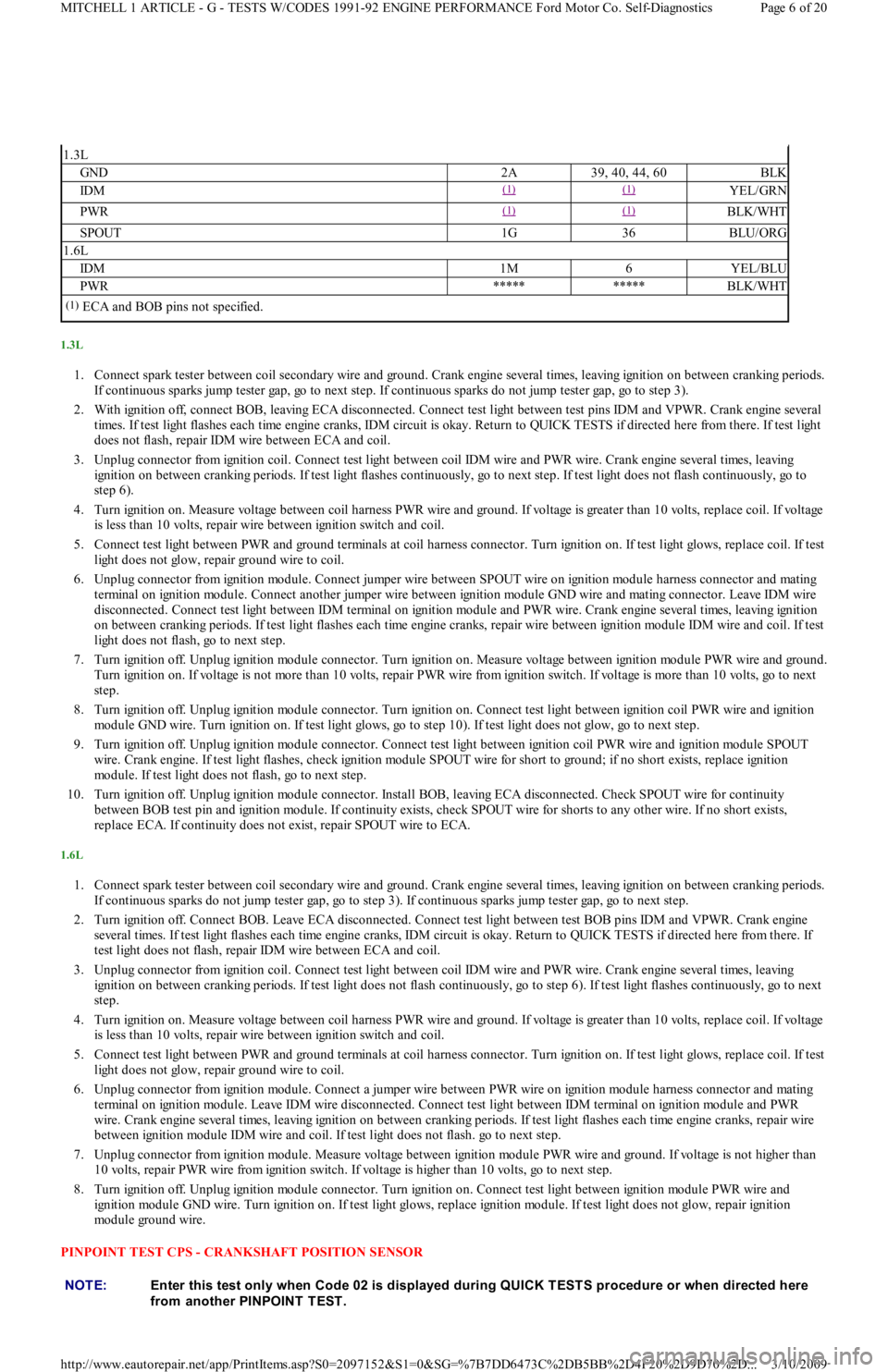
Fig. 3: Identifying IDM Circuit & Connector
IDM CIRCUIT PIN IDENTIFICATION
Manual Lever Position SwitchLess Than 1.5 Volts; Transaxle In Park Or NeutralSTP
Wide Open Throttle SwitchLess Than 1.5 Volts; Accelerator Pedal Fully
PressedSTG
(1)Proceed to PINPOINT TEST indicated if Super Star II tester/VOM indication is incorrect.
(2)Not applicable to vehicles with A/T.
NOTE:Following tests and illustrations are courtesy of Ford Motor Co. Com plete EEC system wiring diagram s
m ay be found in WIRING DIAGRAMS article in the ENGINE PERFORMANCE Section.
NOTE:Check all wiring, harnesses, connectors, and com ponents for dam age, overheating, shorting, or
looseness. If any defect is found, repair as necessary before proceeding to any PINPOINT T EST .
NOTE:Enter this test only when Code 01 is displayed during QUICK T EST S procedure or when directed here
from another PINPOINT TEST.
CircuitECA PinBOB PinWire Color
Page 5 of 20 MITCHELL 1 ARTICLE - G - TESTS W/CODES 1991-92 ENGINE PERFORMANCE Ford Motor Co. Self-Diagnostics
3/10/2009 http://www.eautorepair.net/app/PrintItems.asp?S0=2097152&S1=0&SG=%7B7DD6473C%2DB5BB%2D4F20%2D9D70%2D
...
Page 173 of 454
1.3L
1. Connect spark tester between coil secondary wire and ground. Crank engine several times, leaving ignition on between cranking periods.
If continuous sparks jump tester gap, go to next step. If continuous sparks do not jump tester gap, go to step 3).
2. With ignition off, connect BOB, leaving ECA disconnected. Connect test light between test pins IDM and VPWR. Crank engine several
times. If test light flashes each time engine cranks, IDM circuit is okay. Return to QUICK TESTS if directed here from there. If test light
does not flash, repair IDM wire between ECA and coil.
3. Unplug connector from ignition coil. Connect test light between coil IDM wire and PWR wire. Crank engine several times, leaving
ignition on between cranking periods. If test light flashes continuously, go to next step. If test light does not flash continuously, go to
step 6).
4. Turn ignition on. Measure voltage between coil harness PWR wire and ground. If voltage is greater than 10 volts, replace coil. If voltage
is less than 10 volts, repair wire between ignition switch and coil.
5. Connect test light between PWR and ground terminals at coil harness connector. Turn ignition on. If test light glows, replace coil. If test
light does not glow, repair ground wire to coil.
6. Unplug connector from ignition module. Connect jumper wire between SPOUT wire on ignition module harness connector and mating
terminal on ignition module. Connect another jumper wire between ignition module GND wire and mating connector. Leave IDM wire
disconnected. Connect test light between IDM terminal on ignition module and PWR wire. Crank engine several times, leaving ignition
on between cranking periods. If test light flashes each time engine cranks, repair wire between ignition module IDM wire and coil . If t est
light does not flash, go to next step.
7. Turn ignition off. Unplug ignition module connector. Turn ignition on. Measure voltage between ignition module PWR wire and ground.
Turn ignition on. If voltage is not more than 10 volts, repair PWR wire from ignition switch. If voltage is more than 10 volts, go t o n e xt
step.
8. Turn ignition off. Unplug ignition module connector. Turn ignition on. Connect test light between ignition coil PWR wire and ignition
module GND wire. Turn ignition on. If test light glows, go to step 10). If test light does not glow, go to next step.
9. Turn ignition off. Unplug ignition module connector. Connect test light between ignition coil PWR wire and ignition module SPOUT
wire. Crank engine. If test light flashes, check ignition module SPOUT wire for short to ground; if no short exists, replace ignition
module. If test light does not flash, go to next step.
10. Turn ignition off. Unplug ignition module connector. Install BOB, leaving ECA disconnected. Check SPOUT wire for continuity
between BOB test pin and ignition module. If continuity exists, check SPOUT wire for shorts to any other wire. If no short exists,
replace ECA. If continuity does not exist, repair SPOUT wire to ECA.
1.6L
1. Connect spark tester between coil secondary wire and ground. Crank engine several times, leaving ignition on between cranking periods.
If continuous sparks do not jump tester gap, go to step 3). If continuous sparks jump tester gap, go to next step.
2. Turn ignition off. Connect BOB. Leave ECA disconnected. Connect test light between test BOB pins IDM and VPWR. Crank engine
several times. If test light flashes each time engine cranks, IDM circuit is okay. Return to QUICK TESTS if directed here from there. If
test light does not flash, repair IDM wire between ECA and coil.
3. Unplug connector from ignition coil. Connect test light between coil IDM wire and PWR wire. Crank engine several times, leaving
ignition on between cranking periods. If test light does not flash continuously, go to step 6). If test light flashes continuously, go to next
step.
4. Turn ignition on. Measure voltage between coil harness PWR wire and ground. If voltage is greater than 10 volts, replace coil. If voltage
is less than 10 volts, repair wire between ignition switch and coil.
5. Connect test light between PWR and ground terminals at coil harness connector. Turn ignition on. If test light glows, replace coil. If test
light does not glow, repair ground wire to coil.
6. Unplug connector from ignition module. Connect a jumper wire between PWR wire on ignition module harness connector and mating
terminal on ignition module. Leave IDM wire disconnected. Connect test light between IDM terminal on ignition module and PWR
wire. Crank engine several times, leaving ignition on between cranking periods. If test light flashes each time engine cranks, repair wire
between ignition module IDM wire and coil. If test light does not flash. go to next step.
7. Unplug connector from ignition module. Measure voltage between ignition module PWR wire and ground. If voltage is not higher than
10 volts, repair PWR wire from ignition switch. If voltage is higher than 10 volts, go to next step.
8. Turn ignition off. Unplug ignition module connector. Turn ignition on. Connect test light between ignition module PWR wire and
ignition module GND wire. Turn ignition on. If test light glows, replace ignition module. If test light does not glow, repair ignition
module ground wire.
PINPOINT TEST CPS - CRANKSHAFT POSITION SENSOR
1.3L
GND2A39, 40, 44, 60BLK
IDM(1) (1) YEL/GRN
PWR(1) (1) BLK/WHT
SPOUT1G36BLU/ORG
1.6L
IDM1M6YEL/BLU
PWR**********BLK/WHT
(1)ECA and BOB pins not specified.
NOTE:Enter this test only when Code 02 is displayed during QUICK T EST S procedure or when directed here
from another PINPOINT TEST.
Page 6 of 20 MITCHELL 1 ARTICLE - G - TESTS W/CODES 1991-92 ENGINE PERFORMANCE Ford Motor Co. Self-Diagnostics
3/10/2009 http://www.eautorepair.net/app/PrintItems.asp?S0=2097152&S1=0&SG=%7B7DD6473C%2DB5BB%2D4F20%2D9D70%2D
...