check engine FORD FESTIVA 1991 User Guide
[x] Cancel search | Manufacturer: FORD, Model Year: 1991, Model line: FESTIVA, Model: FORD FESTIVA 1991Pages: 454, PDF Size: 9.53 MB
Page 75 of 454
Back To Article
DRIVE BELT ROUTING
1991-92 ENGINE COOLING BELT ROUT ING
BELT ADJUSTMENT
Tensioners may be used to automatically adjust belt tension to specification. Check belt for fraying. If fraying exists, ensure both belt and
tensioner are properly aligned. See Fig. 1
. Tensioners may contain a belt-wear indicator. See Fig. 2 . If tensioner reaches travel limit, as
indicated by marks on tensioner, replace belt. Ensure serpentine belts are properly installed. See Fig. 3
-Fig. 7 . On models without
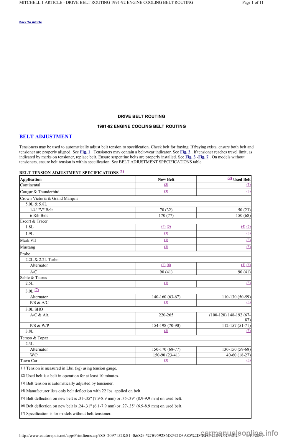
tensioners, ensure belt tension is within specification. See BELT ADJUSTMENT SPECIFICATIONS table.
BELT TENSION ADJUSTMENT SPECIFICATIONS
(1)
ApplicationNew Belt(2) Used Belt
Continental(3) (3)
Cougar & Thunderbird(3) (3)
Crown Victoria & Grand Marquis
5.0L & 5.8L
1/4" "V" Belt70 (32)50 (23)
6 Rib Belt170 (77)150 (68)
Escort & Tracer
1.8L(4) (5) (4) (5)
1.9L(3) (3)
Mark VII(3) (3)
Mustang(3) (3)
Probe
2.2L & 2.2L Turbo
Alternator(4) (6) (4) (6)
A/C90 (41)90 (41)
Sable & Taurus
2.5L(3) (3)
3.0L (7)
Alternator140-160 (63-67)110-130 (50-59)
P/S & A/C(3) (3)
3.0L SHO
A/C & Alt.220-265(100-120) 148-192 (67-
87)
P/S & W/P154-198 (70-90)112-157 (51-71)
3.8L(3) (3)
Tempo & Topaz
2.3L
Alternator150-170 (68-77)130-150 (59-68)
W/P150-90 (23-41)40-60 (18-27)
Town Car(3) (3)
(1)Tension is measured in Lbs. (kg) using tension gauge.
(2)Used belt is a belt in operation for at least 10 minutes.
(3)Belt tension is automatically adjusted by tensioner.
(4)Manufacturer lists only belt deflection with 22 lbs. applied on belt.
(5)Belt deflection on new belt is .31-.35" (7.9-8.9 mm) or .35-.39" (8.9-9.9 mm) on used belt.
(6)Belt deflection on new belt is .24-.31" (6.1-7.9 mm) or .27-.35" (6.9-8.9 mm) on used belt.
(7)Specification is for models without belt tensioner.
Page 1 of 11 MITCHELL 1 ARTICLE - DRIVE BELT ROUTING 1991-92 ENGINE COOLING BELT ROUTING
3/10/2009 http://www.eautorepair.net/app/PrintItems.asp?S0=2097152&S1=0&SG=%7B959286D2%2D3A85%2D4BFC%2D9C5C%2D
...
Page 86 of 454
Back To Article
ENGINE COOLING FAN
1990-92 ENGINE COOLING Ford Motor Co. Engine Cooling Fans
DESCRIPTION
Power for cooling fan is provided by the 20-amp COOLING fuse (Capri) or C-FAN fuse (Festiva). Cooling fan is activated when ground is
supplied for fan motor. On Festiva, ground can be supplied by fuel system ECA (located under the left side of dash), A/C cooling fan relay (if
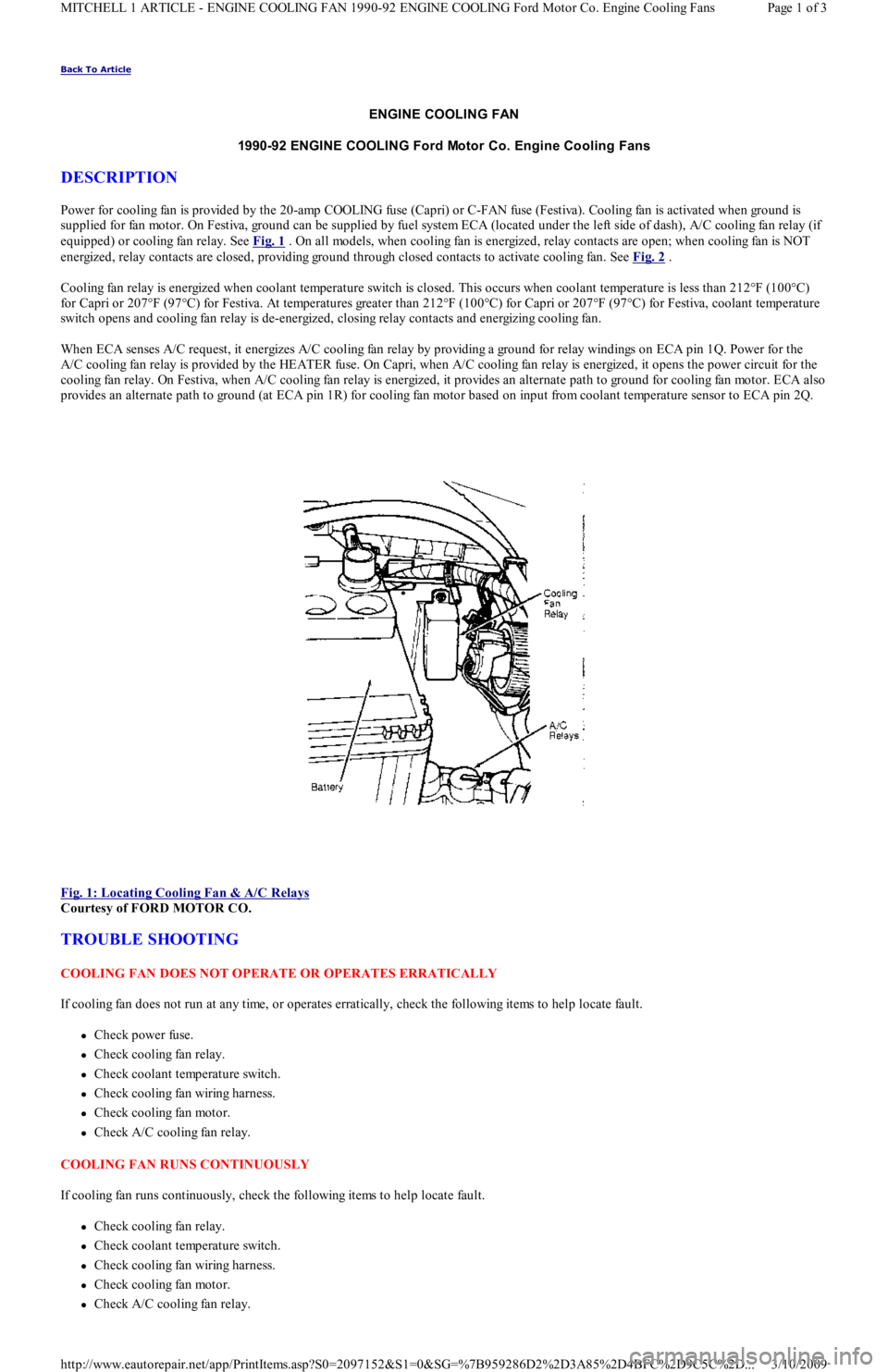
equipped) or cooling fan relay. See Fig. 1
. On all models, when cooling fan is energized, relay contacts are open; when cooling fan is NOT
energized, relay contacts are closed, providing ground through closed contacts to activate cooling fan. See Fig. 2
.
Cooling fan relay is energized when coolant temperature switch is closed. This occurs when coolant temperature is less than 212°F (1 00 °C)
for Capri or 207°F (97°C) for Festiva. At temperatures greater than 212°F (100°C) for Capri or 207°F (97°C) for Festiva, coolant temperature
switch opens and cooling fan relay is de-energized, closing relay contacts and energizing cooling fan.
When ECA senses A/C request, it energizes A/C cooling fan relay by providing a ground for relay windings on ECA pin 1Q. Power for the
A/C cooling fan relay is provided by the HEATER fuse. On Capri, when A/C cooling fan relay is energized, it opens the power circuit for the
cooling fan relay. On Festiva, when A/C cooling fan relay is energized, it provides an alternate path to ground for cooling fan mo t o r. E CA al so
provides an alternate path to ground (at ECA pin 1R) for cooling fan motor based on input from coolant temperature sensor to ECA pin 2Q.
Fig. 1: Locating Cooling Fan & A/C Relays
Courtesy of FORD MOTOR CO.
TROUBLE SHOOTING
COOLING FAN DOES NOT OPERATE OR OPERATES ERRATICALLY
If cooling fan does not run at any time, or operates erratically, check the following items to help locate fault.
Check power fuse.
Check cooling fan relay.
Check coolant temperature switch.
Check cooling fan wiring harness.
Check cooling fan motor.
Check A/C cooling fan relay.
COOLING FAN RUNS CONTINUOUSLY
If cooling fan runs continuously, check the following items to help locate fault.
Check cooling fan relay.
Check coolant temperature switch.
Check cooling fan wiring harness.
Check cooling fan motor.
Check A/C cooling fan relay.
Page 1 of 3 MITCHELL 1 ARTICLE - ENGINE COOLING FAN 1990-92 ENGINE COOLING Ford Motor Co. Engine Cooling Fans
3/10/2009 http://www.eautorepair.net/app/PrintItems.asp?S0=2097152&S1=0&SG=%7B959286D2%2D3A85%2D4BFC%2D9C5C%2D
...
Page 87 of 454
COOLING FAN DOES NOT RUN WITH A/C ON
If cooling fan does not run with A/C on, check the following items to help isolate fault.
Check A/C cooling fan relay.
Check cooling fan wiring harness.
TESTING
VOLTAGE SUPPLY TEST
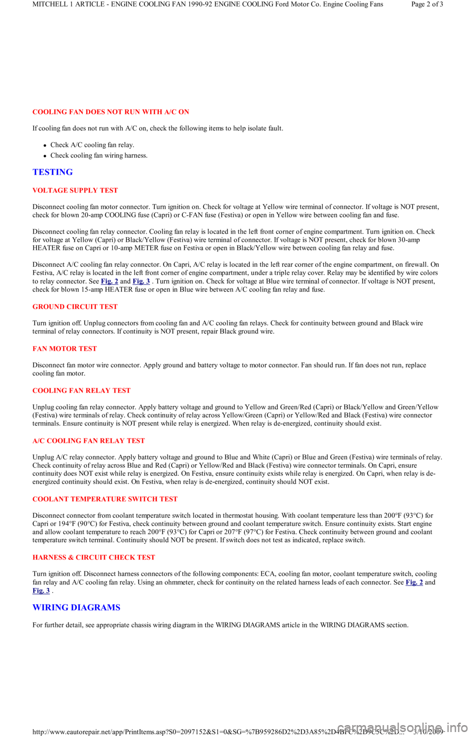
Disconnect cooling fan motor connector. Turn ignition on. Check for voltage at Yellow wire terminal of connector. If voltage is NOT present,
check for blown 20-amp COOLING fuse (Capri) or C-FAN fuse (Festiva) or open in Yellow wire between cooling fan and fuse.
Disconnect cooling fan relay connector. Cooling fan relay is located in the left front corner of engine compartment. Turn ignition on. Check
for voltage at Yellow (Capri) or Black/Yellow (Festiva) wire terminal of connector. If voltage is NOT present, check for blown 30-amp
HEATER fuse on Capri or 10-amp METER fuse on Festiva or open in Black/Yellow wire between cooling fan relay and fuse.
Disconnect A/C cooling fan relay connector. On Capri, A/C relay is located in the left rear corner of the engine compartment, on firewall. On
Festiva, A/C relay is located in the left front corner of engine compartment, under a triple relay cover. Relay may be identified by wire colors
to relay connector. See Fig. 2
and Fig. 3 . Turn ignition on. Check for voltage at Blue wire terminal of connector. If voltage is NOT present,
check for blown 15-amp HEATER fuse or open in Blue wire between A/C cooling fan relay and fuse.
GROUND CIRCUIT TEST
Turn ignition off. Unplug connectors from cooling fan and A/C cooling fan relays. Check for continuity between ground and Black wire
terminal of relay connectors. If continuity is NOT present, repair Black ground wire.
FAN MOTOR TEST
Disconnect fan motor wire connector. Apply ground and battery voltage to motor connector. Fan should run. If fan does not run, replace
cooling fan motor.
COOLING FAN RELAY TEST
Unplug cooling fan relay connector. Apply battery voltage and ground to Yellow and Green/Red (Capri) or Black/Yellow and Green/Yellow
(Festiva) wire terminals of relay. Check continuity of relay across Yellow/Green (Capri) or Yellow/Red and Black (Festiva) wire connector
terminals. Ensure continuity is NOT present while relay is energized. When relay is de-energized, continuity should exist.
A/C COOLING FAN RELAY TEST
Unplug A/C relay connector. Apply battery voltage and ground to Blue and White (Capri) or Blue and Green (Festiva) wire terminals of relay.
Check continuity of relay across Blue and Red (Capri) or Yellow/Red and Black (Festiva) wire connector terminals. On Capri, ensure
continuity does NOT exist while relay is energized. On Festiva, ensure continuity exists while relay is energized. On Capri, when relay is de-
energized continuity should exist. On Festiva, when relay is de-energized, continuity should NOT exist.
COOLANT TEMPERATURE SWITCH TEST
Disconnect connector from coolant temperature switch located in thermostat housing. With coolant temperature less than 200°F (93°C) for
Capri or 194°F (90°C) for Festiva, check continuity between ground and coolant temperature switch. Ensure continuity exists. Start engine
and allow coolant temperature to reach 200°F (93°C) for Capri or 207°F (97°C) for Festiva. Check continuity between ground and coolant
temperature switch terminal. Continuity should NOT be present. If switch does not test as indicated, replace switch.
HARNESS & CIRCUIT CHECK TEST
Turn ignition off. Disconnect harness connectors of the following components: ECA, cooling fan motor, coolant temperature switch, cooling
fan relay and A/C cooling fan relay. Using an ohmmeter, check for continuity on the related harness leads of each connector. See Fig. 2
and
Fig. 3
.
WIRING DIAGRAMS
For further detail, see appropriate chassis wiring diagram in the WIRING DIAGRAMS article in the WIRING DIAGRAMS section.
Page 2 of 3 MITCHELL 1 ARTICLE - ENGINE COOLING FAN 1990-92 ENGINE COOLING Ford Motor Co. Engine Cooling Fans
3/10/2009 http://www.eautorepair.net/app/PrintItems.asp?S0=2097152&S1=0&SG=%7B959286D2%2D3A85%2D4BFC%2D9C5C%2D
...
Page 90 of 454
Back To Article
DRIVE BELT ROUTING
1991-92 ENGINE COOLING BELT ROUT ING
BELT ADJUSTMENT
Tensioners may be used to automatically adjust belt tension to specification. Check belt for fraying. If fraying exists, ensure both belt and
tensioner are properly aligned. See Fig. 1
. Tensioners may contain a belt-wear indicator. See Fig. 2 . If tensioner reaches travel limit, as
indicated by marks on tensioner, replace belt. Ensure serpentine belts are properly installed. See Fig. 3
-Fig. 7 . On models without
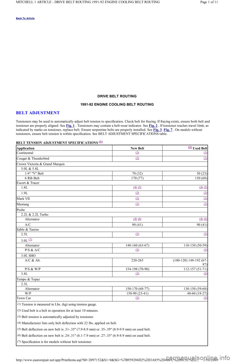
tensioners, ensure belt tension is within specification. See BELT ADJUSTMENT SPECIFICATIONS table.
BELT TENSION ADJUSTMENT SPECIFICATIONS
(1)
ApplicationNew Belt(2) Used Belt
Continental(3) (3)
Cougar & Thunderbird(3) (3)
Crown Victoria & Grand Marquis
5.0L & 5.8L
1/4" "V" Belt70 (32)50 (23)
6 Rib Belt170 (77)150 (68)
Escort & Tracer
1.8L(4) (5) (4) (5)
1.9L(3) (3)
Mark VII(3) (3)
Mustang(3) (3)
Probe
2.2L & 2.2L Turbo
Alternator(4) (6) (4) (6)
A/C90 (41)90 (41)
Sable & Taurus
2.5L(3) (3)
3.0L (7)
Alternator140-160 (63-67)110-130 (50-59)
P/S & A/C(3) (3)
3.0L SHO
A/C & Alt.220-265(100-120) 148-192 (67-
87)
P/S & W/P154-198 (70-90)112-157 (51-71)
3.8L(3) (3)
Tempo & Topaz
2.3L
Alternator150-170 (68-77)130-150 (59-68)
W/P150-90 (23-41)40-60 (18-27)
Town Car(3) (3)
(1)Tension is measured in Lbs. (kg) using tension gauge.
(2)Used belt is a belt in operation for at least 10 minutes.
(3)Belt tension is automatically adjusted by tensioner.
(4)Manufacturer lists only belt deflection with 22 lbs. applied on belt.
(5)Belt deflection on new belt is .31-.35" (7.9-8.9 mm) or .35-.39" (8.9-9.9 mm) on used belt.
(6)Belt deflection on new belt is .24-.31" (6.1-7.9 mm) or .27-.35" (6.9-8.9 mm) on used belt.
(7)Specification is for models without belt tensioner.
Page 1 of 11 MITCHELL 1 ARTICLE - DRIVE BELT ROUTING 1991-92 ENGINE COOLING BELT ROUTING
3/10/2009 http://www.eautorepair.net/app/PrintItems.asp?S0=2097152&S1=0&SG=%7B959286D2%2D3A85%2D4BFC%2D9C5C%2D
...
Page 103 of 454
Disconnect negative battery cable. Drain cooling system. Remove air cleaner. Remove intake manifold bracket. Disconnect throttle cable.
Mark and disconnect vacuum hoses, fuel hoses and wiring. Remove intake manifold bolts. Remove intake manifold and gasket.
Installation (1.3L)
Clean all gasket mating surfaces. Ensure surface is free of burrs, scratches and cracks. Replace all gaskets. Position gasket and manifold to
cylinder head. Install bolts and tighten to specification. To complete installation, reverse removal procedure.
Removal (1.6L)
1. Disconnect negative battery terminal. Relieve fuel pressure. See FUEL PRESSURE RELEASE under REMOVAL &
INSTALLATION. Drain cooling system. Disconnect intercooler tube and/or air intake tube. Disconnect air by-pass hoses. Disconnect
main engine harness electrical connection and TPS connector. Disconnect vacuum hoses from throttle body.
2. Disconnect fuel lines from fuel filter and pressure regulator. Disconnect throttle cable. Disconnect hoses from By-pass Air Control valve
( B AC ) . R e mo ve B AC va l ve r e t a in in g n u t a n d b o l t . R e mo ve in t a ke manifold retaining nuts and bolts from support bracket and cylinder
head. Remove intake manifold and throttle body assembly.
Installation (1.6L)
1. Install new intake manifold gasket, ensuring coolant passage openings align with openings in cylinder head and manifold. Install intake
manifold. Tighten retaining nut and bolts and support bracket bolts to specification. See TORQUE SPECIFICATIONS
table at end of
article.
2. Install BAC valve and connect air hoses. Connect throttle cable. Connect fuel lines to fuel filters and pressure regulator. Connect main
engine harness connector and TPS connector. Connect vacuum lines to throttle body. Install intake air tube. Connect intercooler tube
and/or intake air tube. Connect air by-pass hoses. Fill cooling system. Connect negative battery terminal. Start engine and check for
fluid leaks and correct operation.
EXHAUST MANIFOLD
Removal (1.3L)
1. Raise vehicle. Remove catalytic converter inlet pipe at exhaust manifold. Remove pulse air tube nuts at inlet pipe. Remove inlet pipe
support bracket bolts. Lower vehicle. Remove air intake duct. Remove exhaust manifold heat shroud bolts and remove shroud.
2. Disconnect oxygen sensor connector. Remove exhaust manifold nuts and remove exhaust manifold. Remove gasket from inlet pipe and
cylinder head.
Installation
Position new gasket on cylinder head and inlet pipe. Install exhaust manifold and nuts. Tighten nuts to specification. See, at end of article,
TORQUE SPECIFICATIONS
table. To complete installation, reverse removal procedure. Tighten all bolts and nuts to specification.
Removal (1.6L Non-Turbo)
Remove intake air tube. Remove front exhaust pipe to exhaust manifold retaining nuts. Remove exhaust support bracket (if equipped). Remove
heat shield. Disconnect O2 sensor electrical connector. Remove exhaust manifold.
Installation (1.6L Non-Turbo)
Install exhaust manifold gaskets. Install heavier gasket first. Install exhaust manifold and tighten retaining nuts to specification. See TORQUE
SPECIFICATIONS table at end of article. Connect O2 sensor electrical connector. Install manifold heat shield. Install intake air tube.
Connect front exhaust pipe to intake manifold and tighten retaining nuts to specification. Install exhaust support bracket, if removed, and
tighten engine mount bolt to specification. Start engine and check for leaks.
Removal (1.6L Turbo)
1. Disconnect negative battery cable. Drain cooling system. Remove throttle body air intake tube. Disconnect intercooler hose from
turbocharger assembly and position both intercooler hoses out of the way. Remove O2 sensor connector from its retaining clip, and
disconnect O2 sensor. Remove lower heat shield and then upper heat shield. Remove turbocharger side heat shield.
2. Remove power steering pump (leave hoses attached) and lay aside. Disconnect lower radiator hose from water pump. Position power
steering pump to access mounting bracket retaining bolts and nut. Remove both bolts and one nut, and remove bracket from engine.
Remove 2 screws retaining air cleaner duct tube, loosen clamp at turbocharger and position duct tube out of the way. Disconnect
coolant return hose at turbocharger. Remove bolt and brass sealing washers from oil supply line at engine block.
3. Raise vehicle. Remove retaining nuts and washers from exhaust pipe flange. Remove 2 bolts retaining exhaust hangers to engine block.
Slide off two rubber exhaust hangers at catalytic converter. Pull exhaust pipe downward and to LH side of vehicle. Disconnect oil return
hose at turbocharger. Disconnect coolant return hose at turbocharger. Remove 2 retaining bolts from turbocharger support bracket.
Remove 2 bolts retaining coolant by-pass tube outlet to water pump. Lower vehicle.
4. Loosen retaining clamp bolt on coolant by-pass tube at rear of cylinder head. Remove 11 retaining nuts from exhaust manifold. Pull
coolant by-pass tube bracket from exhaust stud, and position tube out of way. Grasp manifold, pull off studs and move assembly slightly
to RH side of engine compartment to clear cooling fan, and remove assembly from vehicle.
5. Working on bench, remove 4 nuts retaining turbocharger to exhaust manifold, separate assembly and discard gasket.
Installation (1.6L Turbo)
NOTE:Feed O2 sensor wire and guide through upper heat shield.
NOTE:When reinstalling turbocharger, thoroughly rem ove all gaskets and sealant. Use new gaskets. Add .85
oz. (25 cc) of engine oil in the oil passage of the turbocharger.
Page 3 of 19 MITCHELL 1 ARTICLE - ENGINE OVERHAUL 1991-92 FORD MOTOR CO. ENGINES 1.3L & 1.6L 4-Cylinder
3/10/2009 http://www.eautorepair.net/app/PrintItems.asp?S0=2097152&S1=0&SG=%7B959286D2%2D3A85%2D4BFC%2D9C5C%2D
...
Page 104 of 454
1. Position new gasket on exhaust manifold, and install turbocharger onto studs. Install 4 retaining nuts and tighten to specification. See
TORQUE SPECIFICATIONS
table at end of article.
2. Remove oil supply line from turbocharger. Position new (2-piece) exhaust gasket on cylinder head with heavy gasket installed first .
Carefully position turbocharger assembly in engine compartment and slide exhaust manifold on studs. Position heater tube bracket onto
exhaust stud. Install 11 retaining nuts onto exhaust manifold and tighten to specification. See TORQUE SPECIFICATIONS
table at
end of article. Tighten heater tube clamp bolt securely.
3. Raise vehicle. Position new gasket and install 2 retaining bolts on heater tube outlet. Install 2 retaining bolts into turbocharger support
bracket and tighten bolts to specification.
4. Connect coolant return hose. Connect oil return hose and secure with clamp. Position exhaust pipe onto turbocharger, and start nuts
and washers. Install 2 retaining bolts on exhaust hanger at engine. Slide on 2 rubber exhaust hangers at catalytic converter. Tighten
exhaust pipe retaining nuts to specification. Lower vehicle.
5. Install retaining bolt and brass washers on oil supply line, carefully position oil line into vehicle and hand-start bolt into engine block.
Connect and finger tighten oil line to turbocharger. Tighten oil line bolt and oil supply line on turbocharger to specification.
6. Connect coolant supply hose. Position air cleaner duct tube on turbocharger and tighten clamp. Install 2 screws retaining air cleaner
duct tube. Position power steering pump bracket on engine, and install 2 retaining bolts and one retaining nut. Tighten to specification.
Position power steering pump on mounting bracket, and install though bolt and adjuster. Connect lower radiator hose. Install power
steering belt. Position upper heat shield and install 2 retaining bolts finger tight.
7. Position lower heat shield and install three retaining bolts finger tight. Tighten all heat shield bolts to specification. Connect O2 sensor
and install connector into its retaining clip. See TORQUE SPECIFICATIONS
table at end of article. Position intercooler hose on
turbocharger and secure with clamp. Install throttle body air intake tube. Connect negative battery cable. Refill cooling system.
CYLINDER HEAD
Removal (1.3L)
1. Disconnect battery ground cable. Mark and disconnect fuel lines at fuel pump. Remove accessory belts, water pump pulley, crankshaft
pulley, timing belt covers, timing belt tensioner, timing belt, valve cover and exhaust and intake manifolds. Drain cooling system.
2. Mark and remove electrical connectors and vacuum hoses. Remove spark plug wires from spark plugs, and remove spark plugs. Remove
distributor cap. Disconnect vacuum hoses and distributor wiring.
3. Index distributor-to-mount position and remove hold-down bolt. Remove distributor assembly. Remove engine ground strap. Remove
front and rear engine lifting hooks. Remove upper radiator hose, by-pass hose and bracket.
4. Remove bolts retaining rocker arm shaft. Remove rocker arm assemblies. Remove cylinder head bolts. Remove head and gasket.
Inspection (1.3L)
1. Thoroughly clean and check gasket mating surface of cylinder head and block. Check cylinder for cracks, nicks, burrs or damage. Using
a straightedge and feeler gauge, check warpage over entire gasket area. Ensure cylinder head and/or block warpage does not
exceed .006" (.15 mm).
2. If warpage exceeds .006" (.15 mm), machine cylinder head and/or block gasket surface. Maximum machining allowed is .008" (.20 mm).
If more machining is required, replace block and/or cylinder head.
Installation (1.3L)
1. Place new head gasket properly on block. Carefully place cylinder head in position on block. Install head bolts. Tighten bolts in
sequence and in 2 steps. See Fig. 1
.
2. While tightening rocker arm shaft, slide shaft springs away from retaining bolt to prevent pinching springs. Tighten rocker arm shaft bolts
in sequence and to specification. See Fig. 5
. To complete installation, reverse removal procedure. Tighten all bolts/nuts to
specification. Fill all fluids to proper levels. NOTE:T urbocharger-to-exhaust m anifold m ounting nuts are of special quality. Ensure correct nuts are
used.
NOTE:Ensure one brass washer is positioned on each side of oil line fitting.
NOTE:Feed O2 sensor wire through upper heat shield. Install wire retainer under LH bolt.
NOTE:If turbocharger was replaced: Disconnect ignition coil, crank engine for 20 seconds, connect ignition
coil, start engine and run at idle for 30 seconds and check for leaks.
NOTE:If original tim ing belt is being reused, m ark direction of rotation for installation reference.
Page 4 of 19 MITCHELL 1 ARTICLE - ENGINE OVERHAUL 1991-92 FORD MOTOR CO. ENGINES 1.3L & 1.6L 4-Cylinder
3/10/2009 http://www.eautorepair.net/app/PrintItems.asp?S0=2097152&S1=0&SG=%7B959286D2%2D3A85%2D4BFC%2D9C5C%2D
...
Page 106 of 454
article. Install timing belt and covers. Install cam cover. On non-turbo engines, connect front exhaust pipe to exhaust manifold. Tighten
nuts to specification.
4. On turbocharged engines, install exhaust manifold and turbocharger assembly. Install ground wire and strap to cylinder head with
retaining bolts. Connect intercooler tubes (if equipped). Connect O2 sensor connector, and install ground wires to bracket on cylinder
head with retaining screw. Connect main engine harness connector. Connect fuel lines to fuel filter and pressure regulator. Install
throttle cable and retaining brackets.
5. Install coolant hoses and vacuum lines to intake manifold and throttle body. Install coolant hose to thermostat cover. Install intake air
tube to air cleaner. Install spark plug wires and retainers. Install intake air tube to throttle body, and connect by-pass hoses. Fill cooling
system. Connect negative battery terminal. Start engine, check for leaks and system operation.
TIMING BELT COVER
Removal & Installation (1.3L)
Remove accessory belts. Remove water pump pulley. Remove crankshaft damper. Remove bolts retaining upper and lower cover halves to
engine front. Remove both covers. To install, reverse removal procedure.
Removal & Installation (1.6L)
Raise vehicle on hoist. Remove RF tire and wheel assembly. Remove RF splash guard. Lower vehicle. Remove spark plugs and set camsh aft
timing to TDC No. 1 cylinder. Remove oil dipstick. Remove water pump pulley. Remove crankshaft pulley, damper and baffle plate. Remove
upper timing belt cover. Remove center and lower timing belt covers. To install, reverse removal procedure.
TIMING BELT
Removal (1.3L)
Remove accessory belts, water pump pulley, crankshaft damper and upper and lower timing belt covers. Mark timing belt direction of rotation
for installation reference. Remove timing belt tensioner pulley bolt. Remove tensioner pulley, spring and spring cover. Remove timing belt.
Installation (1.3L)
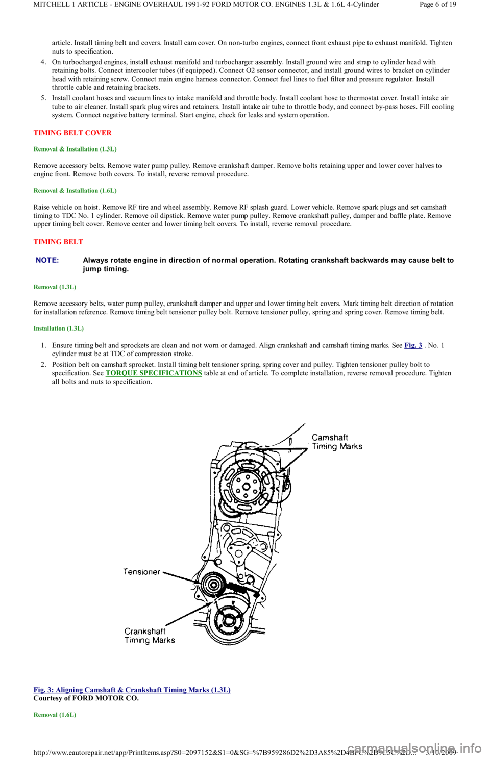
1. Ensure timing belt and sprockets are clean and not worn or damaged. Align crankshaft and camshaft timing marks. See Fig. 3 . No. 1
cylinder must be at TDC of compression stroke.
2. Position belt on camshaft sprocket. Install timing belt tensioner spring, spring cover and pulley. Tighten tensioner pulley bolt to
specification. See TORQUE SPECIFICATIONS
table at end of article. To complete installation, reverse removal procedure. Tighten
all bolts and nuts to specification.
Fig. 3: Aligning Camshaft & Crankshaft Timing Marks (1.3L)
Courtesy of FORD MOTOR CO.
Removal (1.6L)
NOTE:Always rotate engine in direction of norm al operation. Rotating crankshaft backwards m ay cause belt to
jump timing.
Page 6 of 19 MITCHELL 1 ARTICLE - ENGINE OVERHAUL 1991-92 FORD MOTOR CO. ENGINES 1.3L & 1.6L 4-Cylinder
3/10/2009 http://www.eautorepair.net/app/PrintItems.asp?S0=2097152&S1=0&SG=%7B959286D2%2D3A85%2D4BFC%2D9C5C%2D
...
Page 107 of 454
Remove timing belt covers, See TIMING BELT COVER procedure to remove timing belt from this engine.
Installation (1.6L)
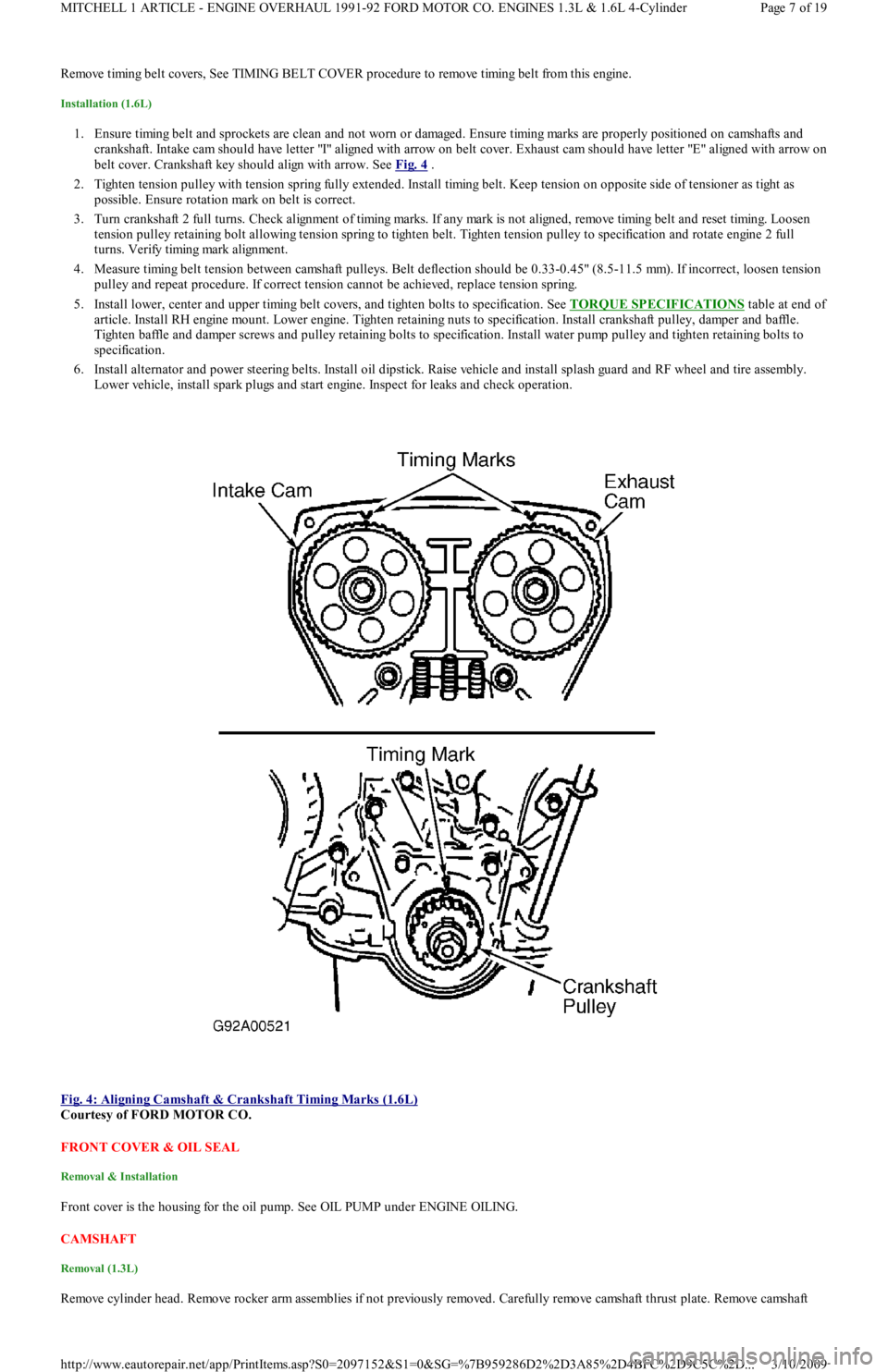
1. Ensure timing belt and sprockets are clean and not worn or damaged. Ensure timing marks are properly positioned on camshafts and
crankshaft. Intake cam should have letter "I" aligned with arrow on belt cover. Exhaust cam should have letter "E" aligned with arrow on
belt cover. Crankshaft key should align with arrow. See Fig. 4
.
2. Tighten tension pulley with tension spring fully extended. Install timing belt. Keep tension on opposite side of tensioner as tight as
possible. Ensure rotation mark on belt is correct.
3. Turn crankshaft 2 full turns. Check alignment of timing marks. If any mark is not aligned, remove timing belt and reset timing. Lo o se n
tension pulley retaining bolt allowing tension spring to tighten belt. Tighten tension pulley to specification and rotate engine 2 full
turns. Verify timing mark alignment.
4. Measure timing belt tension between camshaft pulleys. Belt deflection should be 0.33-0.45" (8.5-11.5 mm). If incorrect, loosen tension
pulley and repeat procedure. If correct tension cannot be achieved, replace tension spring.
5. Install lower, center and upper timing belt covers, and tighten bolts to specification. See TORQUE SPECIFICATIONS
table at end of
article. Install RH engine mount. Lower engine. Tighten retaining nuts to specification. Install crankshaft pulley, damper and baffle.
Tighten baffle and damper screws and pulley retaining bolts to specification. Install water pump pulley and tighten retaining bolts to
specification.
6. Install alternator and power steering belts. Install oil dipstick. Raise vehicle and install splash guard and RF wheel and tire assembly.
Lower vehicle, install spark plugs and start engine. Inspect for leaks and check operation.
Fig. 4: Aligning Camshaft & Crankshaft Timing Marks (1.6L)
Courtesy of FORD MOTOR CO.
FRONT COVER & OIL SEAL
Removal & Installation
Front cover is the housing for the oil pump. See OIL PUMP under ENGINE OILING.
CAMSHAFT
Removal (1.3L)
Remove cylinder head. Remove rocker arm assemblies if not previously removed. Carefully remove camshaft thrust plate. Remove camsh aft
Page 7 of 19 MITCHELL 1 ARTICLE - ENGINE OVERHAUL 1991-92 FORD MOTOR CO. ENGINES 1.3L & 1.6L 4-Cylinder
3/10/2009 http://www.eautorepair.net/app/PrintItems.asp?S0=2097152&S1=0&SG=%7B959286D2%2D3A85%2D4BFC%2D9C5C%2D
...
Page 108 of 454
front oil seal. Carefully slide camshaft out front of cylinder head. DO NOT d a ma ge b e a r in g b o r e s.
Inspection (1.3L)
1. Check cylinder head for warpage. See INSPECTION under CYLINDER HEAD under REMOVAL & INSTALLATION. Measure
camshaft lobes across their maximum dimensions. Inspect for scoring and wear. Replace camshaft if not within specification. See, in this
article, CAMSHAFT LOBE SPECIFICATIONS
table.
2. Measure camshaft bearing journals and cylinder head bores. See Fig. 6
and Fig. 7 . Subtract camshaft bearing journal O.D. from
cylinder head bore I.D. to obtain oil clearance. If clearance is not within specification, replace head and/or camshaft. See, in this article,
CAMSHAFT SPECIFICATIONS
table under ENGINE SPECIFICATIONS tables.
Installation (1.3L)
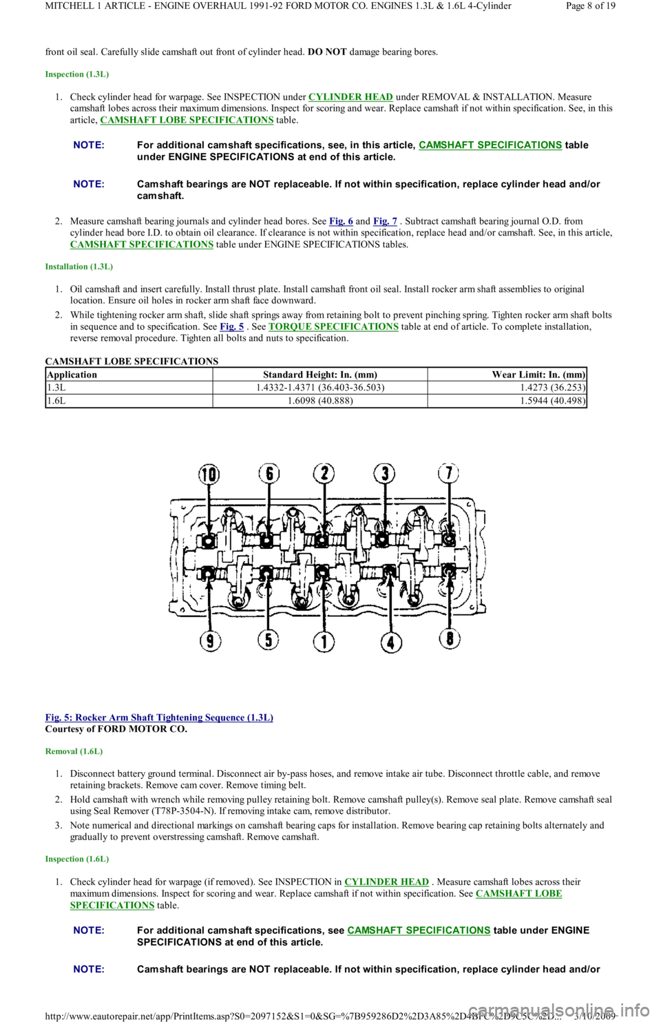
1. Oil camshaft and insert carefully. Install thrust plate. Install camshaft front oil seal. Install rocker arm shaft assemblies to original
location. Ensure oil holes in rocker arm shaft face downward.
2. While tightening rocker arm shaft, slide shaft springs away from retaining bolt to prevent pinching spring. Tighten rocker arm shaft bolts
in sequence and to specification. See Fig. 5
. See TORQUE SPECIFICATIONS table at end of article. To complete installation,
reverse removal procedure. Tighten all bolts and nuts to specification.
CAMSHAFT LOBE SPECIFICATIONS
Fig. 5: Rocker Arm Shaft Tightening Sequence (1.3L)
Courtesy of FORD MOTOR CO.
Removal (1.6L)
1. Disconnect battery ground terminal. Disconnect air by-pass hoses, and remove intake air tube. Disconnect throttle cable, and remove
ret ain in g b racket s. Remo ve cam co ver. Remo ve t imin g b el t .
2. Hold camshaft with wrench while removing pulley retaining bolt. Remove camshaft pulley(s). Remove seal plate. Remove camshaft seal
using Seal Remover (T78P-3504-N). If removing intake cam, remove distributor.
3. Note numerical and directional markings on camshaft bearing caps for installation. Remove bearing cap retaining bolts alternately and
gradually to prevent overstressing camshaft. Remove camshaft.
Inspection (1.6L)
1. Check cylinder head for warpage (if removed). See INSPECTION in CYLINDER HEAD . Measure camshaft lobes across their
maximum dimensions. Inspect for scoring and wear. Replace camshaft if not within specification. See CAMSHAFT LOBE
SPECIFICATIONS table. NOTE:For additional cam shaft specifications, see, in this article, CAMSHAFT SPECIFICAT IONS
table
under ENGINE SPECIFICATIONS at end of this article.
NOTE:Cam shaft bearings are NOT replaceable. If not within specification, replace cylinder head and/or
cam shaft.
ApplicationStandard Height: In. (mm)W ear Limit: In. (mm)
1.3L1.4332-1.4371 (36.403-36.503)1.4273 (36.253)
1.6L1.6098 (40.888)1.5944 (40.498)
NOTE:For additional cam shaft specifications, see CAMSHAFT SPECIFICAT IONS table under ENGINE
SPECIFICAT IONS at end of this article.
NOTE:Cam shaft bearings are NOT replaceable. If not within specification, replace cylinder head and/or
Page 8 of 19 MITCHELL 1 ARTICLE - ENGINE OVERHAUL 1991-92 FORD MOTOR CO. ENGINES 1.3L & 1.6L 4-Cylinder
3/10/2009 http://www.eautorepair.net/app/PrintItems.asp?S0=2097152&S1=0&SG=%7B959286D2%2D3A85%2D4BFC%2D9C5C%2D
...
Page 109 of 454
2. Measure camshaft bearing journals and cylinder head bores (with bearing caps in place and torqued to specification). See Fig. 7 .
Subtract camshaft bearing journal O.D. from cylinder head bore I.D. to obtain oil clearance. If clearance is not within specification,
replace head and/or camshaft. See CAMSHAFT SPECIFICATIONS
table under ENGINE SPECIFICATIONS at end of article.
Installation (1.6L)
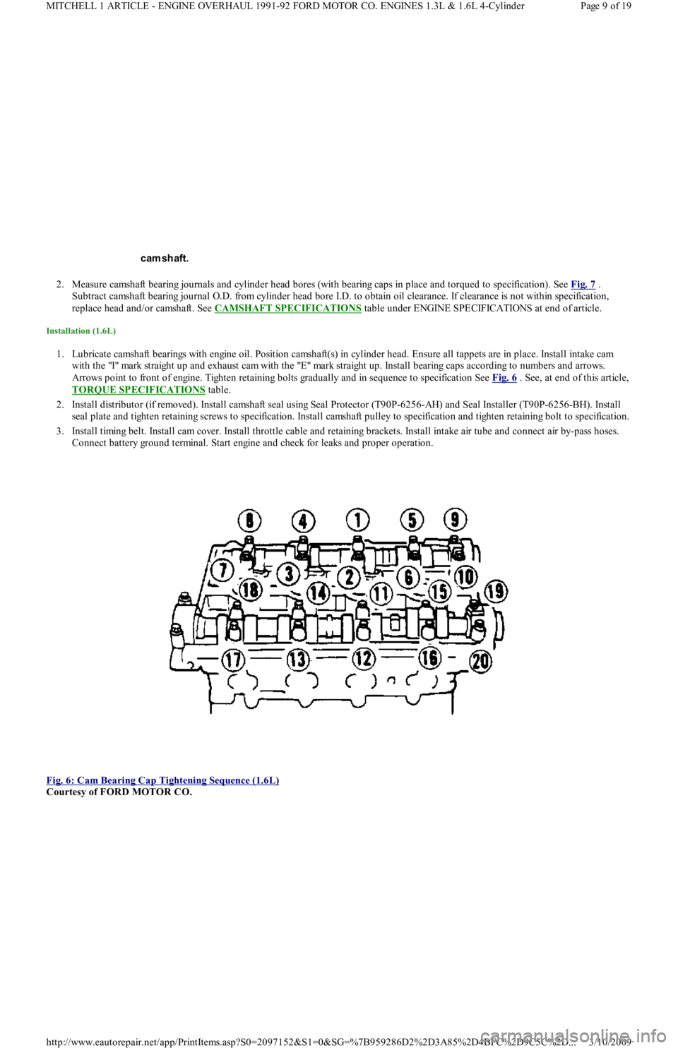
1. Lubricate camshaft bearings with engine oil. Position camshaft(s) in cylinder head. Ensure all tappets are in place. Install intake cam
with the "I" mark straight up and exhaust cam with the "E" mark straight up. Install bearing caps according to numbers and arrows.
Arrows point to front of engine. Tighten retaining bolts gradually and in sequence to specification See Fig. 6
. See, at end of this article,
TORQUE SPECIFICATIONS
table.
2. Install distributor (if removed). Install camshaft seal using Seal Protector (T90P-6256-AH) and Seal Installer (T90P-6256-BH). Install
seal plate and tighten retaining screws to specification. Install camshaft pulley to specification and tighten retaining bolt to specification.
3. Install timing belt. Install cam cover. Install throttle cable and retaining brackets. Install intake air tube and connect air by-pass hoses.
Connect battery ground terminal. Start engine and check for leaks and proper operation.
Fig. 6: Cam Bearing Cap Tightening Sequence (1.6L)
Courtesy of FORD MOTOR CO. cam shaft.
Page 9 of 19 MITCHELL 1 ARTICLE - ENGINE OVERHAUL 1991-92 FORD MOTOR CO. ENGINES 1.3L & 1.6L 4-Cylinder
3/10/2009 http://www.eautorepair.net/app/PrintItems.asp?S0=2097152&S1=0&SG=%7B959286D2%2D3A85%2D4BFC%2D9C5C%2D
...