lock FORD FIESTA 1989 Service Repair Manual
[x] Cancel search | Manufacturer: FORD, Model Year: 1989, Model line: FIESTA, Model: FORD FIESTA 1989Pages: 296, PDF Size: 10.65 MB
Page 183 of 296
7Using a suitable socket, firmly press the
primary piston into the master cylinder until
the secondary piston retaining pin becomes
visible through the secondary piston reservoir
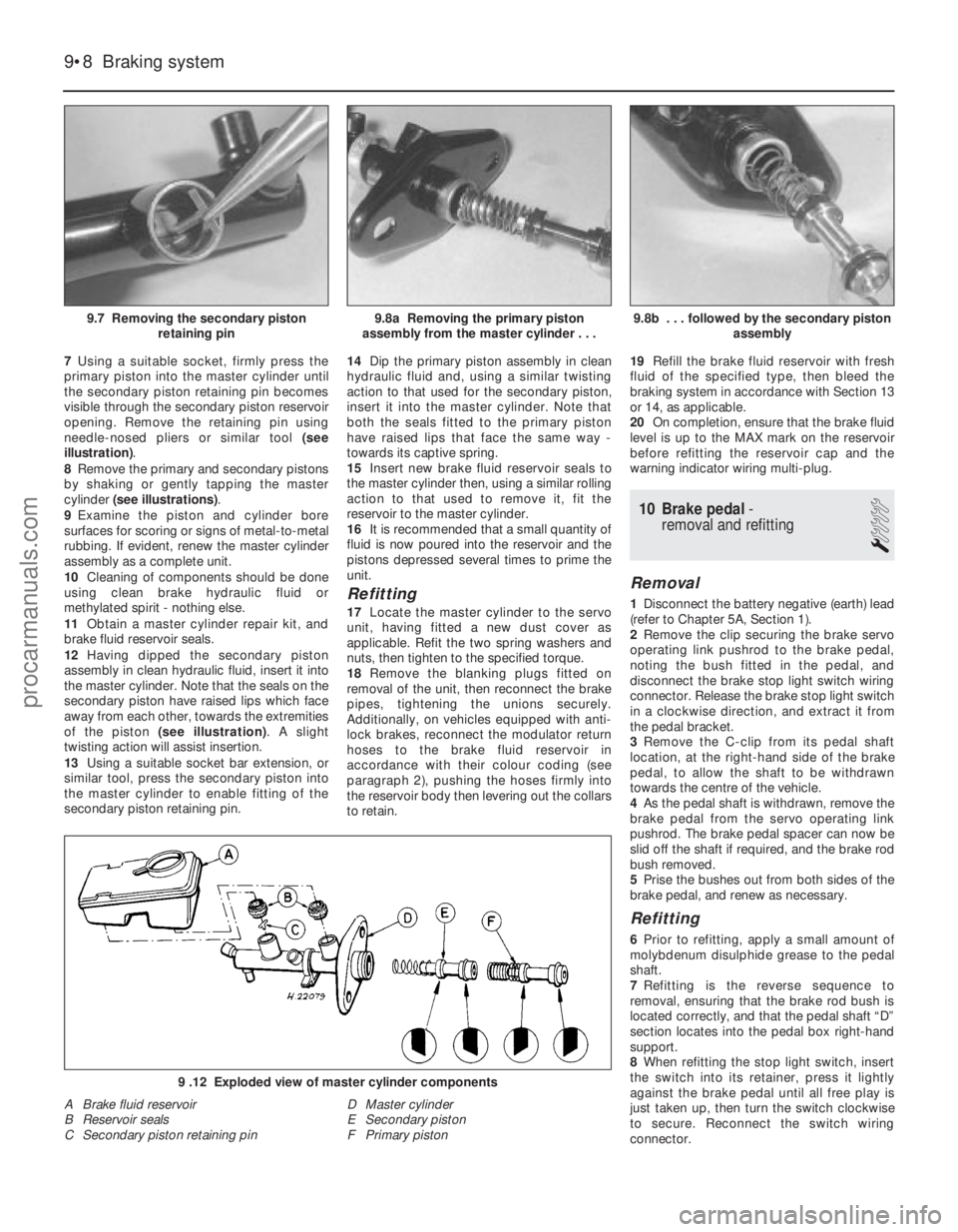
opening. Remove the retaining pin using
needle-nosed pliers or similar tool (see
illustration) .
8 Remove the primary and secondary pistons
by shaking or gently tapping the master
cylinder (see illustrations) .
9 Examine the piston and cylinder bore
surfaces for scoring or signs of metal-to-metal
rubbing. If evident, renew the master cylinder
assembly as a complete unit.
10 Cleaning of components should be done
using clean brake hydraulic fluid or
methylated spirit - nothing else.
11 Obtain a master cylinder repair kit, and
brake fluid reservoir seals.
12 Having dipped the secondary piston
assembly in clean hydraulic fluid, insert it into
the master cylinder. Note that the seals on the
secondary piston have raised lips which face
away from each other, towards the extremities
of the piston (see illustration) . A slight
twisting action will assist insertion.
13 Using a suitable socket bar extension, or
similar tool, press the secondary piston into
the master cylinder to enable fitting of the
secondary piston retaining pin. 14
Dip the primary piston assembly in clean
hydraulic fluid and, using a similar twisting
action to that used for the secondary piston,
insert it into the master cylinder. Note that
both the seals fitted to the primary piston
have raised lips that face the same way -
towards its captive spring.
15 Insert new brake fluid reservoir seals to
the master cylinder then, using a similar rolling
action to that used to remove it, fit the
reservoir to the master cylinder.
16 It is recommended that a small quantity of
fluid is now poured into the reservoir and the
pistons depressed several times to prime the
unit.
Refitting
17 Locate the master cylinder to the servo
unit, having fitted a new dust cover as
applicable. Refit the two spring washers and
nuts, then tighten to the specified torque.
18 Remove the blanking plugs fitted on
removal of the unit, then reconnect the brake
pipes, tightening the unions securely.
Additionally, on vehicles equipped with anti-
lock brakes, reconnect the modulator return
hoses to the brake fluid reservoir in
accordance with their colour coding (see
paragraph 2), pushing the hoses firmly into
the reservoir body then levering out the collars
to retain. 19
Refill the brake fluid reservoir with fresh
fluid of the specified type, then bleed the
braking system in accordance with Section 13
or 14, as applicable.
20 On completion, ensure that the brake fluid
level is up to the MAX mark on the reservoir
before refitting the reservoir cap and the
warning indicator wiring multi-plug.
10 Brake pedal -
removal and refitting
1
Removal
1 Disconnect the battery negative (earth) lead
(refer to Chapter 5A, Section 1).
2 Remove the clip securing the brake servo
operating link pushrod to the brake pedal,
noting the bush fitted in the pedal, and
disconnect the brake stop light switch wiring
connector. Release the brake stop light switch
in a clockwise direction, and extract it from
the pedal bracket.
3 Remove the C-clip from its pedal shaft
location, at the right-hand side of the brake
pedal, to allow the shaft to be withdrawn
towards the centre of the vehicle.
4 As the pedal shaft is withdrawn, remove the
brake pedal from the servo operating link
pushrod. The brake pedal spacer can now be
slid off the shaft if required, and the brake rod
bush removed.
5 Prise the bushes out from both sides of the
brake pedal, and renew as necessary.
Refitting
6 Prior to refitting, apply a small amount of
molybdenum disulphide grease to the pedal
shaft.
7 Refitting is the reverse sequence to
removal, ensuring that the brake rod bush is
located correctly, and that the pedal shaft “D”
section locates into the pedal box right-hand
support.
8 When refitting the stop light switch, insert
the switch into its retainer, press it lightly
against the brake pedal until all free play is
just taken up, then turn the switch clockwise
to secure. Reconnect the switch wiring
connector.
9•8 Braking system
9 .12 Exploded view of master cylinder components
A Brake fluid reservoir
B Reservoir seals
C Secondary piston retaining pin D Master cylinder
E Secondary piston
F Primary piston
9.8b . . . followed by the secondary piston
assembly9.8a Removing the primary piston
assembly from the master cylinder . . .9.7 Removing the secondary piston retaining pin
1595Ford Fiesta Remakeprocarmanuals.com
http://vnx.su
Page 184 of 296
11 Brake pedal-to-servo cross-link - removal and refitting
3
Removal
1Disconnect the battery negative (earth) lead
(refer to Chapter 5A, Section 1).
2 Disconnect the cross link pushrod from its
brake pedal location by removing the retaining
clip on the brake pedal, noting the bush fitted
in the pedal.
3 Disconnect the wiring multi-plug from the
fluid level warning indicator in the master
cylinder reservoir filler cap, then remove the
filler cap. Note that the filler cap must not be
inverted. The brake fluid should now be
removed from the reservoir.
4 Identify each brake pipe and its connection
to the master cylinder. Unscrew the fluid pipe
to master cylinder union nuts and disconnect
the pipes. On models equipped with anti-lock
brakes, disconnect the modulator return
hoses from the brake fluid reservoir, collecting
fluid spillage from the hoses in a suitable tray.
The modulator return hose unions should be
disconnected by first pushing the hose into
the reservoir, then retaining the collar against
the reservoir body whilst withdrawing the
hose. Note that the modulator return hoses
are colour coded - the left-hand modulator
has a black return hose and connector, and
should be fitted to the forward section of the
reservoir, whilst the right-hand modulator has
a grey return hose and connector, and should
be fitted to the rear section of the reservoir.
5 Disconnect the vacuum hose from the
servo unit by carefully levering between the
hose connector and the servo housing collar
with a screwdriver.
6 Lift up the flap of sound insulation on the bulkhead, in the passenger side footwell, to
expose the servo mounting bracket retaining
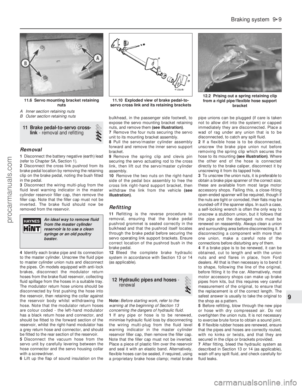
nuts, and remove them
(see illustration).
7 Remove the four nuts securing the servo
unit to its mounting bracket assembly.
8 Pull the servo/master cylinder assembly
forward and remove the inner servo support
bracket.
9 Remove the spring clip and clevis pin
securing the servo actuating rod to the cross
link, then lift out the servo/master cylinder
assembly.
10 Remove the two nuts on the right-hand
side of the pedal box assembly to free the
cross link right-hand support bracket, then
withdraw the link from the vehicle (see
illustration) .
Refitting
11Refitting is the reverse procedure to
removal, ensuring that the brake pedal
pushrod grommet is seated correctly in the
bulkhead and that the pushrod itself locates
through the brake pedal before securing the
servo operating link support brackets. Ensure
correct location of the pushrod bush in the
brake pedal.
12 Bleed the complete brake hydraulic
system in accordance with Section 13 or 14
(as applicable).
12 Hydraulic pipes and hoses -
renewal
2
Note: Before starting work, refer to the
warning at the beginning of Section 13
concerning the dangers of hydraulic fluid.
1 If any pipe or hose is to be renewed,
minimise hydraulic fluid loss by disconnecting
the wiring multi-plug from the fluid level
warning indicator in the master cylinder
reservoir filler cap, then remove the filler cap.
Note that the filler cap must not be inverted.
Place a piece of plastic film over the reservoir
and seal it with an elastic band. Alternatively,
flexible hoses can be sealed, if required, using
a proprietary brake hose clamp; metal brake pipe unions can be plugged (if care is taken
not to allow dirt into the system) or capped
immediately they are disconnected. Place a
wad of rag under any union that is to be
disconnected, to catch any spilt fluid.
2
If a flexible hose is to be disconnected,
unscrew the brake pipe union nut before
removing the spring clip which secures the
hose to its mounting (see illustration). Where
the other end of the hose is connected
directly to the brake caliper, disconnect it by
unscrewing it from its tapped hole.
3 To unscrew the union nuts, it is preferable to
obtain a brake pipe spanner of the correct size;
these are available from most large motor
accessory shops. Failing this, a close-fitting
open-ended spanner will be required, though if
the nuts are tight or corroded, their flats may be
rounded-off if the spanner slips. In such a case,
a self-locking wrench is often the only way to
unscrew a stubborn union, but it follows that
the pipe and the damaged nuts must be
renewed on reassembly. Always clean a union
and surrounding area before disconnecting it. If
disconnecting a component with more than
one union, make a careful note of the
connections before disturbing any of them.
4 If a brake pipe is to be renewed, it can be
obtained, cut to length and with the union
nuts and end flares in place, from Ford
dealers. All that is then necessary is to bend it
to shape, following the line of the original,
before fitting it to the car. Alternatively, most
motor accessory shops can make up brake
pipes from kits, but this requires very careful
measurement of the original, to ensure that
the replacement is of the correct length. The
safest answer is usually to take the original to
the shop as a pattern.
5 Before refitting, blow through the new pipe
or hose with dry compressed air. Do not
overtighten the union nuts. It is not necessary
to exercise brute force to obtain a sound joint.
6 If flexible rubber hoses are renewed, ensure
that the pipes and hoses are correctly routed,
with no kinks or twists, and that they are
secured in the clips or brackets provided.
7 After fitting, bleed the hydraulic system as
described in Section 13 or 14 (as applicable),
wash off any spilt fluid, and check carefully for
fluid leaks.
Braking system 9•9
12.2 Prising out a spring retaining clip from a rigid pipe/flexible hose support bracket11.10 Exploded view of brake pedal-to-
servo cross link and its retaining brackets11.6 Servo mounting bracket retaining nuts
A Inner section retaining nuts
B Outer section retaining nuts
9
1595Ford Fiesta Remake
An ideal way to remove fluid from the master cylinder
reservoir is to use a clean
syringe or an old poultry
baster.
procarmanuals.com
http://vnx.su
Page 185 of 296
13 Hydraulic system- bleeding
(conventional braking system)
3
Note: For vehicles equipped with an anti-lock
braking system, refer to Section 14. Warning: Hydraulic fluid is
poisonous; wash off
immediately and thoroughly in
the case of skin contact, and
seek immediate medical advice if any fluid
is swallowed or gets into the eyes. Certain
types of hydraulic fluid are inflammable,
and may ignite when allowed into contact
with hot components; when servicing any
hydraulic system, it is safest to assume
that the fluid IS inflammable, and to take
precautions against the risk of fire as
though it is petrol that is being handled.
Hydraulic fluid is also an effective paint
stripper, and will attack plastics; if any is
spilt, it should be washed off immediately,
using copious quantities of clean water.
Finally, it is hygroscopic (it absorbs
moisture from the air). The more moisture
is absorbed by the fluid, the lower its
boiling point becomes, leading to a
dangerous loss of braking under hard use.
Old fluid may be contaminated and unfit
for further use. When topping-up or
renewing the fluid, always use the
recommended type, and ensure that it
comes from a freshly-opened sealed
container.
1 The correct operation of any hydraulic
system is only possible after removing all air
from the components and circuit; and this is
achieved by bleeding the system.
2 During the bleeding procedure, add only
clean, unused hydraulic fluid of the
recommended type; never re-use fluid that
has already been bled from the system.
Ensure that sufficient fluid is available before
starting work.
3 If there is any possibility of incorrect fluid
being already in the system, the brake
components and circuit must be flushed
completely with uncontaminated, correct
fluid, and new seals should be fitted
throughout the system.
4 If hydraulic fluid has been lost from the
system, or air has entered because of a leak,
ensure that the fault is cured before
proceeding further.
5 Park the vehicle on level ground, and apply
the handbrake. Switch off the engine, then
(where applicable) depress the brake pedal
several times to dissipate the vacuum from
the servo unit. Note:When bleeding the
system, the vehicle must maintain a level
attitude, ie not tilted in any manner, to ensure
that air is not trapped within the pressure
control valves. During certain operations in
this manual, instructions are given to bleed the
brake hydraulic system with the front or the
rear of the vehicle raised. In such cases raise
the rest of the vehicle so that it maintains a level attitude, but only if it is safe to do so. If it
is not possible to achieve this safely, complete
the remainder of the operation and bleed the
brake hydraulic system with the vehicle on its
wheels.
6
Check that all pipes and hoses are secure,
unions tight and bleed screws closed.
Remove the dust caps (where applicable), and
clean any dirt from around the bleed screws.
7 Disconnect the wiring multi-plug from the
fluid level warning indicator in the master
cylinder reservoir filler cap, then remove the
filler cap. Note that the filler cap must not be
inverted. Top-up the reservoir with the
specified fluid to the “Maximum” level (see
“Weekly Checks” ). Remember to maintain the
fluid level at least above the “Minimum” level
line throughout the procedure, otherwise
there is a risk of further air entering the
system.
8 There are a number of one-man, do-it-
yourself brake bleeding kits currently available
from motor accessory shops. It is
recommended that one of these kits is used
whenever possible, as they greatly simplify
the bleeding operation, and also reduce the
risk of expelled air and fluid being drawn back
into the system. If such a kit is not available,
the basic (two-man) method must be used,
which is described in detail below.
9 If a kit is to be used, prepare the vehicle as
described previously, and follow the kit
manufacturer’s instructions, as the procedure
may vary slightly according to the type being
used; generally, they are as outlined below in
the relevant sub-section.
10 Whichever method is used, the same
sequence must be followed (paragraphs 11
and 12) to ensure the removal of all air from
the system.
Bleeding sequence
11 If the system has been only partially
disconnected, and suitable precautions were
taken to minimise fluid loss, it should be
necessary to bleed only that part of the
system (ie the primary or secondary circuit).
12 If the complete system is to be bled, then
it is suggested that you work in the following
sequence: a) Right-hand front wheel.
b) Left-hand rear wheel.
c) Left-hand front wheel.
d) Right-hand rear wheel.
Bleeding - basic (two-man)
method
13 Collect a clean glass jar, a suitable length
of plastic or rubber tubing which is a tight fit
over the bleed screw, and a ring spanner to fit
the screw. The help of an assistant will also be
required.
14 Remove the dust cap from the first screw
in the sequence (if not already done). Fit a
suitable spanner and tube to the screw, place
the other end of the tube in the jar, and pour in
sufficient fluid to cover the end of the tube.
15 Ensure that the master cylinder reservoir fluid level is maintained at least above the
“Minimum” level throughout the procedure.
16
Have the assistant fully depress the brake
pedal several times to build up pressure, then
maintain it down on the final downstroke.
17 While pedal pressure is maintained,
unscrew the bleed screw (approximately one
turn) and allow the compressed fluid and air to
flow into the jar. The assistant should maintain
pedal pressure, following the pedal down to
the floor if necessary, and should not
release the pedal until instructed to do so.
When the flow stops, tighten the bleed screw
again. Have the assistant release the pedal
slowly, and recheck the reservoir fluid level.
18 Repeat the steps given in paragraphs 16
and 17 until the fluid emerging from the bleed
screw is free from air bubbles. If the master
cylinder has been drained and refilled, and air
is being bled from the first screw in the
sequence, allow at least five seconds between
cycles for the master cylinder passages to refill.
19 When no more air bubbles appear, tighten
the bleed screw securely, remove the tube
and spanner, and refit the dust cap (where
applicable). Do not overtighten the bleed
screw.
20 Repeat the procedure on the remaining
screws in the sequence, until all air is
removed from the system and the brake pedal
feels firm again.
Bleeding - using a one-way
valve kit
21 As their name implies, these kits consist of
a length of tubing with a one-way valve fitted,
to prevent expelled air and fluid being drawn
back into the system; some kits include a
translucent container, which can be positioned
so that the air bubbles can be more easily
seen flowing from the end of the tube.
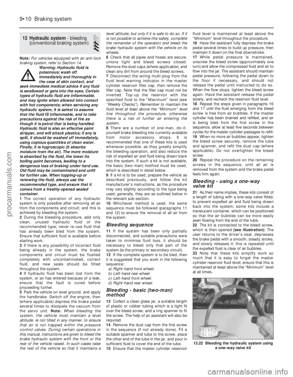
22 The kit is connected to the bleed screw,
which is then opened (see illustration). The
user returns to the driver’s seat, depresses
the brake pedal with a smooth, steady stroke,
and slowly releases it; this is repeated until
the expelled fluid is clear of air bubbles.
23 Note that these kits simplify work so
much that it is easy to forget the master
cylinder reservoir fluid level; ensure that this is
maintained at least above the “Minimum” level
at all times.
9•10 Braking system
13.22 Bleeding the hydraulic system using a one-way valve kit
1595Ford Fiesta Remakeprocarmanuals.com
http://vnx.su
Page 186 of 296
Bleeding - using a pressure-
bleeding kit
24These kits are usually operated by the
reservoir of pressurised air contained in the
spare tyre. However, note that it will probably
be necessary to reduce the pressure to a
lower level than normal; refer to the
instructions supplied with the kit.
25 By connecting a pressurised, fluid-filled
container to the master cylinder reservoir,
bleeding can be carried out simply by opening
each screw in turn (in the specified sequence),
and allowing the fluid to flow out until no more
air bubbles can be seen in the expelled fluid.
26 This method has the advantage that the
large reservoir of fluid provides an additional
safeguard against air being drawn into the
system during bleeding.
27 Pressure-bleeding is particularly effective
when bleeding “difficult” systems, or when
bleeding the complete system at the time of
routine fluid renewal.
All methods
28 When bleeding is complete, and firm
pedal feel is restored, wash off any spilt fluid,
tighten the bleed screws securely, and refit
their dust caps.
29 Check the hydraulic fluid level in the
master cylinder reservoir, and top-up if
necessary.
30 Discard any hydraulic fluid that has been
bled from the system; it will not be fit for re-
use.
31 Check the feel of the brake pedal. If it
feels at all spongy, air must still be present in
the system, and further bleeding is required.
Failure to bleed satisfactorily after a
reasonable repetition of the bleeding
procedure may be due to worn master
cylinder seals.
14 Hydraulic system - bleeding
(anti-lock braking system)
3
Note: Before starting work, refer to the
warning at the beginning of Section 13
concerning the dangers of hydraulic fluid.
1 On vehicles equipped with the anti-lock braking system there are two bleed
procedures possible, depending on which
part of the brake hydraulic system has been
disturbed.
2
If any one of the following conditions are
present, bleed procedure A should be
adopted: a) A modulator has been removed.
b) A modulator return hose (between
modulator and brake fluid reservoir) has
been drained.
c) The rigid brake pipes have been disconnected from a modulator.
3 If any one of the following conditions are
present, bleed procedure B should be
adopted: a) Any condition where the master cylinder
has been removed or drained, providing
that the modulator return hoses have not
lost their head of fluid.
b) Removal or disconnection of any of the
basic braking system components ie,
brake caliper, flexible hose or rigid pipe,
wheel cylinder, or load-apportioning
valve.
Bleed procedure A
4Raise the vehicle on ramps, or drive it over
an inspection pit, so that working clearance
may be obtained with the full weight of the
vehicle on its roadwheels. Remove the one-
piece undertray, as applicable, by turning its
bayonet-type fasteners and, on XR2i models,
remove the front suspension crossmember
(see Chapter 10).
5 Disconnect the wiring multi-plug from the
fluid level warning indicator in the master
cylinder reservoir filler cap, then remove the
filler cap. Note that the filler cap must not be
inverted. Top-up the brake fluid reservoir to
the MAX mark using fresh fluid of the
specified type (see “Weekly Checks”), and
keep it topped up throughout the bleeding
procedure.
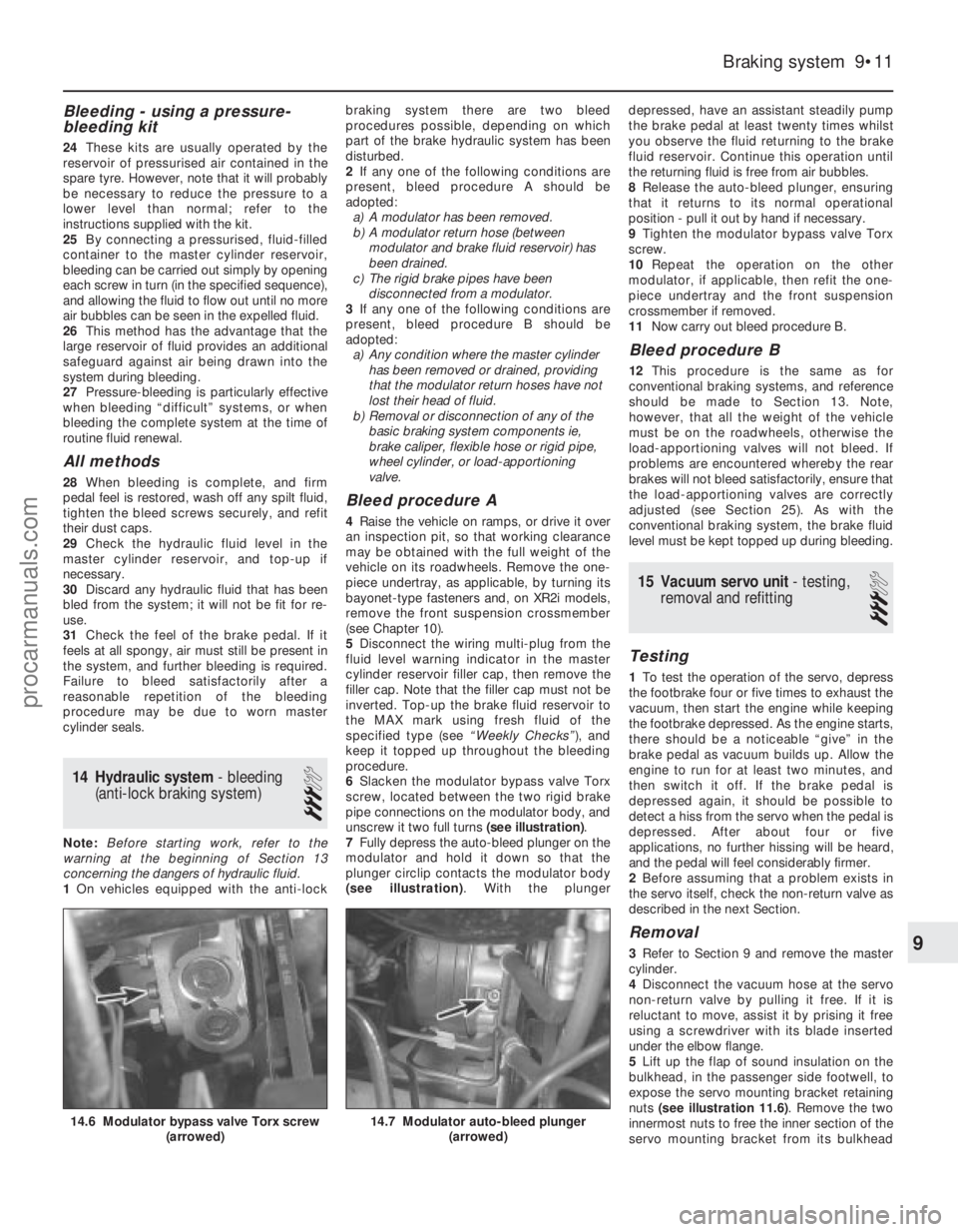
6 Slacken the modulator bypass valve Torx
screw, located between the two rigid brake
pipe connections on the modulator body, and
unscrew it two full turns (see illustration).
7 Fully depress the auto-bleed plunger on the
modulator and hold it down so that the
plunger circlip contacts the modulator body
(see illustration) . With the plunger depressed, have an assistant steadily pump
the brake pedal at least twenty times whilst
you observe the fluid returning to the brake
fluid reservoir. Continue this operation until
the returning fluid is free from air bubbles.
8
Release the auto-bleed plunger, ensuring
that it returns to its normal operational
position - pull it out by hand if necessary.
9 Tighten the modulator bypass valve Torx
screw.
10 Repeat the operation on the other
modulator, if applicable, then refit the one-
piece undertray and the front suspension
crossmember if removed.
11 Now carry out bleed procedure B.
Bleed procedure B
12This procedure is the same as for
conventional braking systems, and reference
should be made to Section 13. Note,
however, that all the weight of the vehicle
must be on the roadwheels, otherwise the
load-apportioning valves will not bleed. If
problems are encountered whereby the rear
brakes will not bleed satisfactorily, ensure that
the load-apportioning valves are correctly
adjusted (see Section 25). As with the
conventional braking system, the brake fluid
level must be kept topped up during bleeding.
15 Vacuum servo unit - testing,
removal and refitting
3
Testing
1 To test the operation of the servo, depress
the footbrake four or five times to exhaust the
vacuum, then start the engine while keeping
the footbrake depressed. As the engine starts,
there should be a noticeable “give” in the
brake pedal as vacuum builds up. Allow the
engine to run for at least two minutes, and
then switch it off. If the brake pedal is
depressed again, it should be possible to
detect a hiss from the servo when the pedal is
depressed. After about four or five
applications, no further hissing will be heard,
and the pedal will feel considerably firmer.
2 Before assuming that a problem exists in
the servo itself, check the non-return valve as
described in the next Section.
Removal
3 Refer to Section 9 and remove the master
cylinder.
4 Disconnect the vacuum hose at the servo
non-return valve by pulling it free. If it is
reluctant to move, assist it by prising it free
using a screwdriver with its blade inserted
under the elbow flange.
5 Lift up the flap of sound insulation on the
bulkhead, in the passenger side footwell, to
expose the servo mounting bracket retaining
nuts (see illustration 11.6) . Remove the two
innermost nuts to free the inner section of the
servo mounting bracket from its bulkhead
Braking system 9•11
14.7 Modulator auto-bleed plunger (arrowed)14.6 Modulator bypass valve Torx screw (arrowed)
9
1595Ford Fiesta Remakeprocarmanuals.com
http://vnx.su
Page 189 of 296
needed not to spill the fluid onto the hands -
wear suitable protective gloves. Plug or cap
the disconnected pipes and valve openings,
to prevent dirt ingress and further fluid loss.
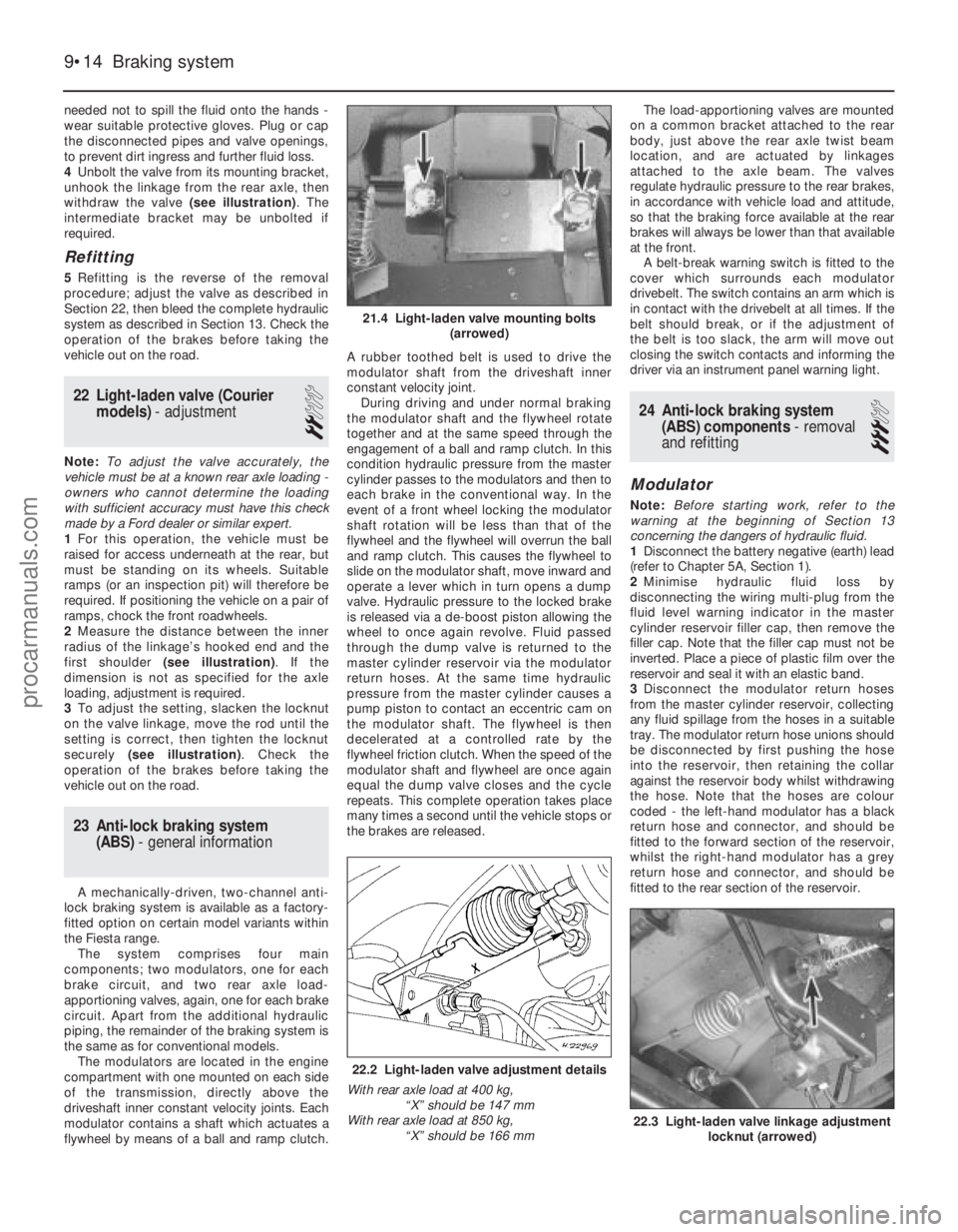
4Unbolt the valve from its mounting bracket,
unhook the linkage from the rear axle, then
withdraw the valve (see illustration). The
intermediate bracket may be unbolted if
required.
Refitting
5 Refitting is the reverse of the removal
procedure; adjust the valve as described in
Section 22, then bleed the complete hydraulic
system as described in Section 13. Check the
operation of the brakes before taking the
vehicle out on the road.
22 Light-laden valve (Courier models) - adjustment
2
Note:To adjust the valve accurately, the
vehicle must be at a known rear axle loading -
owners who cannot determine the loading
with sufficient accuracy must have this check
made by a Ford dealer or similar expert.
1 For this operation, the vehicle must be
raised for access underneath at the rear, but
must be standing on its wheels. Suitable
ramps (or an inspection pit) will therefore be
required. If positioning the vehicle on a pair of
ramps, chock the front roadwheels.
2 Measure the distance between the inner
radius of the linkage’s hooked end and the
first shoulder (see illustration) . If the
dimension is not as specified for the axle
loading, adjustment is required.
3 To adjust the setting, slacken the locknut
on the valve linkage, move the rod until the
setting is correct, then tighten the locknut
securely (see illustration) . Check the
operation of the brakes before taking the
vehicle out on the road.
23 Anti-lock braking system (ABS) - general information
A mechanically-driven, two-channel anti-
lock braking system is available as a factory-
fitted option on certain model variants within
the Fiesta range.
The system comprises four main
components; two modulators, one for each
brake circuit, and two rear axle load-
apportioning valves, again, one for each brake
circuit. Apart from the additional hydraulic
piping, the remainder of the braking system is
the same as for conventional models. The modulators are located in the engine
compartment with one mounted on each side
of the transmission, directly above the
driveshaft inner constant velocity joints. Each
modulator contains a shaft which actuates a
flywheel by means of a ball and ramp clutch. A rubber toothed belt is used to drive the
modulator shaft from the driveshaft inner
constant velocity joint.
During driving and under normal braking
the modulator shaft and the flywheel rotate
together and at the same speed through the
engagement of a ball and ramp clutch. In this
condition hydraulic pressure from the master
cylinder passes to the modulators and then to
each brake in the conventional way. In the
event of a front wheel locking the modulator
shaft rotation will be less than that of the
flywheel and the flywheel will overrun the ball
and ramp clutch. This causes the flywheel to
slide on the modulator shaft, move inward and
operate a lever which in turn opens a dump
valve. Hydraulic pressure to the locked brake
is released via a de-boost piston allowing the
wheel to once again revolve. Fluid passed
through the dump valve is returned to the
master cylinder reservoir via the modulator
return hoses. At the same time hydraulic
pressure from the master cylinder causes a
pump piston to contact an eccentric cam on
the modulator shaft. The flywheel is then
decelerated at a controlled rate by the
flywheel friction clutch. When the speed of the
modulator shaft and flywheel are once again
equal the dump valve closes and the cycle
repeats. This complete operation takes place
many times a second until the vehicle stops or
the brakes are released. The load-apportioning valves are mounted
on a common bracket attached to the rear
body, just above the rear axle twist beam
location, and are actuated by linkages
attached to the axle beam. The valves
regulate hydraulic pressure to the rear brakes,
in accordance with vehicle load and attitude,
so that the braking force available at the rear
brakes will always be lower than that available
at the front. A belt-break warning switch is fitted to the
cover which surrounds each modulator
drivebelt. The switch contains an arm which is
in contact with the drivebelt at all times. If the
belt should break, or if the adjustment of
the belt is too slack, the arm will move out
closing the switch contacts and informing the
driver via an instrument panel warning light.
24 Anti-lock braking system (ABS) components - removal
and refitting
3
Modulator
Note: Before starting work, refer to the
warning at the beginning of Section 13
concerning the dangers of hydraulic fluid.
1 Disconnect the battery negative (earth) lead
(refer to Chapter 5A, Section 1).
2 Minimise hydraulic fluid loss by
disconnecting the wiring multi-plug from the
fluid level warning indicator in the master
cylinder reservoir filler cap, then remove the
filler cap. Note that the filler cap must not be
inverted. Place a piece of plastic film over the
reservoir and seal it with an elastic band.
3 Disconnect the modulator return hoses
from the master cylinder reservoir, collecting
any fluid spillage from the hoses in a suitable
tray. The modulator return hose unions should
be disconnected by first pushing the hose
into the reservoir, then retaining the collar
against the reservoir body whilst withdrawing
the hose. Note that the hoses are colour
coded - the left-hand modulator has a black
return hose and connector, and should be
fitted to the forward section of the reservoir,
whilst the right-hand modulator has a grey
return hose and connector, and should be
fitted to the rear section of the reservoir.
9•14 Braking system
22.3 Light-laden valve linkage adjustment locknut (arrowed)
22.2 Light-laden valve adjustment details
With rear axle load at 400 kg, “X” should be 147 mm
With rear axle load at 850 kg,
“X” should be 166 mm
21.4 Light-laden valve mounting bolts (arrowed)
1595Ford Fiesta Remakeprocarmanuals.com
http://vnx.su
Page 195 of 296
:Steel . . . . . . . . . . . . . . . . . . . . . . . . . . . . . . . . . . . .\
. . . . . . . . . . . . . . 13 x 4.5, 13 x 5, 13 x 5.5
Alloy . .")
Roadwheels
Wheel types and sizes (dependent on model):Steel . . . . . . . . . . . . . . . . . . . . . . . . . . . . . . . . . . . .\
. . . . . . . . . . . . . . 13 x 4.5, 13 x 5, 13 x 5.5
Alloy . . . . . . . . . . . . . . . . . . . . . . . . . . . . . . . . . . . .\
. . . . . . . . . . . . . . 13 x 5.5, 14 x 5.5
Tyres
Tyre sizes (dependent on model) . . . . . . . . . . . . . . . . . . . . . . . . . . . . . . 135 R 13, 145 R 13, 155/70 R 13, 165/55 R 13, 165/65 R 13, 175/60 R 13, 185/55 R 14 or 185/60 R 13
Tyre pressures . . . . . . . . . . . . . . . . . . . . . . . . . . . . . . . . . . . .\
. . . . . . . . See “Weekly Checks”
Torque wrench settingsNmlbf ft
Front suspension
Hub/driveshaft retaining nut . . . . . . . . . . . . . . . . . . . . . . . . . . . . . . . . . . 205 to 235 151 to 173
Lower arm balljoint-to-spindle carrier pinch bolt . . . . . . . . . . . . . . . . . . 48 to 60 35 to 44
Front suspension strut to spindle carrier pinch-bolt . . . . . . . . . . . . . . . 80 to 90 59 to 66
Anti-roll bar link to front suspension strut nut . . . . . . . . . . . . . . . . . . . . 41 to 58 30 to 43
Anti-roll bar link to anti-roll bar nut . . . . . . . . . . . . . . . . . . . . . . . . . . . . . 41 to 58 30 to 43
Anti-roll bar retaining clamp bolts to lower arm . . . . . . . . . . . . . . . . . . . 20 to 28 15 to 21
Front suspension strut top-mount retaining nut . . . . . . . . . . . . . . . . . . . 40 to 52 30 to 38
Front suspension strut spring retaining nut . . . . . . . . . . . . . . . . . . . . . . 52 to 65 38 to 48
Front suspension crossmember bolts (XR2i only) . . . . . . . . . . . . . . . . . 80 to 90 59 to 66
Lower arm to lower arm mounting bracket bolts (using torque-to-yield
method with vehicle standing on its wheels): Stage 1 . . . . . . . . . . . . . . . . . . . . . . . . . . . . . . . . . . . .\
. . . . . . . . . . . . 5037
Stage 2 . . . . . . . . . . . . . . . . . . . . . . . . . . . . . . . . . . . .\
. . . . . . . . . . . . Slacken completely
Stage 3 . . . . . . . . . . . . . . . . . . . . . . . . . . . . . . . . . . . .\
. . . . . . . . . . . . 5037
Stage 4 . . . . . . . . . . . . . . . . . . . . . . . . . . . . . . . . . . . .\
. . . . . . . . . . . . Tighten through a further 90°
Rear suspension (all models except Courier)
Rear hub bearing retaining nut . . . . . . . . . . . . . . . . . . . . . . . . . . . . . . . . 250 to 290 184 to 214
Rear drum/hub to axle flange bolts . . . . . . . . . . . . . . . . . . . . . . . . . . . . 56 to 76 41 to 56
Rear axle to body mounting bracket bolts . . . . . . . . . . . . . . . . . . . . . . . 41 to 58 30 to 43
Rear axle trailing arm bush bolt* . . . . . . . . . . . . . . . . . . . . . . . . . . . . . . . 58 to 79 43 to 58
Rear strut top-mount retaining nuts . . . . . . . . . . . . . . . . . . . . . . . . . . . . 28 to 40 20 to 30
Rear strut-to-axle mounting bolt . . . . . . . . . . . . . . . . . . . . . . . . . . . . . . 102 to 138 75 to 102
Rear strut spring retaining through-bolt . . . . . . . . . . . . . . . . . . . . . . . . . 41 to 58 30 to 42
Anti-roll bar front mounting bolts . . . . . . . . . . . . . . . . . . . . . . . . . . . . . . 41 to 58 30 to 42
Anti-roll bar rear mounting bolts . . . . . . . . . . . . . . . . . . . . . . . . . . . . . . . 88 to 113 65 to 83
Load-apportioning valve operating link to axle beam . . . . . . . . . . . . . . 21 to 28 15 to 21
*Torque to be measured from the bolt head (not the nut)
Rear suspension (Courier models)
Rear hub bearing retaining nut . . . . . . . . . . . . . . . . . . . . . . . . . . . . . . . . 250 to 290 184 to 214
Shock absorber upper mounting . . . . . . . . . . . . . . . . . . . . . . . . . . . . . . 102 to 138 75 to 102
Shock absorber lower mounting . . . . . . . . . . . . . . . . . . . . . . . . . . . . . . 70 to 97 52 to 72
Rear suspension mounting bracket bolts . . . . . . . . . . . . . . . . . . . . . . . . 70 to 97 52 to 72
Manual steering
Steering gear to bulkhead . . . . . . . . . . . . . . . . . . . . . . . . . . . . . . . . . . . 70 to 97 57 to 72
Track rod end balljoint to spindle carrier steering arm . . . . . . . . . . . . . . 25 to 30 18 to 22
Track rod locknut to track rod end balljoint . . . . . . . . . . . . . . . . . . . . . . 57 to 68 42 to 50
Steering wheel to column shaft bolt . . . . . . . . . . . . . . . . . . . . . . . . . . . . 45 to 55 33 to 40
Steering column mounting nuts . . . . . . . . . . . . . . . . . . . . . . . . . . . . . . . 10 to 14 7 to 10
Steering column universal joint pinch-bolt . . . . . . . . . . . . . . . . . . . . . . . 45 to 56 33 to 41
Power steering
Steering wheel to column shaft bolt . . . . . . . . . . . . . . . . . . . . . . . . . . . . 5037
Steering gear to bulkhead . . . . . . . . . . . . . . . . . . . . . . . . . . . . . . . . . . . 8462
Steering gear fluid pipe unions . . . . . . . . . . . . . . . . . . . . . . . . . . . . . . . . 3123
Steering gear flexible coupling pinch-bolt . . . . . . . . . . . . . . . . . . . . . . . 5138
Track rod end balljoint to spindle carrier steering arm . . . . . . . . . . . . . . 2619
Track rod locknut to track rod end balljoint . . . . . . . . . . . . . . . . . . . . . . 6346
Steering pump mounting bolts . . . . . . . . . . . . . . . . . . . . . . . . . . . . . . . . 2518
Steering pump pulley bolts . . . . . . . . . . . . . . . . . . . . . . . . . . . . . . . . . . . 2518
High pressure fluid pipe to pump union . . . . . . . . . . . . . . . . . . . . . . . . . 6548
High pressure fluid pipe coupling joint . . . . . . . . . . . . . . . . . . . . . . . . . . 1713
Steering column mounting nuts . . . . . . . . . . . . . . . . . . . . . . . . . . . . . . . 129
Roadwheel nuts
All models . . . . . . . . . . . . . . . . . . . . . . . . . . . . . . . . . . . .\
. . . . . . . . . . . . 70 to 110 52 to 74
10•2 Suspension and steering
1595Ford Fiesta Remakeprocarmanuals.com
http://vnx.su
Page 196 of 296
1 General information
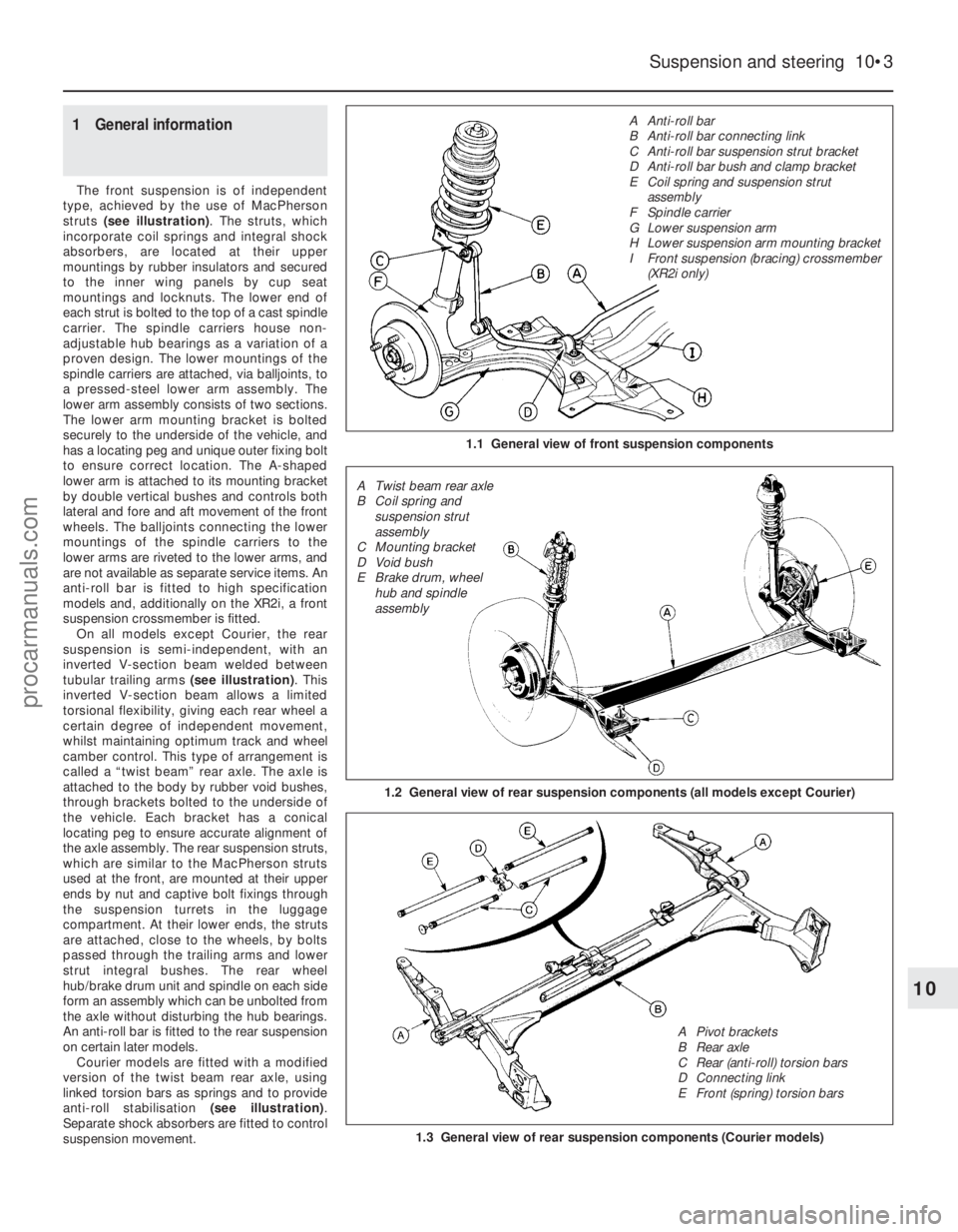
The front suspension is of independent
type, achieved by the use of MacPherson
struts (see illustration) . The struts, which
incorporate coil springs and integral shock
absorbers, are located at their upper
mountings by rubber insulators and secured
to the inner wing panels by cup seat
mountings and locknuts. The lower end of
each strut is bolted to the top of a cast spindle
carrier. The spindle carriers house non-
adjustable hub bearings as a variation of a
proven design. The lower mountings of the
spindle carriers are attached, via balljoints, to
a pressed-steel lower arm assembly. The
lower arm assembly consists of two sections.
The lower arm mounting bracket is bolted
securely to the underside of the vehicle, and
has a locating peg and unique outer fixing bolt
to ensure correct location. The A-shaped
lower arm is attached to its mounting bracket
by double vertical bushes and controls both
lateral and fore and aft movement of the front
wheels. The balljoints connecting the lower
mountings of the spindle carriers to the
lower arms are riveted to the lower arms, and
are not available as separate service items. An
anti-roll bar is fitted to high specification
models and, additionally on the XR2i, a front
suspension crossmember is fitted. On all models except Courier, the rear
suspension is semi-independent, with an
inverted V-section beam welded between
tubular trailing arms (see illustration). This
inverted V-section beam allows a limited
torsional flexibility, giving each rear wheel a
certain degree of independent movement,
whilst maintaining optimum track and wheel
camber control. This type of arrangement is
called a “twist beam” rear axle. The axle is
attached to the body by rubber void bushes,
through brackets bolted to the underside of
the vehicle. Each bracket has a conical
locating peg to ensure accurate alignment of
the axle assembly. The rear suspension struts,
which are similar to the MacPherson struts
used at the front, are mounted at their upper
ends by nut and captive bolt fixings through
the suspension turrets in the luggage
compartment. At their lower ends, the struts
are attached, close to the wheels, by bolts
passed through the trailing arms and lower
strut integral bushes. The rear wheel
hub/brake drum unit and spindle on each side
form an assembly which can be unbolted from
the axle without disturbing the hub bearings.
An anti-roll bar is fitted to the rear suspension
on certain later models.
Courier models are fitted with a modified
version of the twist beam rear axle, using
linked torsion bars as springs and to provide
anti-roll stabilisation (see illustration).
Separate shock absorbers are fitted to control
suspension movement.
Suspension and steering 10•3
1.1 General view of front suspension components
1.3 General view of rear suspension components (Courier models)
1.2 General view of rear suspension components (all models except Cour\
ier)
10
1595Ford Fiesta Remake A Anti-roll bar
B Anti-roll bar connecting link
C Anti-roll bar suspension strut bracket
D Anti-roll bar bush and clamp bracket
E Coil spring and suspension strut
assembly
F Spindle carrier
G Lower suspension arm
H Lower suspension arm mounting bracket
I Front suspension (bracing) crossmember (XR2i only)
A Twist beam rear axle
B Coil spring and suspension strut
assembly
C Mounting bracket
D Void bush
E Brake drum, wheel hub and spindle
assembly
A Pivot brackets
B Rear axle
C Rear (anti-roll) torsion bars
D Connecting link
E Front (spring) torsion barsprocarmanuals.com
http://vnx.su
Page 197 of 296
On all models, the steering is of
conventional rack-and-pinion type,
incorporating a safety system of convoluted
column tube and double universally-jointed
lower steering shaft links. The steering column tube is supported at its
upper end by bracketry, and at its lower end by
a nylon support bush. The steering shaft is
supported within the column tube by two
support bearings, one at either end of the tube. The steering rack assembly is located on
the bulkhead. Steering input is transmitted,
via the steering shaft, to the pinion which
meshes with the teeth on the rack. The pinion transferring the steering input
moves the rack within its housing tube,
withdrawing and extending the track rods
attached to either end of the rack by balljoints.
This movement is transferred, by balljoints in
the track rod ends, to the steering arms on the spindle carriers which direct the roadwheels.
From the 1994 model year onwards, power
steering is available as standard or optional
equipment on certain models.
2 Front spindle carrier -
removal and refitting
3
Removal
Note: A new hub/driveshaft retaining nut will
be required for refitting.
1 Remove the wheel trim from the front
roadwheel on the side concerned, then using
a small pin punch, peen back the locking
portion of the front hub/driveshaft nut. Loosen
off the nut about half-a-turn.
2 Loosen off the front roadwheel retaining
nuts on the side concerned.
3 Chock the rear wheels then jack up the
front of the car and support it on axle stands
(see “Jacking and Vehicle Support” ). Remove
the appropriate roadwheel, and unscrew and
remove the hub/driveshaft retaining nut and
washer.
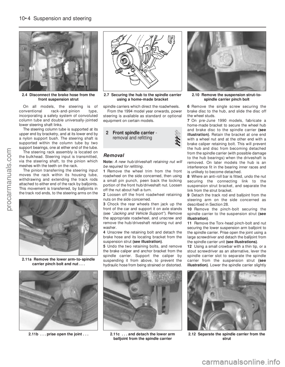
4 Unscrew the retaining bolt and detach the
brake hose and its locating bracket from the
suspension strut (see illustration).
5 Undo the two retaining bolts, and remove
the brake caliper and anchor bracket from the
spindle carrier. Support the caliper by
suspending it from above, to prevent the
hydraulic hose from being strained or distorted. 6
Remove the single screw securing the
brake disc to the hub, and slide the disc off
the wheel studs.
7 On pre-June 1990 models, fabricate a
home-made bracket to secure the wheel hub
and brake disc to the spindle carrier (see
illustration) . Retain the bracket at one end
with a wheel nut and at the other end with a
brake caliper retaining bolt. This will prevent
the hub and disc from becoming detached
from the spindle carrier (with possible damage
to the hub bearings) when the driveshaft is
removed. On later models the hub is an
interference fit in the bearing inner races and
is unlikely to become detached.
8 Where an anti-roll bar is fitted, undo the nut
securing the connecting link to the
suspension strut bracket, and separate the
link from the strut bracket.
9 Detach the track rod end balljoint from the
steering arm on the side concerned as
described in Section 28.
10 Remove the pinch-bolt securing the
spindle carrier to the suspension strut (see
illustration) .
11 Remove the Torx-head pinch-bolt and nut
securing the lower suspension arm balljoint to
the spindle carrier. Prise open the joint using a
large screwdriver and detach the balljoint from
the spindle carrier unit (see illustrations).
12 Using a small crowbar with a thin tip, or a
stout screwdriver as an alternative, lever the
spindle carrier slot to separate the spindle
carrier from the suspension strut (see
illustration) . Lower the spindle carrier slightly
10•4Suspension and steering
2.12 Separate the spindle carrier from the
strut2.11c . . . and detach the lower armballjoint from the spindle carrier2.11b . . . prise open the joint . . .
2.11a Remove the lower arm-to-spindle carrier pinch bolt and nut . . .
2.10 Remove the suspension strut-to- spindle carrier pinch bolt2.7 Securing the hub to the spindle carrier using a home-made bracket2.4 Disconnect the brake hose from the front suspension strut
1595Ford Fiesta Remakeprocarmanuals.com
http://vnx.su
Page 198 of 296
(tapping it down with a soft-faced mallet if
necessary) and carefully pull it off the
driveshaft, having supported the driveshaft to
prevent damage to the CV joints - the
driveshaft must not be bent at an angle
greater than 20° from the horizontal. If the
driveshaft is tight in the hub, lightly tap its
outer end with a soft-faced hammer, or use a
conventional puller and spacer to free it.
Remove the dust sleeve from the inner rim
groove of the spindle carrier.
Refitting
13Fit the dust sleeve to its groove, then
locate the spindle carrier over the driveshaft.
Draw the driveshaft CV joint through the hub
using the old retaining nut and washer.
14 Lever the spindle carrier slot open and
refit the spindle carrier to the suspension
strut. Remove the lever, refit the pinch-bolt
and tighten it to the specified torque.
15 Fit a new hub/driveshaft nut and washer,
and tighten the nut as much possible at this
stage. As the nut is being tightened, rotate the
hub to ensure that the bearings seat correctly.
16 Refit the track rod end balljoint to the
steering arm on the spindle carrier, tighten the
nut to the specified torque and insert a new
split-pin to secure.
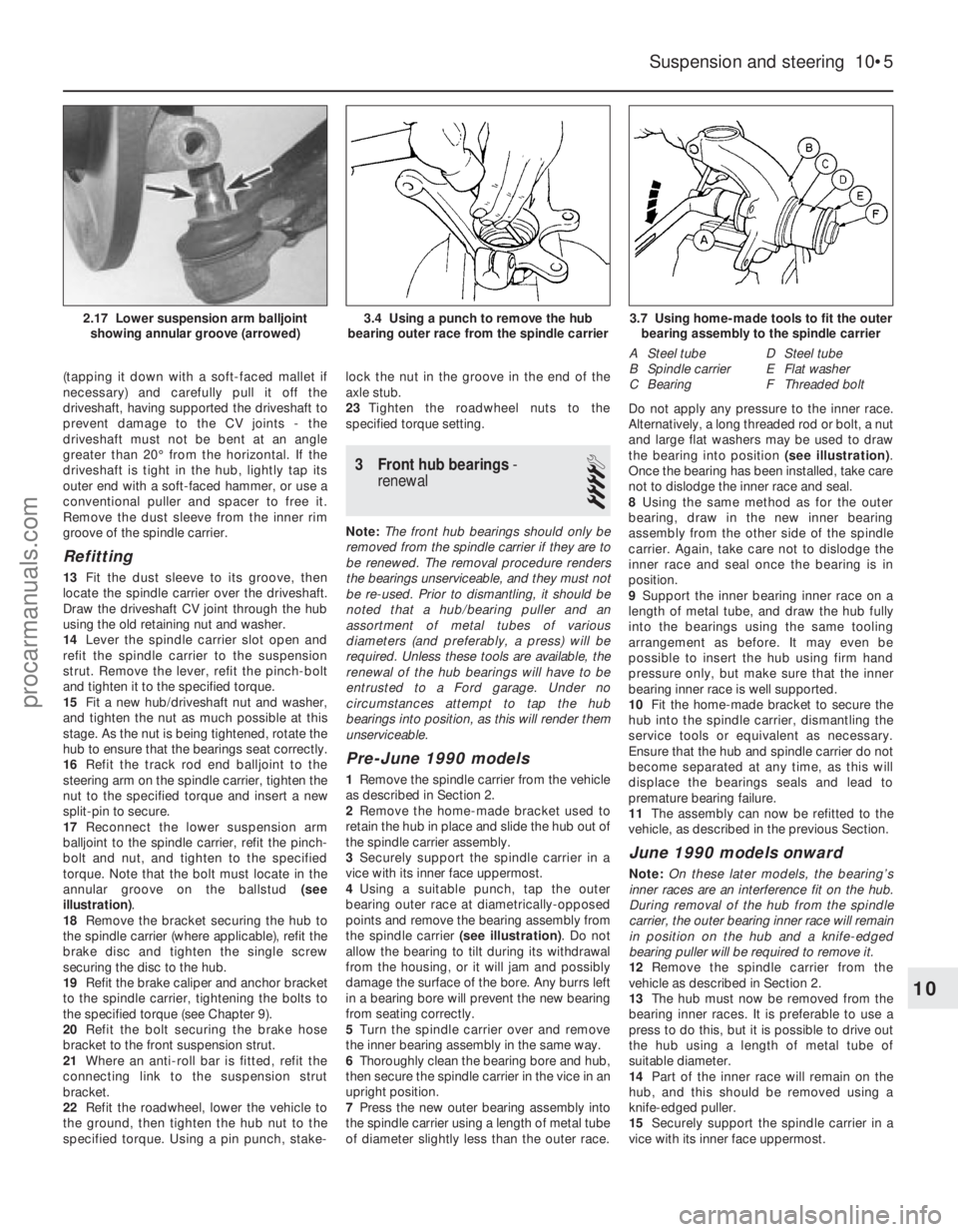
17 Reconnect the lower suspension arm
balljoint to the spindle carrier, refit the pinch-
bolt and nut, and tighten to the specified
torque. Note that the bolt must locate in the
annular groove on the ballstud (see
illustration) .
18 Remove the bracket securing the hub to
the spindle carrier (where applicable), refit the
brake disc and tighten the single screw
securing the disc to the hub.
19 Refit the brake caliper and anchor bracket
to the spindle carrier, tightening the bolts to
the specified torque (see Chapter 9).
20 Refit the bolt securing the brake hose
bracket to the front suspension strut.
21 Where an anti-roll bar is fitted, refit the
connecting link to the suspension strut
bracket.
22 Refit the roadwheel, lower the vehicle to
the ground, then tighten the hub nut to the
specified torque. Using a pin punch, stake- lock the nut in the groove in the end of the
axle stub.
23
Tighten the roadwheel nuts to the
specified torque setting.
3 Front hub bearings -
renewal
4
Note: The front hub bearings should only be
removed from the spindle carrier if they are to
be renewed. The removal procedure renders
the bearings unserviceable, and they must not
be re-used. Prior to dismantling, it should be
noted that a hub/bearing puller and an
assortment of metal tubes of various
diameters (and preferably, a press) will be
required. Unless these tools are available, the
renewal of the hub bearings will have to be
entrusted to a Ford garage. Under no
circumstances attempt to tap the hub
bearings into position, as this will render them
unserviceable.
Pre-June 1990 models
1 Remove the spindle carrier from the vehicle
as described in Section 2.
2 Remove the home-made bracket used to
retain the hub in place and slide the hub out of
the spindle carrier assembly.
3 Securely support the spindle carrier in a
vice with its inner face uppermost.
4 Using a suitable punch, tap the outer
bearing outer race at diametrically-opposed
points and remove the bearing assembly from
the spindle carrier (see illustration). Do not
allow the bearing to tilt during its withdrawal
from the housing, or it will jam and possibly
damage the surface of the bore. Any burrs left
in a bearing bore will prevent the new bearing
from seating correctly.
5 Turn the spindle carrier over and remove
the inner bearing assembly in the same way.
6 Thoroughly clean the bearing bore and hub,
then secure the spindle carrier in the vice in an
upright position.
7 Press the new outer bearing assembly into
the spindle carrier using a length of metal tube
of diameter slightly less than the outer race. Do not apply any pressure to the inner race.
Alternatively, a long threaded rod or bolt, a nut
and large flat washers may be used to draw
the bearing into position
(see illustration).
Once the bearing has been installed, take care
not to dislodge the inner race and seal.
8 Using the same method as for the outer
bearing, draw in the new inner bearing
assembly from the other side of the spindle
carrier. Again, take care not to dislodge the
inner race and seal once the bearing is in
position.
9 Support the inner bearing inner race on a
length of metal tube, and draw the hub fully
into the bearings using the same tooling
arrangement as before. It may even be
possible to insert the hub using firm hand
pressure only, but make sure that the inner
bearing inner race is well supported.
10 Fit the home-made bracket to secure the
hub into the spindle carrier, dismantling the
service tools or equivalent as necessary.
Ensure that the hub and spindle carrier do not
become separated at any time, as this will
displace the bearings seals and lead to
premature bearing failure.
11 The assembly can now be refitted to the
vehicle, as described in the previous Section.
June 1990 models onward
Note: On these later models, the bearing’s
inner races are an interference fit on the hub.
During removal of the hub from the spindle
carrier, the outer bearing inner race will remain
in position on the hub and a knife-edged
bearing puller will be required to remove it.
12 Remove the spindle carrier from the
vehicle as described in Section 2.
13 The hub must now be removed from the
bearing inner races. It is preferable to use a
press to do this, but it is possible to drive out
the hub using a length of metal tube of
suitable diameter.
14 Part of the inner race will remain on the
hub, and this should be removed using a
knife-edged puller.
15 Securely support the spindle carrier in a
vice with its inner face uppermost.
Suspension and steering 10•5
3.7 Using home-made tools to fit the outer bearing assembly to the spindle carrier
A Steel tube
B Spindle carrier
C Bearing D Steel tube
E Flat washer
F Threaded bolt
3.4 Using a punch to remove the hub
bearing outer race from the spindle carrier2.17 Lower suspension arm balljoint showing annular groove (arrowed)
10
1595Ford Fiesta Remakeprocarmanuals.com
http://vnx.su
Page 201 of 296
8 Front suspension lower arm- removal and refitting
3
Removal
1Chock the rear wheels then jack up the
front of the car and support it on axle stands
(see “Jacking and Vehicle Support” ). Remove
the appropriate front roadwheel.
2 Remove the one-piece undertray (where
fitted), by turning its bayonet-type fasteners.
3 If lower arm mounting brackets are to be
removed on XR2i models, remove the front
suspension crossmember as described in the
previous Section.
4 Unscrew and remove the lower arm
balljoint-to-spindle carrier pinch-bolt. Prise
the joint open using a large flat-bladed tool,
and detach the balljoint from the spindle
carrier. Take care not to damage the balljoint
seal during the separation procedures.
5 Where an anti-roll bar is fitted, undo the two
bolts and remove the clamp bracket.
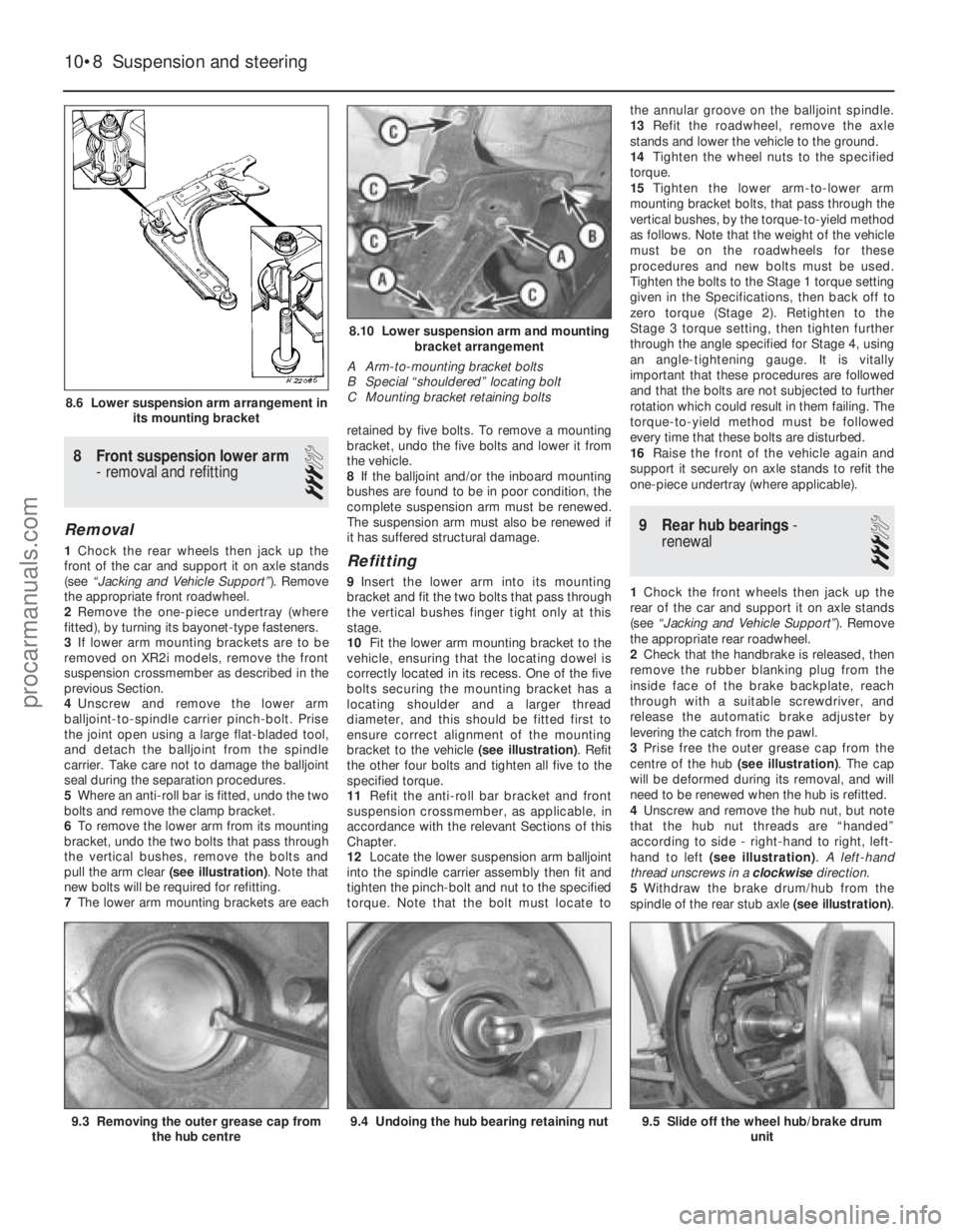
6 To remove the lower arm from its mounting
bracket, undo the two bolts that pass through
the vertical bushes, remove the bolts and
pull the arm clear (see illustration). Note that
new bolts will be required for refitting.
7 The lower arm mounting brackets are each retained by five bolts. To remove a mounting
bracket, undo the five bolts and lower it from
the vehicle.
8
If the balljoint and/or the inboard mounting
bushes are found to be in poor condition, the
complete suspension arm must be renewed.
The suspension arm must also be renewed if
it has suffered structural damage.Refitting
9 Insert the lower arm into its mounting
bracket and fit the two bolts that pass through
the vertical bushes finger tight only at this
stage.
10 Fit the lower arm mounting bracket to the
vehicle, ensuring that the locating dowel is
correctly located in its recess. One of the five
bolts securing the mounting bracket has a
locating shoulder and a larger thread
diameter, and this should be fitted first to
ensure correct alignment of the mounting
bracket to the vehicle (see illustration). Refit
the other four bolts and tighten all five to the
specified torque.
11 Refit the anti-roll bar bracket and front
suspension crossmember, as applicable, in
accordance with the relevant Sections of this
Chapter.
12 Locate the lower suspension arm balljoint
into the spindle carrier assembly then fit and
tighten the pinch-bolt and nut to the specified
torque. Note that the bolt must locate to the annular groove on the balljoint spindle.
13
Refit the roadwheel, remove the axle
stands and lower the vehicle to the ground.
14 Tighten the wheel nuts to the specified
torque.
15 Tighten the lower arm-to-lower arm
mounting bracket bolts, that pass through the
vertical bushes, by the torque-to-yield method
as follows. Note that the weight of the vehicle
must be on the roadwheels for these
procedures and new bolts must be used.
Tighten the bolts to the Stage 1 torque setting
given in the Specifications, then back off to
zero torque (Stage 2). Retighten to the
Stage 3 torque setting, then tighten further
through the angle specified for Stage 4, using
an angle-tightening gauge. It is vitally
important that these procedures are followed
and that the bolts are not subjected to further
rotation which could result in them failing. The
torque-to-yield method must be followed
every time that these bolts are disturbed.
16 Raise the front of the vehicle again and
support it securely on axle stands to refit the
one-piece undertray (where applicable).
9 Rear hub bearings -
renewal
3
1 Chock the front wheels then jack up the
rear of the car and support it on axle stands
(see “Jacking and Vehicle Support” ). Remove
the appropriate rear roadwheel.
2 Check that the handbrake is released, then
remove the rubber blanking plug from the
inside face of the brake backplate, reach
through with a suitable screwdriver, and
release the automatic brake adjuster by
levering the catch from the pawl.
3 Prise free the outer grease cap from the
centre of the hub (see illustration). The cap
will be deformed during its removal, and will
need to be renewed when the hub is refitted.
4 Unscrew and remove the hub nut, but note
that the hub nut threads are “handed”
according to side - right-hand to right, left-
hand to left (see illustration) . A left-hand
thread unscrews in a clockwisedirection.
5 Withdraw the brake drum/hub from the
spindle of the rear stub axle (see illustration).
10•8 Suspension and steering
9.5 Slide off the wheel hub/brake drum
unit9.4 Undoing the hub bearing retaining nut9.3 Removing the outer grease cap fromthe hub centre
8.10 Lower suspension arm and mountingbracket arrangement
A Arm-to-mounting bracket bolts
B Special “shouldered” locating bolt
C Mounting bracket retaining bolts
8.6 Lower suspension arm arrangement in its mounting bracket
1595Ford Fiesta Remakeprocarmanuals.com
http://vnx.su