roof FORD FIESTA 1989 Service User Guide
[x] Cancel search | Manufacturer: FORD, Model Year: 1989, Model line: FIESTA, Model: FORD FIESTA 1989Pages: 296, PDF Size: 10.65 MB
Page 212 of 296
11
1595Ford Fiesta Remake
Torque wrench settingsNmlbf ft
Front seat slide mechanism-to-floor mounting bolts . . . . . . . . . . . . . . . 25 to 32 18 to 24
Rear seat backrest hinge to backrest . . . . . . . . . . . . . . . . . . . . . . . . . . . 3.7 to 4.6 2.7 to 3.4
Rear seat backrest hinge to body . . . . . . . . . . . . . . . . . . . . . . . . . . . . . 21 to 25 15 to 18
Rear seat belt anchors and stalks to body . . . . . . . . . . . . . . . . . . . . . . . 25 to 45 18 to 34
Rear seat belt retractor assembly to body . . . . . . . . . . . . . . . . . . . . . . . 25 to 45 18 to 34
Front seat belt stalks to floorpan . . . . . . . . . . . . . . . . . . . . . . . . . . . . . . 25 to 45 18 to 34
Front seat belt lower anchor bolt to body . . . . . . . . . . . . . . . . . . . . . . . 25 to 45 18 to 34
Front seat belt lower anchor slide bar bolt to body . . . . . . . . . . . . . . . . 25 to 45 18 to 34
Front seat belt retractor to B-pillar bolt . . . . . . . . . . . . . . . . . . . . . . . . . 25 to 45 18 to 34
Front seat belt upper anchor bolt to B-pillar (non-adjustable type) . . . . 25 to 45 18 to 34
Front seat belt upper anchor adjuster plate-to-B-pillar bolts . . . . . . . . . 19 to 28 14 to 22
Front seat belt upper anchor bolt to adjuster slide . . . . . . . . . . . . . . . . 25 to 45 18 to 34
Bonnet hinge-to-bonnet bolts . . . . . . . . . . . . . . . . . . . . . . . . . . . . . . . . 8.5 to 12 6.5 to 9
Bonnet latch retaining bolts . . . . . . . . . . . . . . . . . . . . . . . . . . . . . . . . . . 8 to 12 6 to 9
Tailgate hinge-to-tailgate bolts . . . . . . . . . . . . . . . . . . . . . . . . . . . . . . . . 8.5 to 12 6.5 to 9
Tailgate latch retaining bolts . . . . . . . . . . . . . . . . . . . . . . . . . . . . . . . . . . 8 to 12 6 to 9
Rear door lower hinge cap bolts . . . . . . . . . . . . . . . . . . . . . . . . . . . . . . 8.5 to 12 6.5 to 9
Rear door latch retaining bolts . . . . . . . . . . . . . . . . . . . . . . . . . . . . . . . . 8.5 to 12 6.5 to 9
Front and rear bumper retaining nuts . . . . . . . . . . . . . . . . . . . . . . . . . . . 8 to 12 6 to 9
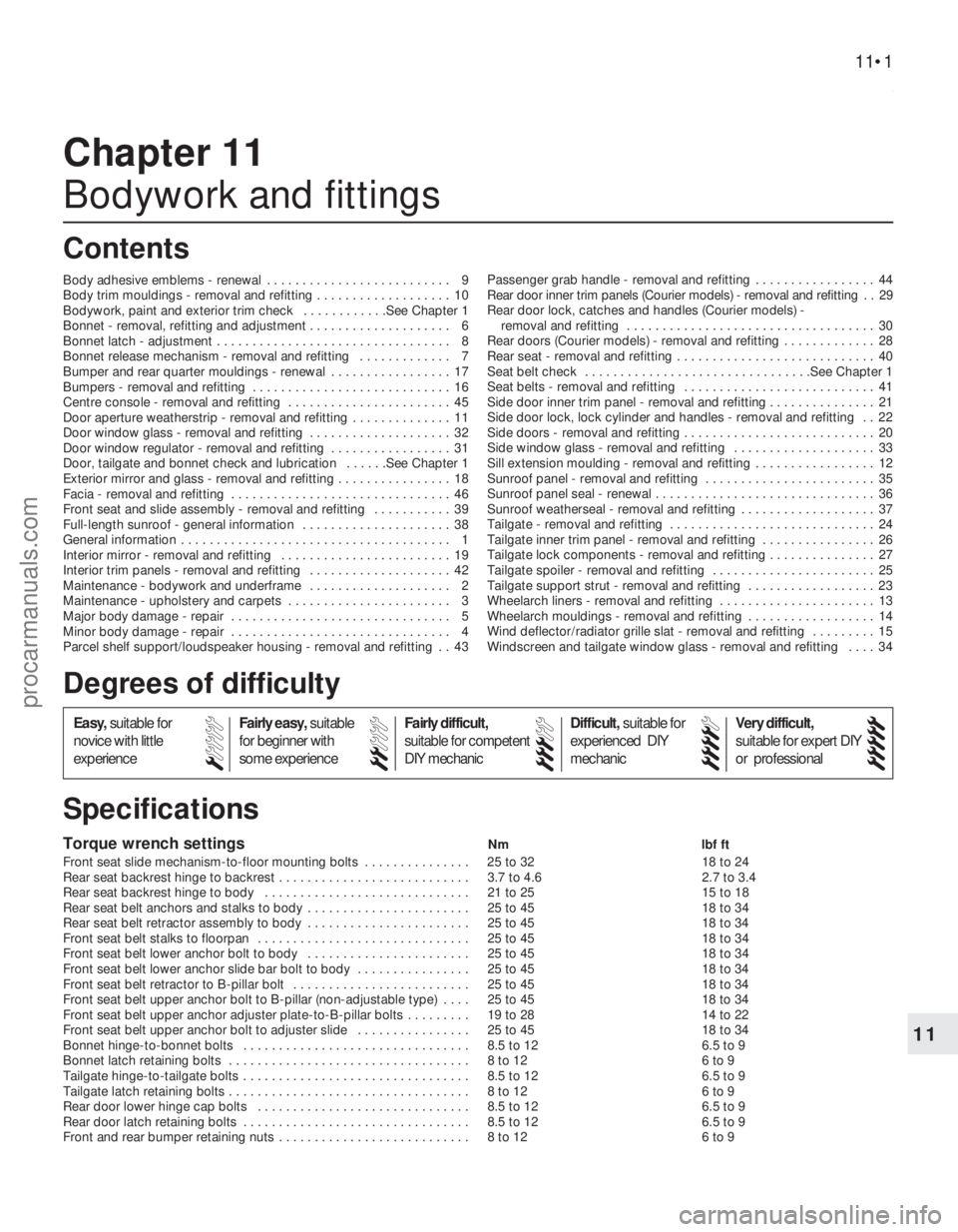
Chapter 11
Bodywork and fittings
Body adhesive emblems - renewal . . . . . . . . . . . . . . . . . . . . . . . . . . 9
Body trim mouldings - removal and refitting . . . . . . . . . . . . . . . . . . . 10
Bodywork, paint and exterior trim check . . . . . . . . . . . .See Chapter 1
Bonnet - removal, refitting and adjustment . . . . . . . . . . . . . . . . . . . . 6
Bonnet latch - adjustment . . . . . . . . . . . . . . . . . . . . . . . . . . . . . . . . . 8
Bonnet release mechanism - removal and refitting . . . . . . . . . . . . . 7
Bumper and rear quarter mouldings - renewal . . . . . . . . . . . . . . . . . 17
Bumpers - removal and refitting . . . . . . . . . . . . . . . . . . . . . . . . . . . . 16
Centre console - removal and refitting . . . . . . . . . . . . . . . . . . . . . . . 45
Door aperture weatherstrip - removal and refitting . . . . . . . . . . . . . . 11
Door window glass - removal and refitting . . . . . . . . . . . . . . . . . . . . 32
Door window regulator - removal and refitting . . . . . . . . . . . . . . . . . 31
Door, tailgate and bonnet check and lubrication . . . . . .See Chapter 1
Exterior mirror and glass - removal and refitting . . . . . . . . . . . . . . . . 18
Facia - removal and refitting . . . . . . . . . . . . . . . . . . . . . . . . . . . . . . . 46
Front seat and slide assembly - removal and refitting . . . . . . . . . . . 39
Full-length sunroof - general information . . . . . . . . . . . . . . . . . . . . . 38
General information . . . . . . . . . . . . . . . . . . . . . . . . . . . . . . . . . . . .\
. . 1
Interior mirror - removal and refitting . . . . . . . . . . . . . . . . . . . . . . . . 19
Interior trim panels - removal and refitting . . . . . . . . . . . . . . . . . . . . 42
Maintenance - bodywork and underframe . . . . . . . . . . . . . . . . . . . . 2
Maintenance - upholstery and carpets . . . . . . . . . . . . . . . . . . . . . . . 3
Major body damage - repair . . . . . . . . . . . . . . . . . . . . . . . . . . . . . . . 5
Minor body damage - repair . . . . . . . . . . . . . . . . . . . . . . . . . . . . . . . 4
Parcel shelf support/loudspeaker housing - removal and refitting . . 43 Passenger grab handle - removal and refitting . . . . . . . . . . . . . . . . . 44
Rear door inner trim panels (Courier models) - removal and refitting . . 29
Rear door lock, catches and handles (Courier models) -
removal and refitting . . . . . . . . . . . . . . . . . . . . . . . . . . . . . . . . . . . 30
Rear doors (Courier models) - removal and refitting . . . . . . . . . . . . . 28
Rear seat - removal and refitting . . . . . . . . . . . . . . . . . . . . . . . . . . . . 40
Seat belt check . . . . . . . . . . . . . . . . . . . . . . . . . . . . . . . .See Chap\
ter 1
Seat belts - removal and refitting . . . . . . . . . . . . . . . . . . . . . . . . . . . 41
Side door inner trim panel - removal and refitting . . . . . . . . . . .\
. . . . 21
Side door lock, lock cylinder and handles - removal and refitting . . 22
Side doors - removal and refitting . . . . . . . . . . . . . . . . . . . . . . . . . . . 20
Side window glass - removal and refitting . . . . . . . . . . . . . . . . . . . . 33
Sill extension moulding - removal and refitting . . . . . . . . . . . . . . . . . 12
Sunroof panel - removal and refitting . . . . . . . . . . . . . . . . . . . . . . . . 35
Sunroof panel seal - renewal . . . . . . . . . . . . . . . . . . . . . . . . . . . . . . . 36
Sunroof weatherseal - removal and refitting . . . . . . . . . . . . . . . . . . . 37
Tailgate - removal and refitting . . . . . . . . . . . . . . . . . . . . . . . . . . . . . 24
Tailgate inner trim panel - removal and refitting . . . . . . . . . . . . . . . . 26
Tailgate lock components - removal and refitting . . . . . . . . . . . . . . . 27
Tailgate spoiler - removal and refitting . . . . . . . . . . . . . . . . . . . . . . . 25
Tailgate support strut - removal and refitting . . . . . . . . . . . . . . . . . . 23
Wheelarch liners - removal and refitting . . . . . . . . . . . . . . . . . . . . . . 13
Wheelarch mouldings - removal and refitting . . . . . . . . . . . . . . . . . . 14
Wind deflector/radiator grille slat - removal and refitting . . . . . . . . . 15
Windscreen and tailgate window glass - removal and refitting . . . . 34
11•1
Specifications Contents
Easy, suitable for
novice with little
experience Fairly easy,
suitable
for beginner with
some experience Fairly difficult,
suitable for competent
DIY mechanic
Difficult,
suitable for
experienced DIY
mechanic Very difficult,
suitable for expert DIY
or professional
Degrees of difficulty
54321
procarmanuals.com
http://vnx.su
Page 216 of 296
4Pull the latch end of the cable into the
engine compartment, noting cable routing and
clips fitted. Remove the cable from its clips.
5 Detach the cable from its release lever on
the steering column, by aligning the cable
core with the slot on the release lever and
withdrawing the end fixing. Detach the cable
from its outer core abutment on the steering
column lock housing.
6 Unclip the cable from its pedal box
location, then detach the bulkhead grommet
and pass the cable through into the engine
compartment. Withdraw the cable from the
vehicle.
7 The release lever on the steering column
may be removed, if required, by unhooking
the spring from its retaining arms, then
disengaging its retaining arms from the
steering column lock housing.
Refitting
8 Refit the release lever, if removed, by
reversing the method of removal.
9 To install the release cable, first pass the
latch end of the cable down the right-hand
side of the steering column, through its
bulkhead location, and out into the engine
compartment.
10 Fit the cable to its clip on the pedal box
assembly, then reconnect the cable to the
release lever and the steering column lock
housing abutment by reversing the method of
removal.
11 Where applicable, refit the choke warning
light switch/pull control assembly, to the lower steering column shroud, by reversing the
method of removal. Refit the shroud.
12
Seat the release cable grommet into the
bulkhead.
13 Route and secure the release cable in the
engine compartment.
14 Reconnect the release cable to the latch,
then refit the latch to the body, setting the
latch at its maximum height position, and
tightening only the bottom retaining screw.
15 Adjust the latch for flush bonnet closure in
accordance with Section 8.
8 Bonnet latch - adjustment
1
1To adjust the bonnet latch, remove the two
upper latch retaining screws, then with the
latch raised to its maximum height position
and secured with the lower retaining screw,
close the bonnet.
2 Slacken the lower latch retaining screw,
through the gap between the leading edge of
the bonnet and the radiator grille slot, then
set the bonnet so it sits flush with its
surrounding panels - it may be necessary to
adjust the height of the bump stops (see
Section 6) if they have been moved in any
way, or if fitting a new bonnet.
3 With the desired bonnet closure obtained,
fully tighten the lower latch retaining screw,
then open the bonnet and refit the two upper
latch retaining screws, tightening to the
specified torque.
9 Body adhesive emblems -
renewal
1
1 Using a length of strong thin diameter cord
(fishing line is ideal), break the adhesive bond
between the emblem and the panel.
2 Thoroughly clean all traces of the old
adhesive from the emblem location, using
methylated spirit, taking all normal safety
precautions. Allow the emblem location to
dry.
3 Gently heat the new emblem until it is warm
to the touch. 4
Peel the protective backing paper from the
emblem then, taking care not to touch the
adhesive, position the emblem on the panel.
Maintain hand pressure evenly for at least
thirty seconds to ensure a good bond.
10 Body trim mouldings -
removal and refitting
1
Roof drip rail moulding (all
models except Courier)
Removal
1 Remove the drip rail moulding by gently
raising the forward end from its retaining
flange, taking care not to bend or kink it, then
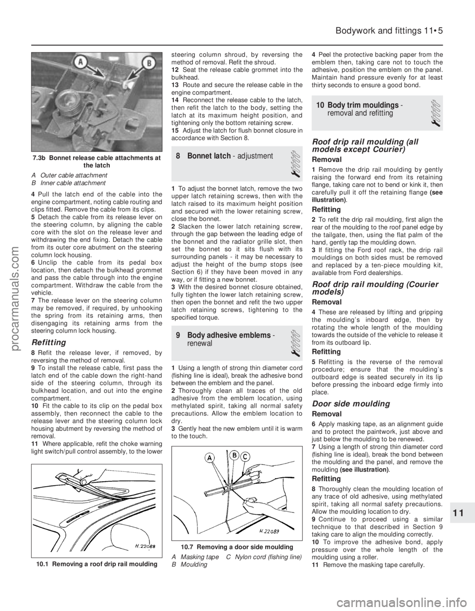
carefully pull it off the retaining flange (see
illustration) .
Refitting
2To refit the drip rail moulding, first align the
rear of the moulding to the roof panel edge by
the tailgate, then, using the flat palm of the
hand, gently tap the moulding down.
3 If fitting the Ford roof rack, the drip rail
mouldings on both sides must be removed
and replaced by a ten-piece moulding kit,
available from Ford dealerships.
Roof drip rail moulding (Courier
models)
Removal
4 These are released by lifting and gripping
the moulding’s inboard edge, then by
rotating the whole length of the moulding
towards the outside of the vehicle to release it
from its outboard lip.
Refitting
5 Refitting is the reverse of the removal
procedure; ensure that the moulding’s
outboard edge is seated securely in its lip
before pressing the inboard edge firmly into
place.
Door side moulding
Removal
6 Apply masking tape, as an alignment guide
and to protect the paintwork, just above and
just below the moulding to be renewed.
7 Using a length of strong thin diameter cord
(fishing line is ideal), break the bond between
the moulding and the panel, and remove the
moulding (see illustration) .
Refitting
8Thoroughly clean the moulding location of
any trace of old adhesive, using methylated
spirit, taking all normal safety precautions.
Allow the moulding location to dry.
9 Continue to proceed using a similar
technique to that described in Section 9
taking care to align the moulding correctly.
10 To improve the adhesive bond, apply
pressure over the whole length of the
moulding using a roller.
11 Remove the masking tape carefully.
Bodywork and fittings 11•5
7.3b Bonnet release cable attachments at
the latch
A Outer cable attachment
B Inner cable attachment
10.7 Removing a door side moulding
A Masking tape C Nylon cord (fishing line)
B Moulding
10.1 Removing a roof drip rail moulding
11
1595Ford Fiesta Remakeprocarmanuals.com
http://vnx.su
Page 227 of 296
suitable adhesive; it is recommended that this
task be left to a Ford dealer or similar expert.
15To remove the window glass, remove their
retaining screws and withdraw the lock
assemblies, slide the front glass as far to the
rear as possible, then prise up and withdraw
the front glass guide; it will be necessary to
pull the last part of the guide from under the
glass.
16 Withdraw the vertical seal and two
support blocks from between the two glasses,
slide the seal to the front of the frame, and
withdraw it. Slide each glass in turn
to the front of the frame and withdraw it,
then prise up and withdraw the rear glass
guide.
Refitting
17 On refitting, check that the glass guides
are undamaged; renew them if necessary.
Ensure that the lock assemblies are removed
from both glasses.
18 Press the rear glass guide into place. Refit
first the rear glass, fitting it to the front of the
frame and sliding it to the rear, then the front
glass, in the same way.
19 To refit the vertical seal, sandwich it
between two strips of thin sheet metal and
install it, with its support blocks, first in the
front part of the frame, then push it into place.
This will require some effort as the glass is
reached, due to the distortion caused by the
location notch on the block. When the seal is
fully in place, withdraw the metal strips, and
check that the seal’s lips have not folded back
on themselves.
20 When refitting the front glass guide, locate
it first around the frame’s detent catch, then
slide it under the glass using soapy water as a
lubricant.
21 Refit the lock assemblies, clean the
glasses, and check the operation of the
windows and locks.
34 Windscreen and tailgate window glass -
removal and refitting
4
Note : The DIY mechanic is advised to leave
windscreen/tailgate window glass removal
and refitting to an expert. For those with the
necessary tools and equipment, the
following paragraphs are a guide to the
procedure.
Removal
1 Remove the windscreen/tailgate wiper arms
as described in Chapter 12.
2 If removing the windscreen, remove both A-
pillar trims, and release the front of the
headlining by removing the sun visors and
courtesy light. If a heated windscreen is fitted,
disconnect its electrical contacts at the
windscreen. If removing the tailgate window
glass, disconnect the wiring to the heating
element. 3
As a precautionary measure to prevent
damage to the paintwork, cover the
surrounding bodywork with an old blanket or
similar.
4 Using a suitable tool, release the
weatherseal from the top and sides of the
body aperture flange before exerting pressure
from the inside of the vehicle to remove the
assembly. It is strongly advised that an
assistant outside the vehicle is ready to
receive the glass as it is pushed out.
5 With the assembly removed from the
vehicle, detach the weatherseal from the
windscreen/tailgate glass.
Refitting
6 With reference to the procedures described
for the fixed side window glass in Section 33,
clean the weatherseal, then refit in
accordance with the rest of that Section.
7 Any trim and equipment removed during
preparation should now be refitted.
35 Sunroof panel -
removal and refitting
1
Removal
1 Open the sunroof fully using the handwheel.
2 Detach the sunroof from its rearward
mounting point by pressing in the red locking
bar on the handwheel, then raise it and
remove.
Refitting
3 To refit, engage the hinges in their
locations, in the forward edge of the sunroof
opening, then lower the sunroof. Allow the
handwheel to click into its safety lock.
4 Check that the safety lock mechanism
retains the panel securely.
5 Close the sunroof fully using the
handwheel.
36 Sunroof panel seal -
renewal
1
1 Remove the sunroof panel, as described in
Section 35, then lay the panel on a soft cloth.
2 Remove the two hinge plate assemblies
from the panel by undoing the hinge plate
retaining screws.
3 Pull the seal from the panel edge, noting the
position of its join.
4 Starting from the position of the original
join, press the seal into position, ensuring that
it sits evenly right around. Adjust as necessary
so that the ends butt tightly together.
5 Refit the two hinge plate assemblies to the
panel.
6 Refit the sunroof panel, as described in
Section 35.
37 Sunroof weatherseal -
removal and refitting
1
Removal
1 Remove the sunroof panel, as described in
Section 35.
2 Starting from the joint on the rearward
opening edge, pull the seal up and remove.
Refitting
3 Refitting is a reversal of the removal
procedure, ensuring that the weatherseal
does not deform at the corners, or split at the
joint.
38 Full-length sunroof -
general information
1 The full-length sunroof is electrically-
operated, the operating system consisting of
the motor and the roof-mounted switch. The
circuit is fed via fuses 18 and 28 from the
ignition switch; switch illumination is via
fuse 6.
2 All components are mounted in the roof of
the passenger compartment, above the
headlining at the front of the vehicle.
3 To open the sunroof, press the switch
lightly on the upper side; to close it, check
first that the opening is completely
unobstructed, and press the switch on the
lower side.
4 Maintenance is confined to checking for
freedom of action and a snug fit when shut.
Check that the seals are in good clean
condition and not scratched or damaged.
5 Owners must note the following to ensure
that the maximum trouble-free life from this
feature:
a) It is normal for the motor to slow down as
the sunroof approaches full opening.
b) If the sunroof stops before it is fully
opened in cold weather, this may be due
to the material being too hard to fold
correctly; do not force the sunroof open if
this is suspected.
c) If the material does not fold correctly on
opening at any time, close the sunroof
again, correct the folds by hand, and try
again.
d) Never open or close the sunroof with the
vehicle travelling at more than 70 mph
(120 km/h), and never allow passengers to
travel standing up or with any part of their
bodies in the opening.
e) Ensure that any collected water, snow or ice is removed from the sunroof before
opening it. Check that the deflector is
clear of water, particularly after washing
the vehicle; sponge it dry if necessary.
f) Never place heavy objects on the sunroof or its surrounds.
g) The sunroof should be cleaned frequently
11•16 Bodywork and fittings
1595Ford Fiesta Remakeprocarmanuals.com
http://vnx.su
Page 228 of 296
to avoid the material being stained by dirt.
Use a sponge, soft brush or soft cloth and
a neutral detergent, rinsing with a gentle
flow of clean water from directly above
until all traces of dirt and detergent are
removed. Neveruse a high-pressure jet,
pressure washer or similar, and do not
aim the jet from a hose at the joints of the
sunroof with the body (or water will enter
the passenger compartment). Neveruse
alcohol, petrol, thinners or similar
products to clean the material.
h) If the vehicle is parked in heavy rain, or if it is parked outside for long periods, a
proprietary car cover or tarpaulin should
be used to protect the roof and body. Do
not leave the sunroof open for long
periods; the material will stiffen in its folds,
with a consequent risk of tearing when the
sunroof is eventually operated again.
6 If the system fails with the sunroof open, it
can be closed in emergency by switching off
the ignition, prising out the access plug in
front of the switch, and using the crank
provided to rotate the motor shaft clockwise
until the roof is closed.
7 If the switch is thought to be at fault, it can
be removed after first disconnecting the
battery negative (earth) lead (refer to Chap-
ter 5, Section 1) ; the switch can then be
eased from its housing until the wires can be
disconnected. Refitting is the reverse of the
removal procedure.
8 If any other failure or problem is
encountered, the general inaccessibility of the
system’s components means that servicing
and fault-finding is beyond the capabilities of
most owners; the vehicle should be taken to a
Ford dealer for attention.
39 Front seat and slide assembly -
removal and refitting
1
Removal
Warning: On vehicles fitted with
mechanical seat belt pre-
tensioning stalks, be careful
when handling the seat, as the
tensioning device (“grabber”) contains a
powerful spring, which could cause injury
if released in an uncontrolled fashion. The
tensioning mechanism should be
immobilised by inserting a safety “transit
clip” available from Ford parts stockists.
You are strongly advised to seek the
advice of a Ford dealer as to the correct
use of the “transit clip” and the safety
implications before proceeding.
1 On pre-1994 models, slide the seat fully
rearwards to expose the two front slide
assembly to floorpan bolts. Remove all four
bolts securing the slides to the floorpan, and
remove the seat from the vehicle.
2 On later models, pull off the trim cover from
the outer slide. 3
On vehicles fitted with mechanical seat belt
pre-tensioning stalks, fit the safety “transit
clip”.
4 Slide the seat fully rearwards, remove the
inner slide trim cover then unscrew and
remove the front slide assembly to floorpan
bolts.
5 Now slide the seat fully forward, and
unscrew the rear slide securing bolts each
side. Lift the seat and remove it from the
vehicle.
Refitting
6 Position the seat in the vehicle, and align
the slide assemblies with their mounting bolt
locations in the floorpan. Refit the front
securing bolts first, followed by the
rear securing bolts, to ensure that the seat
runs smoothly in its slide mechanism. Tighten
the bolts to the specified torque. On later
models, remove the “transit clip” (where
applicable) and refit the trim covers.
40 Rear seat -
removal and refitting
1
Backrest and catch
Removal
1 To remove the backrest, release the
backrest catch/catches, then fold the
backrest forwards.
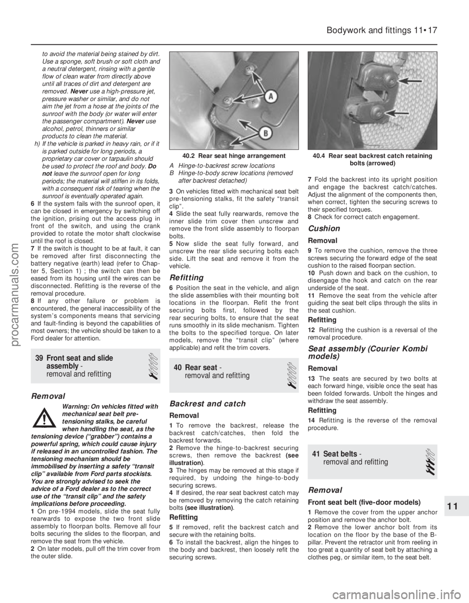
2 Remove the hinge-to-backrest securing
screws, then remove the backrest (see
illustration) .
3 The hinges may be removed at this stage if
required, by undoing the hinge-to-body
securing screws.
4 If desired, the rear seat backrest catch may
be removed by removing the catch retaining
bolts (see illustration) .
Refitting
5If removed, refit the backrest catch and
secure with the retaining bolts.
6 To install the backrest, align the hinges to
the body and backrest, then loosely refit the
securing screws. 7
Fold the backrest into its upright position
and engage the backrest catch/catches.
Adjust the alignment of the components then,
when correct, tighten the securing screws to
their specified torques.
8 Check for correct catch engagement.
Cushion
Removal
9To remove the cushion, remove the three
screws securing the forward edge of the seat
cushion to the raised floorpan section.
10 Push down and back on the cushion, to
disengage the hook and catch on the rear
underside of the seat.
11 Remove the seat from the vehicle after
guiding the seat belt clips through the slits in
the seat cushion.
Refitting
12 Refitting the cushion is a reversal of the
removal procedure.
Seat assembly (Courier Kombi
models)
Removal
13 The seats are secured by two bolts at
each forward hinge, visible once the seat has
been folded forwards. Unbolt the hinges and
withdraw the seat assembly.
Refitting
14 Refitting is the reverse of the removal
procedure.
41 Seat belts -
removal and refitting
3
Removal
Front seat belt (five-door models)
1 Remove the cover from the upper anchor
position and remove the anchor bolt.
2 Remove the lower anchor bolt from its
location on the floor by the base of the B-
pillar. Prevent the retractor unit from reeling in
too great a quantity of seat belt by attaching a
clothes peg, or similar item, to the seat belt.
Bodywork and fittings 11•17
40.4 Rear seat backrest catch retaining bolts (arrowed)40.2 Rear seat hinge arrangement
A Hinge-to-backrest screw locations
B Hinge-to-body screw locations (removed after backrest detached)
11
1595Ford Fiesta Remakeprocarmanuals.com
http://vnx.su
Page 235 of 296
 Circuit(s) protected
23 - . . . . . . . . . . . . . . . . . . . . . . . . . . . . . . . . . . . .\
. . . . . . . . . . . . . Unused
24/25 10")
Additional fuses behind main fuse board:
NoRating (amps) Circuit(s) protected
23 - . . . . . . . . . . . . . . . . . . . . . . . . . . . . . . . . . . . .\
. . . . . . . . . . . . . Unused
24/25 10 . . . . . . . . . . . . . . . . . . . . . . . . . . . . . . . . . . . .\
. . . . . . . . . . . . Rear fog lights
26 15 . . . . . . . . . . . . . . . . . . . . . . . . . . . . . . . . . . . .\
. . . . . . . . . . . . Tailgate remote release
27/28 30 . . . . . . . . . . . . . . . . . . . . . . . . . . . . . . . . . . . .\
. . . . . . . . . . . . Heated windscreen
Fuses - 1992 models onward
Main fuse board:
Fuses 1 to 22 . . . . . . . . . . . . . . . . . . . . . . . . . . . . . . . . . . . .\
. . . . . . . . . Unchanged from pre-1992 models
Additional fuses behind main fuse board:
No Rating (amps) Circuit(s) protected
23* - . . . . . . . . . . . . . . . . . . . . . . . . . . . . . . . . . . . .\
. . . . . . . . . . . . . . Unused
23** 10 . . . . . . . . . . . . . . . . . . . . . . . . . . . . . . . . . . . .\
. . . . . . . . . . . . Rear fog lights
24* - . . . . . . . . . . . . . . . . . . . . . . . . . . . . . . . . . . . .\
. . . . . . . . . . . . . . Unused 24** 10 . . . . . . . . . . . . . . . . . . . . . . . . . . . . . . . . . . . .\
. . . . . . . . . . . . Rear fog lights
25 15 . . . . . . . . . . . . . . . . . . . . . . . . . . . . . . . . . . . .\
. . . . . . . . . . . . Tailgate remote release, anti-theft warning system
26 30 . . . . . . . . . . . . . . . . . . . . . . . . . . . . . . . . . . . .\
. . . . . . . . . . . . Heated windscreen
27 30 . . . . . . . . . . . . . . . . . . . . . . . . . . . . . . . . . . . .\
. . . . . . . . . . . . Heated windscreen
28* 20 . . . . . . . . . . . . . . . . . . . . . . . . . . . . . . . . . . . .\
. . . . . . . . . . . . Full-length sunroof
28** 30 . . . . . . . . . . . . . . . . . . . . . . . . . . . . . . . . . . . .\
. . . . . . . . . . . . Automatic transmission starter inhibitor
29 10 . . . . . . . . . . . . . . . . . . . . . . . . . . . . . . . . . . . .\
. . . . . . . . . . . . Air bag
* Pre-1994 models
** 1994 models onward
Relays (pre-1992 models)
Note: Relay locations and circuits controlled are liable to change from year t\
o year. Consult a Ford dealer, for specific information.
No Circuit(s) controlled
I . . . . . . . . . . . . . . . . . . . . . . . . . . . . . . . . . . . .\
. . . . . . . . . . . . . . Heated rear window
II . . . . . . . . . . . . . . . . . . . . . . . . . . . . . . . . . . . .\
. . . . . . . . . . . . . . Windscreen wiper delay
III . . . . . . . . . . . . . . . . . . . . . . . . . . . . . . . . . . . .\
. . . . . . . . . . . . . . CFi (fuel injection) delay relay
IV . . . . . . . . . . . . . . . . . . . . . . . . . . . . . . . . . . . .\
. . . . . . . . . . . . . . Not used on UK models
V . . . . . . . . . . . . . . . . . . . . . . . . . . . . . . . . . . . .\
. . . . . . . . . . . . . . Ignition switch
VI . . . . . . . . . . . . . . . . . . . . . . . . . . . . . . . . . . . .\
. . . . . . . . . . . . . . Automatic transmission starter inhibitor/electric fuel pump (bridge fitted to carburettor engines without automatic transmission)
VII . . . . . . . . . . . . . . . . . . . . . . . . . . . . . . . . . . . .\
. . . . . . . . . . . . . . Headlight main beam
VIII . . . . . . . . . . . . . . . . . . . . . . . . . . . . . . . . . . . .\
. . . . . . . . . . . . . . Dim-dip lighting
IX . . . . . . . . . . . . . . . . . . . . . . . . . . . . . . . . . . . .\
. . . . . . . . . . . . . . Not used on UK models
X . . . . . . . . . . . . . . . . . . . . . . . . . . . . . . . . . . . .\
. . . . . . . . . . . . . . Not used on UK models
XI . . . . . . . . . . . . . . . . . . . . . . . . . . . . . . . . . . . .\
. . . . . . . . . . . . . . Heated windscreen
XII . . . . . . . . . . . . . . . . . . . . . . . . . . . . . . . . . . . .\
. . . . . . . . . . . . . . Anti-lock braking system
A . . . . . . . . . . . . . . . . . . . . . . . . . . . . . . . . . . . .\
. . . . . . . . . . . . . . Idle speed control (automatic transmission) two-tone horn (where fitt\
ed)
B . . . . . . . . . . . . . . . . . . . . . . . . . . . . . . . . . . . .\
. . . . . . . . . . . . . . Not used on UK models
C . . . . . . . . . . . . . . . . . . . . . . . . . . . . . . . . . . . .\
. . . . . . . . . . . . . . Front foglights (XR2i)
D . . . . . . . . . . . . . . . . . . . . . . . . . . . . . . . . . . . .\
. . . . . . . . . . . . . . Headlight dipped beam
E . . . . . . . . . . . . . . . . . . . . . . . . . . . . . . . . . . . .\
. . . . . . . . . . . . . . Dim-dip lighting
Relays (1992 models onward)
Note: Relay locations and circuits controlled are liable to change from year t\
o year. Consult a Ford dealer, for specific information.
No Circuit(s) controlled
I . . . . . . . . . . . . . . . . . . . . . . . . . . . . . . . . . . . .\
. . . . . . . . . . . . . . Heated rear window
II . . . . . . . . . . . . . . . . . . . . . . . . . . . . . . . . . . . .\
. . . . . . . . . . . . . . Windscreen wiper delay
III . . . . . . . . . . . . . . . . . . . . . . . . . . . . . . . . . . . .\
. . . . . . . . . . . . . . CFi delay relay or EFi supply relay (fuel injection)
IV . . . . . . . . . . . . . . . . . . . . . . . . . . . . . . . . . . . .\
. . . . . . . . . . . . . . Not used on UK models
V . . . . . . . . . . . . . . . . . . . . . . . . . . . . . . . . . . . .\
. . . . . . . . . . . . . . Ignition switch
VI . . . . . . . . . . . . . . . . . . . . . . . . . . . . . . . . . . . .\
. . . . . . . . . . . . . . Automatic transmission starter inhibitor, anti-theft warning system
VII . . . . . . . . . . . . . . . . . . . . . . . . . . . . . . . . . . . .\
. . . . . . . . . . . . . . Headlight main beam
VIII . . . . . . . . . . . . . . . . . . . . . . . . . . . . . . . . . . . .\
. . . . . . . . . . . . . . Anti-lock braking system and/or dim-dip lighting
IX . . . . . . . . . . . . . . . . . . . . . . . . . . . . . . . . . . . .\
. . . . . . . . . . . . . . Not used on UK models
X . . . . . . . . . . . . . . . . . . . . . . . . . . . . . . . . . . . .\
. . . . . . . . . . . . . . Not used on UK models
XI . . . . . . . . . . . . . . . . . . . . . . . . . . . . . . . . . . . .\
. . . . . . . . . . . . . . Heated windscreen
XII . . . . . . . . . . . . . . . . . . . . . . . . . . . . . . . . . . . .\
. . . . . . . . . . . . . . Anti-lock braking system
A . . . . . . . . . . . . . . . . . . . . . . . . . . . . . . . . . . . .\
. . . . . . . . . . . . . . Idle speed control (automatic transmission) or two-tone horn (where f\
itted)
B . . . . . . . . . . . . . . . . . . . . . . . . . . . . . . . . . . . .\
. . . . . . . . . . . . . . Fuel pump
C . . . . . . . . . . . . . . . . . . . . . . . . . . . . . . . . . . . .\
. . . . . . . . . . . . . . Front foglights (XR2i, RS Turbo and RS 1800)
D . . . . . . . . . . . . . . . . . . . . . . . . . . . . . . . . . . . .\
. . . . . . . . . . . . . . Headlight dipped beam
E . . . . . . . . . . . . . . . . . . . . . . . . . . . . . . . . . . . .\
. . . . . . . . . . . . . . Dim-dip lighting
F . . . . . . . . . . . . . . . . . . . . . . . . . . . . . . . . . . . .\
. . . . . . . . . . . . . . Not used on UK models
12•2 Body electrical systems
1595Ford Fiesta Remakeprocarmanuals.com
http://vnx.su
Page 248 of 296
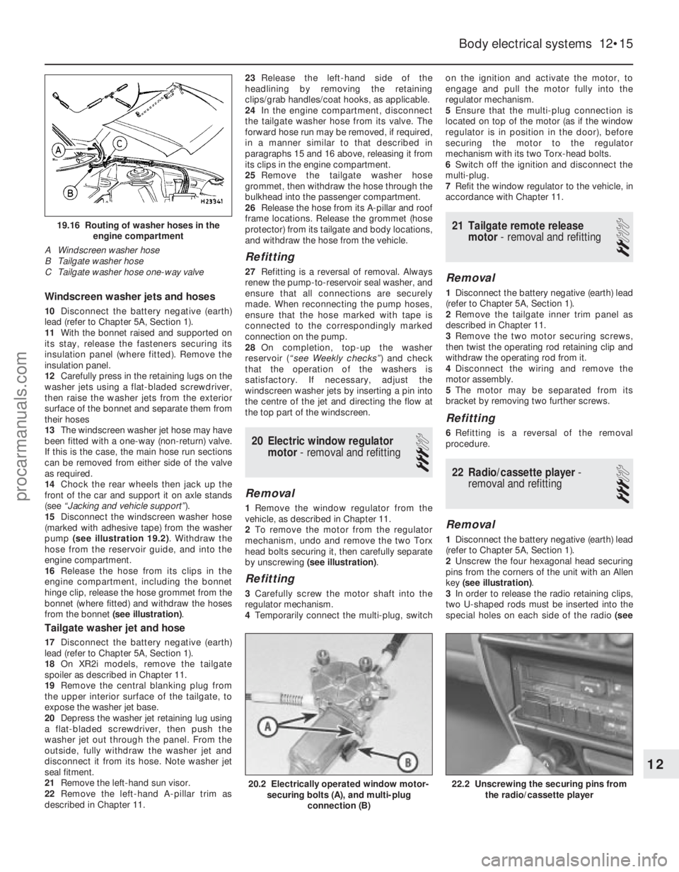
Windscreen washer jets and hoses
10Disconnect the battery negative (earth)
lead (refer to Chapter 5A, Section 1).
11 With the bonnet raised and supported on
its stay, release the fasteners securing its
insulation panel (where fitted). Remove the
insulation panel.
12 Carefully press in the retaining lugs on the
washer jets using a flat-bladed screwdriver,
then raise the washer jets from the exterior
surface of the bonnet and separate them from
their hoses
13 The windscreen washer jet hose may have
been fitted with a one-way (non-return) valve.
If this is the case, the main hose run sections
can be removed from either side of the valve
as required.
14 Chock the rear wheels then jack up the
front of the car and support it on axle stands
(see “Jacking and vehicle support” ).
15 Disconnect the windscreen washer hose
(marked with adhesive tape) from the washer
pump (see illustration 19.2) . Withdraw the
hose from the reservoir guide, and into the
engine compartment.
16 Release the hose from its clips in the
engine compartment, including the bonnet
hinge clip, release the hose grommet from the
bonnet (where fitted) and withdraw the hoses
from the bonnet (see illustration) .
Tailgate washer jet and hose
17Disconnect the battery negative (earth)
lead (refer to Chapter 5A, Section 1).
18 On XR2i models, remove the tailgate
spoiler as described in Chapter 11.
19 Remove the central blanking plug from
the upper interior surface of the tailgate, to
expose the washer jet base.
20 Depress the washer jet retaining lug using
a flat-bladed screwdriver, then push the
washer jet out through the panel. From the
outside, fully withdraw the washer jet and
disconnect it from its hose. Note washer jet
seal fitment.
21 Remove the left-hand sun visor.
22 Remove the left-hand A-pillar trim as
described in Chapter 11. 23
Release the left-hand side of the
headlining by removing the retaining
clips/grab handles/coat hooks, as applicable.
24 In the engine compartment, disconnect
the tailgate washer hose from its valve. The
forward hose run may be removed, if required,
in a manner similar to that described in
paragraphs 15 and 16 above, releasing it from
its clips in the engine compartment.
25 Remove the tailgate washer hose
grommet, then withdraw the hose through the
bulkhead into the passenger compartment.
26 Release the hose from its A-pillar and roof
frame locations. Release the grommet (hose
protector) from its tailgate and body locations,
and withdraw the hose from the vehicle.
Refitting
27 Refitting is a reversal of removal. Always
renew the pump-to-reservoir seal washer, and
ensure that all connections are securely
made. When reconnecting the pump hoses,
ensure that the hose marked with tape is
connected to the correspondingly marked
connection on the pump.
28 On completion, top-up the washer
reservoir ( “see Weekly checks” ) and check
that the operation of the washers is
satisfactory. If necessary, adjust the
windscreen washer jets by inserting a pin into
the centre of the jet and directing the flow at
the top part of the windscreen.
20 Electric window regulator motor - removal and refitting
3
Removal
1Remove the window regulator from the
vehicle, as described in Chapter 11.
2 To remove the motor from the regulator
mechanism, undo and remove the two Torx
head bolts securing it, then carefully separate
by unscrewing (see illustration) .
Refitting
3Carefully screw the motor shaft into the
regulator mechanism.
4 Temporarily connect the multi-plug, switch on the ignition and activate the motor, to
engage and pull the motor fully into the
regulator mechanism.
5
Ensure that the multi-plug connection is
located on top of the motor (as if the window
regulator is in position in the door), before
securing the motor to the regulator
mechanism with its two Torx-head bolts.
6 Switch off the ignition and disconnect the
multi-plug.
7 Refit the window regulator to the vehicle, in
accordance with Chapter 11.
21 Tailgate remote release motor - removal and refitting
2
Removal
1Disconnect the battery negative (earth) lead
(refer to Chapter 5A, Section 1).
2 Remove the tailgate inner trim panel as
described in Chapter 11.
3 Remove the two motor securing screws,
then twist the operating rod retaining clip and
withdraw the operating rod from it.
4 Disconnect the wiring and remove the
motor assembly.
5 The motor may be separated from its
bracket by removing two further screws.
Refitting
6 Refitting is a reversal of the removal
procedure.
22 Radio/cassette player -
removal and refitting
3
Removal
1 Disconnect the battery negative (earth) lead
(refer to Chapter 5A, Section 1).
2 Unscrew the four hexagonal head securing
pins from the corners of the unit with an Allen
key (see illustration) .
3 In order to release the radio retaining clips,
two U-shaped rods must be inserted into the
special holes on each side of the radio (see
Body electrical systems 12•15
19.16 Routing of washer hoses in the
engine compartment
A Windscreen washer hose
B Tailgate washer hose
C Tailgate washer hose one-way valve
22.2 Unscrewing the securing pins from the radio/cassette player20.2 Electrically operated window motor-securing bolts (A), and multi-plug
connection (B)
12
1595Ford Fiesta Remakeprocarmanuals.com
http://vnx.su
Page 249 of 296
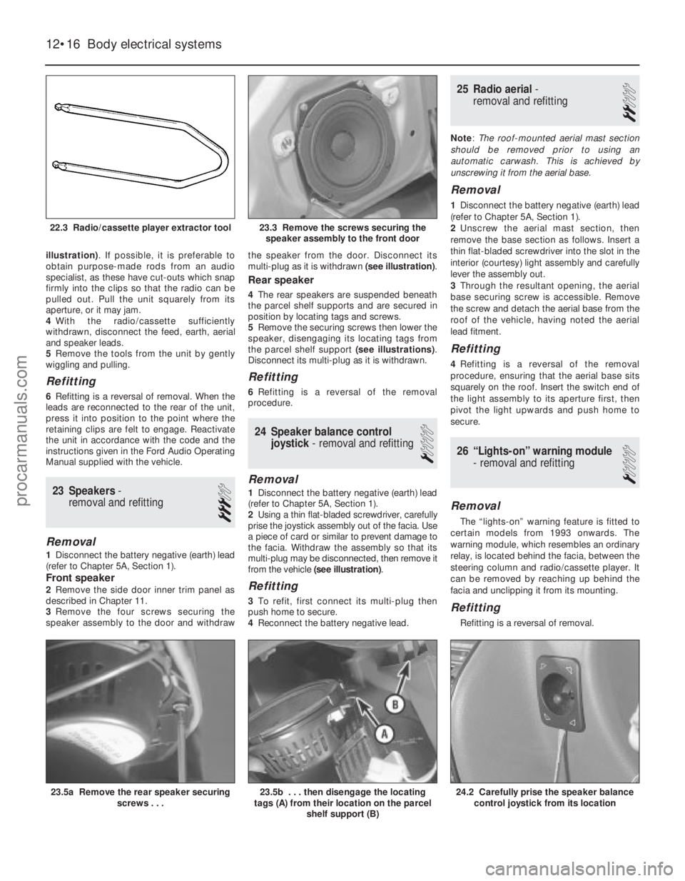
illustration). If possible, it is preferable to
obtain purpose-made rods from an audio
specialist, as these have cut-outs which snap
firmly into the clips so that the radio can be
pulled out. Pull the unit squarely from its
aperture, or it may jam.
4 With the radio/cassette sufficiently
withdrawn, disconnect the feed, earth, aerial
and speaker leads.
5 Remove the tools from the unit by gently
wiggling and pulling.
Refitting
6 Refitting is a reversal of removal. When the
leads are reconnected to the rear of the unit,
press it into position to the point where the
retaining clips are felt to engage. Reactivate
the unit in accordance with the code and the
instructions given in the Ford Audio Operating
Manual supplied with the vehicle.
23 Speakers -
removal and refitting
3
Removal
1 Disconnect the battery negative (earth) lead
(refer to Chapter 5A, Section 1).
Front speaker
2 Remove the side door inner trim panel as
described in Chapter 11.
3 Remove the four screws securing the
speaker assembly to the door and withdraw the speaker from the door. Disconnect its
multi-plug as it is withdrawn
(see illustration).
Rear speaker
4The rear speakers are suspended beneath
the parcel shelf supports and are secured in
position by locating tags and screws.
5 Remove the securing screws then lower the
speaker, disengaging its locating tags from
the parcel shelf support (see illustrations).
Disconnect its multi-plug as it is withdrawn.
Refitting
6 Refitting is a reversal of the removal
procedure.
24 Speaker balance control
joystick - removal and refitting
1
Removal
1Disconnect the battery negative (earth) lead
(refer to Chapter 5A, Section 1).
2 Using a thin flat-bladed screwdriver, carefully
prise the joystick assembly out of the facia. Use
a piece of card or similar to prevent damage to
the facia. Withdraw the assembly so that its
multi-plug may be disconnected, then remove it
from the vehicle (see illustration) .
Refitting
3To refit, first connect its multi-plug then
push home to secure.
4 Reconnect the battery negative lead.
25 Radio aerial -
removal and refitting
2
Note : The roof-mounted aerial mast section
should be removed prior to using an
automatic carwash. This is achieved by
unscrewing it from the aerial base.
Removal
1 Disconnect the battery negative (earth) lead
(refer to Chapter 5A, Section 1).
2 Unscrew the aerial mast section, then
remove the base section as follows. Insert a
thin flat-bladed screwdriver into the slot in the
interior (courtesy) light assembly and carefully
lever the assembly out.
3 Through the resultant opening, the aerial
base securing screw is accessible. Remove
the screw and detach the aerial base from the
roof of the vehicle, having noted the aerial
lead fitment.
Refitting
4 Refitting is a reversal of the removal
procedure, ensuring that the aerial base sits
squarely on the roof. Insert the switch end of
the light assembly to its aperture first, then
pivot the light upwards and push home to
secure.
26 “Lights-on” warning module
- removal and refitting
1
Removal
The “lights-on” warning feature is fitted to
certain models from 1993 onwards. The
warning module, which resembles an ordinary
relay, is located behind the facia, between the
steering column and radio/cassette player. It
can be removed by reaching up behind the
facia and unclipping it from its mounting.
Refitting
Refitting is a reversal of removal.
12•16 Body electrical systems
24.2 Carefully prise the speaker balance control joystick from its location23.5b . . . then disengage the locating
tags (A) from their location on the parcel
shelf support (B)23.5a Remove the rear speaker securing screws . . .
23.3 Remove the screws securing thespeaker assembly to the front door22.3 Radio/cassette player extractor tool
1595Ford Fiesta Remakeprocarmanuals.com
http://vnx.su
Page 268 of 296

1595 Ford Fiesta Remake
REF•2Conversion factors
Weights
Kerb weight*:3-door hatchback:1.0 litre models . . . . . . . . . . . . . . . . . . . . . . . . . . . . . . . . . . . .\
. . . . 770 to 780 kg
1.1 litre models . . . . . . . . . . . . . . . . . . . . . . . . . . . . . . . . . . . .\
. . . . 785 to 850 kg
1.3 litre models . . . . . . . . . . . . . . . . . . . . . . . . . . . . . . . . . . . .\
. . . . 825 to 870 kg
1.4 litre models . . . . . . . . . . . . . . . . . . . . . . . . . . . . . . . . . . . .\
. . . . 920 to 940 kg
1.6 litre models . . . . . . . . . . . . . . . . . . . . . . . . . . . . . . . . . . . .\
. . . . 990 to 1010 kg
XR2i (1.6 litre) models . . . . . . . . . . . . . . . . . . . . . . . . . . . . . . . . . . . 890 to 910 kg
XR2i (1.8 litre) models . . . . . . . . . . . . . . . . . . . . . . . . . . . . . . . . . . . 955 to 974 kg
RS Turbo models . . . . . . . . . . . . . . . . . . . . . . . . . . . . . . . . . . . .\
. . 910 to 930 kg
RS 1800 models . . . . . . . . . . . . . . . . . . . . . . . . . . . . . . . . . . . .\
. . . 954 to 965 kg
5-door hatchback: 1.0 litre models . . . . . . . . . . . . . . . . . . . . . . . . . . . . . . . . . . . .\
. . . . 795 to 810 kg
1.1 litre models . . . . . . . . . . . . . . . . . . . . . . . . . . . . . . . . . . . .\
. . . . 810 to 845 kg
1.3 litre models . . . . . . . . . . . . . . . . . . . . . . . . . . . . . . . . . . . .\
. . . . 845 to 870 kg
1.4 litre models . . . . . . . . . . . . . . . . . . . . . . . . . . . . . . . . . . . .\
. . . . 840 to 870 kg
1.6 litre models . . . . . . . . . . . . . . . . . . . . . . . . . . . . . . . . . . . .\
. . . . 980 to 1029 kg
Vans: 1.0 litre models . . . . . . . . . . . . . . . . . . . . . . . . . . . . . . . . . . . .\
. . . . 775 kg
1.1 litre models . . . . . . . . . . . . . . . . . . . . . . . . . . . . . . . . . . . .\
. . . . 775 to 790 kg
1.3 litre models . . . . . . . . . . . . . . . . . . . . . . . . . . . . . . . . . . . .\
. . . . 795 kg
Courier models . . . . . . . . . . . . . . . . . . . . . . . . . . . . . . . . . . . .\
. . . . 920 kg
Payload: 1.0 litre Van models . . . . . . . . . . . . . . . . . . . . . . . . . . . . . . . . . . . .\
310 to 335 kg
1.1 litre Van models . . . . . . . . . . . . . . . . . . . . . . . . . . . . . . . . . . . .\
310 to 335 kg1.3 litre Van models . . . . . . . . . . . . . . . . . . . . . . . . . . . . . . . . . . . .\
330 kgCourier models . . . . . . . . . . . . . . . . . . . . . . . . . . . . . . . . . . . .\
. . . . 515 to 525 kg
Maximum roof rack load . . . . . . . . . . . . . . . . . . . . . . . . . . . . . . . . . . . 75 kg
Maximum towing weight . . . . . . . . . . . . . . . . . . . . . . . . . . . . . . . . . . . Refer to your Ford dealer for weights and legal requirements concerning anticipated gradients and altitudes.
*Exact kerb weight varies depending on model - refer to VIN plate for de\
tails
procarmanuals.com
http://vnx.su
Page 270 of 296

1595 Ford Fiesta Remake
REF•4General repair procedures
Whenever servicing, repair or overhaul work
is carried out on the car or its components,
observe the following procedures and
instructions. This will assist in carrying out the
operation efficiently and to a professional
standar d of workmanship.
Joint mating faces and gaskets
When separating components at their
mating faces, never insert screwdrivers or
similar implements into the joint between the
faces in order to prise them apart. This can
cause severe damage which results in oil
leaks, coolant leaks, etc upon reassembly.
Separation is usually achieved by tapping
along the joint with a soft-faced hammer in
or der to break the seal. However, note that
this method may not be suitable where
dowels are used for component location.
Wher e a gasket is used between the mating
faces of two components, a new one must be
fitted on reassembly; fit it dry unless otherwise
stated in the repair procedure. Make sure that
the mating faces are clean and dry, with all
traces of old gasket removed. When cleaning a
joint face, use a tool which is unlikely to score
or damage the face, and remove any burrs or
nicks with an oilstone or fine file.
Make sure that tapped holes are cleaned
with a pipe cleaner, and keep them free of
jointing compound, if this is being used,
unless specifically instructed otherwise. Ensur e that all orifices, channels or pipes
ar e clear, and blow through them, preferably
using compressed air.
Oil seals
Oil seals can be removed by levering them
out with a wide flat-bladed screwdriver or
similar implement. Alternatively, a number of
self-tapping screws may be screwed into the
seal, and these used as a purchase for pliers or
some similar device in order to pull the seal free.
Whenever an oil seal is removed from its
working location, either individually or as part
of an assembly, it should be renewed. The very fine sealing lip of the seal is easily
damaged, and will not seal if the surface it
contacts is not completely clean and free fr om
scratches, nicks or grooves. If the original
sealing surface of the component cannot be
restor ed, and the manufacturer has not made
pr ovision for slight relocation of the seal
r elative to the sealing surface, the component
should be renewed.
Protect the lips of the seal from any surface
which may damage them in the course of
fitting. Use tape or a conical sleeve where
possible. Lubricate the seal lips with oil before
fitting and, on dual-lipped seals, fill the space
between the lips with grease.
Unless otherwise stated, oil seals must be
fitted with their sealing lips toward the
lubricant to be sealed.
Use a tubular drift or block of wood of the
appr opriate size to install the seal and, if the
seal housing is shouldered, drive the seal
down to the shoulder. If the seal housing is unshoulder
ed, the seal should be fitted with
its face flush with the housing top face (unless
otherwise instructed).
Screw threads and fastenings
Seized nuts, bolts and screws are quite a
common occurrence where corrosion has set
in, and the use of penetrating oil or releasing
fluid will often overcome this problem if the
of fending item is soaked for a while before
attempting to release it. The use of an impact
driver may also provide a means of releasing
such stubborn fastening devices, when used
in conjunction with the appropriate
scr ewdriver bit or socket. If none of these
methods works, it may be necessary to resort
to the careful application of heat, or the use of
a hacksaw or nut splitter device. Studs are usually removed by locking two
nuts together on the threaded part, and then
using a spanner on the lower nut to unscrew
the stud. Studs or bolts which have broken off
below the surface of the component in which
they are mounted can sometimes be removed
using a stud extractor. Always ensure that a
blind tapped hole is completely free from oil,
gr ease, water or other fluid before installing
the bolt or stud. Failure to do this could cause
the housing to crack due to the hydraulic
action of the bolt or stud as it is screwed in. When tightening a castellated nut to accept
a split pin, tighten the nut to the specified
tor que, where applicable, and then tighten
further to the next split pin hole. Never slacken
the nut to align the split pin hole, unless stated
in the repair procedure.
When checking or retightening a nut or bolt
to a specified torque setting, slacken the nut
or bolt by a quarter of a turn, and then
r etighten to the specified setting. However,
this should not be attempted where angular
tightening has been used. For some screw fastenings, notably
cylinder head bolts or nuts, torque wrench
settings are no longer specified for the latter
stages of tightening, “angle-tightening” being
called up instead. Typically, a fairly low torque wr ench setting will be applied to the
bolts/nuts in the correct sequence, followed
by one or more stages of tightening through
specified angles.
Locknuts, locktabs and washers
Any fastening which will rotate against a
component or housing during tightening
should always have a washer between it and
the relevant component or housing. Spring or split washers should always be
r enewed when they are used to lock a critical
component such as a big-end bearing
r etaining bolt or nut. Locktabs which are
folded over to retain a nut or bolt should
always be renewed.
Self-locking nuts can be re-used in non-
critical areas, providing resistance can be felt
when the locking portion passes over the bolt
or stud thread. However, it should be noted
that self-locking stiffnuts tend to lose their ef
fectiveness after long periods of use, and
should then be renewed as a matter of course.
Split pins must always be replaced with
new ones of the correct size for the hole. When thread-locking compound is found
on the threads of a fastener which is to be re-
used, it should be cleaned off with a wire
brush and solvent, and fresh compound
applied on reassembly.
Special tools
Some repair procedures in this manual
entail the use of special tools such as a press,
two or three-legged pullers, spring com-
pr essors, etc. Wherever possible, suitable
readily-available alternatives to the manu-
facturer’ s special tools are described, and are
shown in use. In some instances, where no
alter native is possible, it has been necessary
to resort to the use of a manufacturer’s tool, and this has been done for reasons of safety
as well as the efficient completion of the repair
operation. Unless you are highly-skilled and
have a thorough understanding of the
procedur es described, never attempt to
bypass the use of any special tool when the
pr ocedur e described specifies its use. Not
only is there a very great risk of personal
injury , but expensive damage could be
caused to the components involved.
Environmental considerations
When disposing of used engine oil, brake
fluid, antifreeze, etc, give due consideration to
any detrimental environmental effects. Do not,
for instance, pour any of the above liquids
down drains into the general sewage system,
or onto the ground to soak away. Many local
council refuse tips provide a facility for waste
oil disposal, as do some garages. If none of
these facilities are available, consult your local
Envir onmental Health Department, or the
National Rivers Authority, for further advice. With the universal tightening-up of legis-
lation regarding the emission of environmen-
tally-harmful substances from motor vehicles,
most vehicles have tamperproof devices fitted
to the main adjustment points of the fuel
system. These devices are primarily designed
to prevent unqualified persons from adjusting the fuel/air mixture, with the chance of a
consequent increase in toxic emissions. If
such devices are found during servicing or
overhaul, they should, wherever possible, be
r enewed or refitted in accordance with the
manufacturer’ s requirements or current
legislation.
Note: It is
antisocial and
illegal to dump
oil down the
drain. To find
the location of
your local oil
recycling
bank, call this
number free.
procarmanuals.com
http://vnx.su
Page 275 of 296
MImpact screwdriver
M Micrometer and/or vernier calipers (see
illustrations)
M Dial gauge (see illustration)
M Universal electrical multi-meter
M Cylinder compression gauge
(see illustration)
M Clutch plate alignment set (see
illustration)
M Brake shoe steady spring cup removal tool
(see illustration)
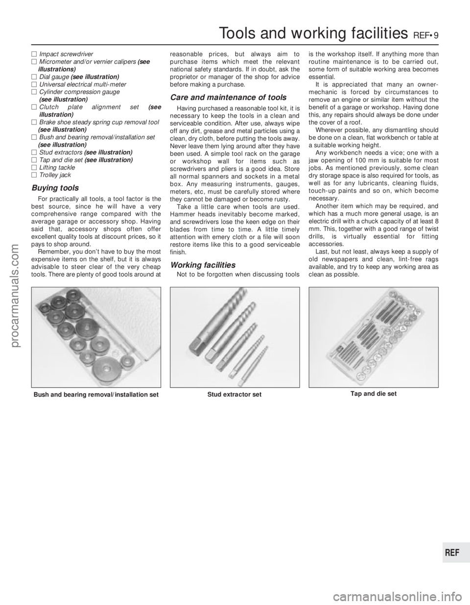
M Bush and bearing removal/installation set
(see illustration)
M Stud extractors (see illustration)
M Tap and die set (see illustration)
M Lifting tackle
M Trolley jack
Buying tools
For practically all tools, a tool factor is the
best source, since he will have a very
comprehensive range compared with the
average garage or accessory shop. Having
said that, accessory shops often offer
excellent quality tools at discount prices, so it
pays to shop around. Remember, you don’t have to buy the most
expensive items on the shelf, but it is always
advisable to steer clear of the very cheap
tools. There are plenty of good tools around at reasonable prices, but always aim to
purchase items which meet the relevant
national safety standards. If in doubt, ask the
proprietor or manager of the shop for advice
before making a purchase.
Care and maintenance of tools
Having purchased a reasonable tool kit, it is
necessary to keep the tools in a clean and
serviceable condition. After use, always wipe
off any dirt, grease and metal particles using a
clean, dry cloth, before putting the tools away.
Never leave them lying around after they have
been used. A simple tool rack on the garage
or workshop wall for items such as
screwdrivers and pliers is a good idea. Store
all normal spanners and sockets in a metal
box. Any measuring instruments, gauges,
meters, etc, must be carefully stored where
they cannot be damaged or become rusty. Take a little care when tools are used.
Hammer heads inevitably become marked,
and screwdrivers lose the keen edge on their
blades from time to time. A little timely
attention with emery cloth or a file will soon
restore items like this to a good serviceable
finish.
Working facilities
Not to be forgotten when discussing tools is the workshop itself. If anything more than
routine maintenance is to be carried out,
some form of suitable working area becomes
essential.
It is appreciated that many an owner-
mechanic is forced by circumstances to
remove an engine or similar item without the
benefit of a garage or workshop. Having done
this, any repairs should always be done under
the cover of a roof. Wherever possible, any dismantling should
be done on a clean, flat workbench or table at
a suitable working height. Any workbench needs a vice; one with a
jaw opening of 100 mm is suitable for most
jobs. As mentioned previously, some clean
dry storage space is also required for tools, as
well as for any lubricants, cleaning fluids,
touch-up paints and so on, which become
necessary.
Another item which may be required, and
which has a much more general usage, is an
electric drill with a chuck capacity of at least 8
mm. This, together with a good range of twist
drills, is virtually essential for fitting
accessories.
Last, but not least, always keep a supply of
old newspapers and clean, lint-free rags
available, and try to keep any working area as
clean as possible.
Bush and bearing removal/installation set Stud extractor setTap and die set
1595 Ford Fiesta Remake
Tools and working facilitiesREF•9
REF
procarmanuals.com
http://vnx.su