interior lights FORD FIESTA 1989 Service Repair Manual
[x] Cancel search | Manufacturer: FORD, Model Year: 1989, Model line: FIESTA, Model: FORD FIESTA 1989Pages: 296, PDF Size: 10.65 MB
Page 234 of 296
12
1595Ford Fiesta Remake
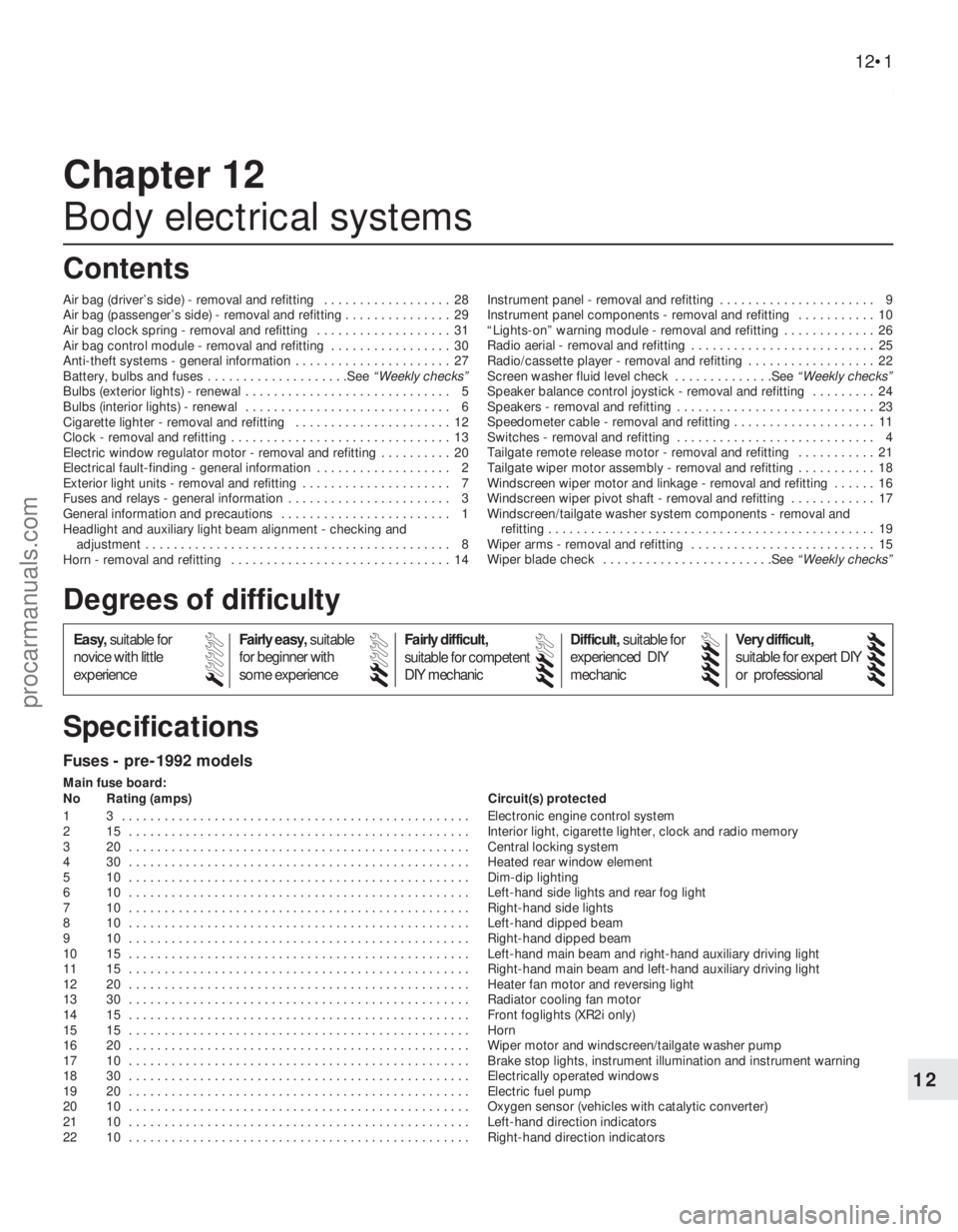
Fuses - pre-1992 models
Main fuse board:
No Rating (amps) Circuit(s) protected
1 3 . . . . . . . . . . . . . . . . . . . . . . . . . . . . . . . . . . . .\
. . . . . . . . . . . . . Electronic engine control system
2 15 . . . . . . . . . . . . . . . . . . . . . . . . . . . . . . . . . . . .\
. . . . . . . . . . . . Interior light, cigarette lighter, clock and radio memory
3 20 . . . . . . . . . . . . . . . . . . . . . . . . . . . . . . . . . . . .\
. . . . . . . . . . . . Central locking system
4 30 . . . . . . . . . . . . . . . . . . . . . . . . . . . . . . . . . . . .\
. . . . . . . . . . . . Heated rear window element
5 10 . . . . . . . . . . . . . . . . . . . . . . . . . . . . . . . . . . . .\
. . . . . . . . . . . . Dim-dip lighting
6 10 . . . . . . . . . . . . . . . . . . . . . . . . . . . . . . . . . . . .\
. . . . . . . . . . . . Left-hand side lights and rear fog light
7 10 . . . . . . . . . . . . . . . . . . . . . . . . . . . . . . . . . . . .\
. . . . . . . . . . . . Right-hand side lights
8 10 . . . . . . . . . . . . . . . . . . . . . . . . . . . . . . . . . . . .\
. . . . . . . . . . . . Left-hand dipped beam
9 10 . . . . . . . . . . . . . . . . . . . . . . . . . . . . . . . . . . . .\
. . . . . . . . . . . . Right-hand dipped beam
10 15 . . . . . . . . . . . . . . . . . . . . . . . . . . . . . . . . . . . .\
. . . . . . . . . . . . Left-hand main beam and right-hand auxiliary driving light
11 15 . . . . . . . . . . . . . . . . . . . . . . . . . . . . . . . . . . . .\
. . . . . . . . . . . . Right-hand main beam and left-hand auxiliary driving light
12 20 . . . . . . . . . . . . . . . . . . . . . . . . . . . . . . . . . . . .\
. . . . . . . . . . . . Heater fan motor and reversing light
13 30 . . . . . . . . . . . . . . . . . . . . . . . . . . . . . . . . . . . .\
. . . . . . . . . . . . Radiator cooling fan motor
14 15 . . . . . . . . . . . . . . . . . . . . . . . . . . . . . . . . . . . .\
. . . . . . . . . . . . Front foglights (XR2i only)
15 15 . . . . . . . . . . . . . . . . . . . . . . . . . . . . . . . . . . . .\
. . . . . . . . . . . . Horn
16 20 . . . . . . . . . . . . . . . . . . . . . . . . . . . . . . . . . . . .\
. . . . . . . . . . . . Wiper motor and windscreen/tailgate washer pump
17 10 . . . . . . . . . . . . . . . . . . . . . . . . . . . . . . . . . . . .\
. . . . . . . . . . . . Brake stop lights, instrument illumination and instrument warning
18 30 . . . . . . . . . . . . . . . . . . . . . . . . . . . . . . . . . . . .\
. . . . . . . . . . . . Electrically operated windows
19 20 . . . . . . . . . . . . . . . . . . . . . . . . . . . . . . . . . . . .\
. . . . . . . . . . . . Electric fuel pump
20 10 . . . . . . . . . . . . . . . . . . . . . . . . . . . . . . . . . . . .\
. . . . . . . . . . . . Oxygen sensor (vehicles with catalytic converter)
21 10 . . . . . . . . . . . . . . . . . . . . . . . . . . . . . . . . . . . .\
. . . . . . . . . . . . Left-hand direction indicators
22 10 . . . . . . . . . . . . . . . . . . . . . . . . . . . . . . . . . . . .\
. . . . . . . . . . . . Right-hand direction indicators
Chapter 12
Body electrical systems
Air bag (driver’s side) - removal and refitting . . . . . . . . . . . . . . . . . . 28
Air bag (passenger’s side) - removal and refitting . . . . . . . . \
. . . . . . . 29
Air bag clock spring - removal and refitting . . . . . . . . . . . . . . . . . . . 31
Air bag control module - removal and refitting . . . . . . . . . . . . . . . . . 30
Anti-theft systems - general information . . . . . . . . . . . . . . . . . . . . . . 27
Battery, bulbs and fuses . . . . . . . . . . . . . . . . . . . .See
“Weekly checks”
Bulbs (exterior lights) - renewal . . . . . . . . . . . . . . . . . . . . . . . . . . . . . 5
Bulbs (interior lights) - renewal . . . . . . . . . . . . . . . . . . . . . . . . . . . . . 6
Cigarette lighter - removal and refitting . . . . . . . . . . . . . . . . . . . . . . 12
Clock - removal and refitting . . . . . . . . . . . . . . . . . . . . . . . . . . . . . . . 13
Electric window regulator motor - removal and refitting . . . . . . . . . . 20
Electrical fault-finding - general information . . . . . . . . . . . . . . . . . . . 2
Exterior light units - removal and refitting . . . . . . . . . . . . . . . . . . . . . 7
Fuses and relays - general information . . . . . . . . . . . . . . . . . . . . . . . 3
General information and precautions . . . . . . . . . . . . . . . . . . . . . . . . 1
Headlight and auxiliary light beam alignment - checking and
adjustment . . . . . . . . . . . . . . . . . . . . . . . . . . . . . . . . . . . .\
. . . . . . . 8
Horn - removal and refitting . . . . . . . . . . . . . . . . . . . . . . . . . . . . . . . 14 Instrument panel - removal and refitting . . . . . . . . . . . . . . . . . . . . . . 9
Instrument panel components - removal and refitting . . . . . . . . . . . 10
“Lights-on” warning module - removal and refitting . . . . . . . . . . . . . 26
Radio aerial - removal and refitting . . . . . . . . . . . . . . . . . . . . . . . . . . 25
Radio/cassette player - removal and refitting . . . . . . . . . . . . . . . . . . 22
Screen washer fluid level check . . . . . . . . . . . . . .See
“Weekly checks”
Speaker balance control joystick - removal and refitting . . . . . . . . . 24
Speakers - removal and refitting . . . . . . . . . . . . . . . . . . . . . . . . . . . . 23
Speedometer cable - removal and refitting . . . . . . . . . . . . . . . . . . . . 11
Switches - removal and refitting . . . . . . . . . . . . . . . . . . . . . . . . . . . . 4
Tailgate remote release motor - removal and refitting . . . . . . . . . . . 21
Tailgate wiper motor assembly - removal and refitting . . . . . . . . . . . 18
Windscreen wiper motor and linkage - removal and refitting . . . . . . 16
Windscreen wiper pivot shaft - removal and refitting . . . . . . . . . . . . 17
Windscreen/tailgate washer system components - removal and refitting . . . . . . . . . . . . . . . . . . . . . . . . . . . . . . . . . . . .\
. . . . . . . . . . 19
Wiper arms - removal and refitting . . . . . . . . . . . . . . . . . . . . . . . . . . 15
Wiper blade check . . . . . . . . . . . . . . . . . . . . . . . .See “Weekly checks”
12•1
Specifications Contents
Easy,suitable for
novice with little
experience Fairly easy,
suitable
for beginner with
some experience Fairly difficult,
suitable for competent
DIY mechanic
Difficult,
suitable for
experienced DIY
mechanic Very difficult,
suitable for expert DIY
or professional
Degrees of difficulty
54321
procarmanuals.com
http://vnx.su
Page 236 of 296
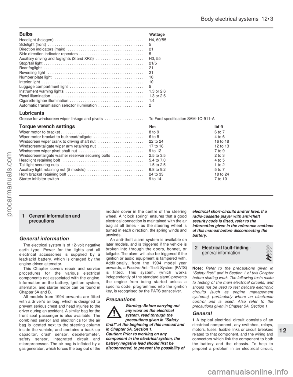
BulbsWattage
Headlight (halogen) . . . . . . . . . . . . . . . . . . . . . . . . . . . . . . . . . . . .\
. . . . . H4, 60/55
Sidelight (front) . . . . . . . . . . . . . . . . . . . . . . . . . . . . . . . . . . . .\
. . . . . . . . 5
Direction indicators (main) . . . . . . . . . . . . . . . . . . . . . . . . . . . . . . . . . . . 21
Side direction indicator repeaters . . . . . . . . . . . . . . . . . . . . . . . . . . . . . . 5
Auxiliary driving and foglights (S and XR2i) . . . . . . . . . . . . . . . . . . . . . . H3, 55
Stop/tail light . . . . . . . . . . . . . . . . . . . . . . . . . . . . . . . . . . . .\
. . . . . . . . . . 21/5
Rear foglight . . . . . . . . . . . . . . . . . . . . . . . . . . . . . . . . . . . .\
. . . . . . . . . . 21
Reversing light . . . . . . . . . . . . . . . . . . . . . . . . . . . . . . . . . . . .\
. . . . . . . . 21
Number plate light . . . . . . . . . . . . . . . . . . . . . . . . . . . . . . . . . . . .\
. . . . . 10
Interior light . . . . . . . . . . . . . . . . . . . . . . . . . . . . . . . . . . . .\
. . . . . . . . . . . 10
Luggage compartment light . . . . . . . . . . . . . . . . . . . . . . . . . . . . . . . . . . 5
Instrument warning lights . . . . . . . . . . . . . . . . . . . . . . . . . . . . . . . . . . . .\
1.3 or 2.6
Panel illumination . . . . . . . . . . . . . . . . . . . . . . . . . . . . . . . . . . . .\
. . . . . . 1.3 or 2.6
Cigarette lighter illumination . . . . . . . . . . . . . . . . . . . . . . . . . . . . . . . . . . 1.4
Automatic transmission selector illumination . . . . . . . . . . . . . . . . . . . . . 2
Lubricants
Grease for windscreen wiper linkage and pivots . . . . . . . . . . . . . . . . . . To Ford specification SAM-1C-911-A
Torque wrench settingsNm lbf ft
Wiper motor to bracket . . . . . . . . . . . . . . . . . . . . . . . . . . . . . . . . . . . .\
. . 8 to 9 6 to 7
Wiper motor bracket to bulkhead/tailgate . . . . . . . . . . . . . . . . . . . . . . . 6 to 8 4 to 6
Windscreen wiper crank to driving shaft nut . . . . . . . . . . . . . . . . . . . . . 22 to 24 16 to 18
Windscreen/tailgate wiper arm retaining nut . . . . . . . . . . . . . . . . . . . . . 17 to 18 12 to 13
Windscreen wiper pivot shaft nut . . . . . . . . . . . . . . . . . . . . . . . . . . . . . . 9 to 12 7 to 9
Windscreen/tailgate washer reservoir securing bolts . . . . . . . . . . . . . . . 2.5 to 3.5 2 to 3
Headlight retaining bolt . . . . . . . . . . . . . . . . . . . . . . . . . . . . . . . . . . . .\
. 5.4 to 7.0 4 to 5
Tail light securing nuts . . . . . . . . . . . . . . . . . . . . . . . . . . . . . . . . . . . .\
. . 1.5 to 2.5 1 to 2
Auxiliary light retaining nut (S models) . . . . . . . . . . . . . . . . . . . . . . . . . . 6.8 to 9.2 5 to 7
Horn bracket retaining bolt . . . . . . . . . . . . . . . . . . . . . . . . . . . . . . . . . . . 24 to 33 18 to 24
Starter inhibitor switch . . . . . . . . . . . . . . . . . . . . . . . . . . . . . . . . . . . .\
. . 9 to 14 7 to 10
Body electrical systems 12•3
12
1595Ford Fiesta Remake
1 General information and
precautions
General information
The electrical system is of 12-volt negative
earth type. Power for the lights and all
electrical accessories is supplied by a
lead/acid battery, which is charged by the
engine-driven alternator.
This Chapter covers repair and service
procedures for the various electrical
components not associated with the engine.
Information on the battery, ignition system,
alternator, and starter motor can be found in
Chapter 5A and B.
All models from 1994 onwards are fitted
with a driver’s air bag, which is designed to
prevent serious chest and head injuries to the
driver during an accident. A similar bag for the
front seat passenger is also available. The
combined sensor and electronics for the air
bag is located next to the steering column
inside the vehicle, and contains a back-up
capacitor, crash sensor, decelerometer,
safety sensor, integrated circuit and
microprocessor. The air bag is inflated by a
gas generator, which forces the bag out of the module cover in the centre of the steering
wheel. A “clock spring” ensures that a good
electrical connection is maintained with the air
bag at all times - as the steering wheel is
turned in each direction, the spring winds and
unwinds.
An anti-theft alarm system is available on
later models, and is triggered if the vehicle is
broken into through the doors, bonnet, or
tailgate. The alarm will also be triggered if the
ignition or audio equipment is tampered with.
Additionally, from the 1994 model year
onwards, a Passive Anti-Theft System (PATS)
is fitted. This system, (which works
independently of the standard alarm) prevents
the engine from being started unless a
specific code, programmed into the ignition
key, is recognised by the PATS transceiver.
Precautions
Warning: Before carrying out
any work on the electrical
system, read through the
precautions given in “Safety
first!” at the beginning of this manual and
in Chapter 5A, Section 1.
Caution: Prior to working on any
component in the electrical system, the
battery negative lead should first be
disconnected, to prevent the possibility of electrical short-circuits and/or fires. If a
radio/cassette player with anti-theft
security code is fitted, refer to the
information given in the reference sections
of this manual before disconnecting the
battery.
2 Electrical fault-finding
-
general information
2
Note: Refer to the precautions given in
“Safety first!” and in Section 1 of this Chapter
before starting work. The following tests relate
to testing of the main electrical circuits, and
should not be used to test delicate electronic
circuits (such as engine management
systems), particularly where an electronic
control unit is used. Also refer to the
precautions given in Chapter 5A, Section 1.
General
1 A typical electrical circuit consists of an
electrical component, any switches, relays,
motors, fuses, fusible links or circuit breakers
related to that component, and the wiring and
connectors which link the component to both
the battery and the chassis. To help to
pinpoint a problem in an electrical circuit,
procarmanuals.com
http://vnx.su
Page 241 of 296
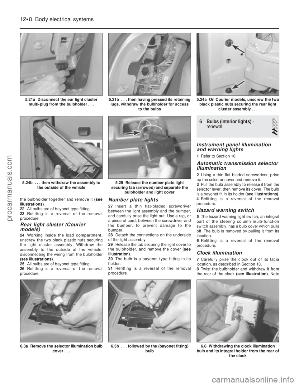
the bulbholder together and remove it (see
illustrations) .
22 All bulbs are of bayonet type fitting.
23 Refitting is a reversal of the removal
procedure.
Rear light cluster (Courier
models)
24 Working inside the load compartment,
unscrew the two black plastic nuts securing
the light cluster assembly. Withdraw the
assembly to the outside of the vehicle,
disconnecting the wiring from the bulbholder
(see illustrations) .
25 All bulbs are of bayonet type fitting.
26 Refitting is a reversal of the removal
procedure.
Number plate lights
27 Insert a thin flat-bladed screwdriver
between the light assembly and the bumper,
and carefully prise the light out. Use a rag, or
a piece of card, between the screwdriver and
the bumper, to prevent damage to the
bumper.
28 Detach the connections on the underside
of the light assembly.
29 Release the tab securing the light cover to
the bulbholder, and remove the cover (see
illustration) .
30 The bulb is a bayonet type fitting in its
holder.
31 Refitting is a reversal of the removal
procedure.
6 Bulbs (interior lights) -
renewal
2
Instrument panel illumination
and warning lights
1 Refer to Section 10.
Automatic transmission selector
illumination
2Using a thin flat-bladed screwdriver, prise
up the selector cover and remove it.
3 Pull the bulb assembly to release it from the
selector lever, then remove its cover. The bulb
is a bayonet fit in its holder (see illustrations).
4 Refitting is a reversal of the removal
procedure.
Hazard warning switch
5 The hazard warning light switch, an integral
part of the steering column multi-function
switch assembly, has a bulb cover which pulls
off. The bulb is removed by pulling it from its
location.
6 Refitting is a reversal of the removal
procedure.
Clock illumination
7 Carefully prise the clock out of its facia
location, as described in Section 13.
8 Twist the bulbholder and withdraw it from
the rear of the clock (see illustration). Note
12•8Body electrical systems
6.8 Withdrawing the clock illumination
bulb and its integral holder from the rear of
the clock6.3b . . . followed by the (bayonet fitting) bulb6.3a Remove the selector illumination bulbcover . . .
5.29 Release the number plate light
securing tab (arrowed) and separate the bulbholder and light cover5.24b . . . then withdraw the assembly to
the outside of the vehicle
5.24a On Courier models, unscrew the twoblack plastic nuts securing the rear light cluster assembly . . .5.21b . . . then having pressed its retaininglugs, withdraw the bulbholder for access to the bulbs5.21a Disconnect the ear light clustermulti-plug from the bulbholder . . .
1595Ford Fiesta Remakeprocarmanuals.com
http://vnx.su
Page 242 of 296
that the bulb and bulbholder cannot be
separated - they are replaced as an assembly.
9Refitting is a reversal of the removal
procedure.
Cigarette lighter illumination
10 Remove the cigarette lighter, as described
in Section 12.
11 Pull the bulbholder from its location in the
illuminated surround, then pull the bulb out of
the bulbholder.
12 Refitting is a reversal of the removal
procedure.
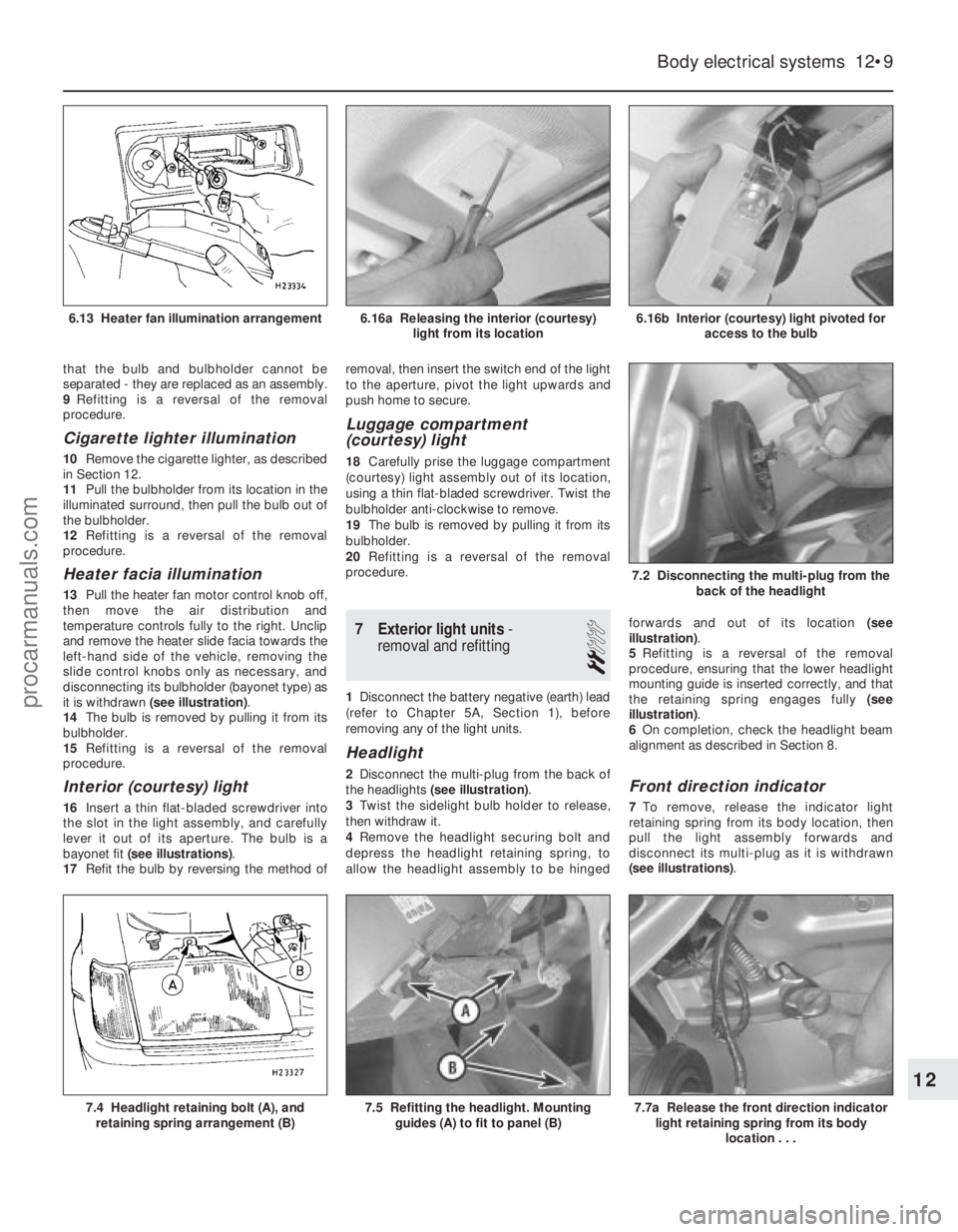
Heater facia illumination
13 Pull the heater fan motor control knob off,
then move the air distribution and
temperature controls fully to the right. Unclip
and remove the heater slide facia towards the
left-hand side of the vehicle, removing the
slide control knobs only as necessary, and
disconnecting its bulbholder (bayonet type) as
it is withdrawn (see illustration) .
14 The bulb is removed by pulling it from its
bulbholder.
15 Refitting is a reversal of the removal
procedure.
Interior (courtesy) light
16 Insert a thin flat-bladed screwdriver into
the slot in the light assembly, and carefully
lever it out of its aperture. The bulb is a
bayonet fit (see illustrations) .
17 Refit the bulb by reversing the method of removal, then insert the switch end of the light
to the aperture, pivot the light upwards and
push home to secure.
Luggage compartment
(courtesy) light
18
Carefully prise the luggage compartment
(courtesy) light assembly out of its location,
using a thin flat-bladed screwdriver. Twist the
bulbholder anti-clockwise to remove.
19 The bulb is removed by pulling it from its
bulbholder.
20 Refitting is a reversal of the removal
procedure.
7 Exterior light units -
removal and refitting
2
1 Disconnect the battery negative (earth) lead
(refer to Chapter 5A, Section 1), before
removing any of the light units.
Headlight
2 Disconnect the multi-plug from the back of
the headlights (see illustration) .
3 Twist the sidelight bulb holder to release,
then withdraw it.
4 Remove the headlight securing bolt and
depress the headlight retaining spring, to
allow the headlight assembly to be hinged forwards and out of its location
(see
illustration) .
5 Refitting is a reversal of the removal
procedure, ensuring that the lower headlight
mounting guide is inserted correctly, and that
the retaining spring engages fully (see
illustration) .
6 On completion, check the headlight beam
alignment as described in Section 8.Front direction indicator
7 To remove, release the indicator light
retaining spring from its body location, then
pull the light assembly forwards and
disconnect its multi-plug as it is withdrawn
(see illustrations) .
Body electrical systems 12•9
6.16b Interior (courtesy) light pivoted for
access to the bulb
7.2 Disconnecting the multi-plug from the
back of the headlight
6.16a Releasing the interior (courtesy)light from its location6.13 Heater fan illumination arrangement
7.7a Release the front direction indicatorlight retaining spring from its body
location . . .7.5 Refitting the headlight. Mountingguides (A) to fit to panel (B)7.4 Headlight retaining bolt (A), andretaining spring arrangement (B)
12
1595Ford Fiesta Remakeprocarmanuals.com
http://vnx.su
Page 249 of 296
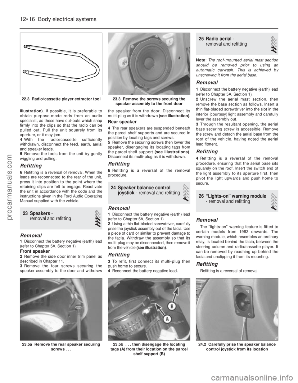
illustration). If possible, it is preferable to
obtain purpose-made rods from an audio
specialist, as these have cut-outs which snap
firmly into the clips so that the radio can be
pulled out. Pull the unit squarely from its
aperture, or it may jam.
4 With the radio/cassette sufficiently
withdrawn, disconnect the feed, earth, aerial
and speaker leads.
5 Remove the tools from the unit by gently
wiggling and pulling.
Refitting
6 Refitting is a reversal of removal. When the
leads are reconnected to the rear of the unit,
press it into position to the point where the
retaining clips are felt to engage. Reactivate
the unit in accordance with the code and the
instructions given in the Ford Audio Operating
Manual supplied with the vehicle.
23 Speakers -
removal and refitting
3
Removal
1 Disconnect the battery negative (earth) lead
(refer to Chapter 5A, Section 1).
Front speaker
2 Remove the side door inner trim panel as
described in Chapter 11.
3 Remove the four screws securing the
speaker assembly to the door and withdraw the speaker from the door. Disconnect its
multi-plug as it is withdrawn
(see illustration).
Rear speaker
4The rear speakers are suspended beneath
the parcel shelf supports and are secured in
position by locating tags and screws.
5 Remove the securing screws then lower the
speaker, disengaging its locating tags from
the parcel shelf support (see illustrations).
Disconnect its multi-plug as it is withdrawn.
Refitting
6 Refitting is a reversal of the removal
procedure.
24 Speaker balance control
joystick - removal and refitting
1
Removal
1Disconnect the battery negative (earth) lead
(refer to Chapter 5A, Section 1).
2 Using a thin flat-bladed screwdriver, carefully
prise the joystick assembly out of the facia. Use
a piece of card or similar to prevent damage to
the facia. Withdraw the assembly so that its
multi-plug may be disconnected, then remove it
from the vehicle (see illustration) .
Refitting
3To refit, first connect its multi-plug then
push home to secure.
4 Reconnect the battery negative lead.
25 Radio aerial -
removal and refitting
2
Note : The roof-mounted aerial mast section
should be removed prior to using an
automatic carwash. This is achieved by
unscrewing it from the aerial base.
Removal
1 Disconnect the battery negative (earth) lead
(refer to Chapter 5A, Section 1).
2 Unscrew the aerial mast section, then
remove the base section as follows. Insert a
thin flat-bladed screwdriver into the slot in the
interior (courtesy) light assembly and carefully
lever the assembly out.
3 Through the resultant opening, the aerial
base securing screw is accessible. Remove
the screw and detach the aerial base from the
roof of the vehicle, having noted the aerial
lead fitment.
Refitting
4 Refitting is a reversal of the removal
procedure, ensuring that the aerial base sits
squarely on the roof. Insert the switch end of
the light assembly to its aperture first, then
pivot the light upwards and push home to
secure.
26 “Lights-on” warning module
- removal and refitting
1
Removal
The “lights-on” warning feature is fitted to
certain models from 1993 onwards. The
warning module, which resembles an ordinary
relay, is located behind the facia, between the
steering column and radio/cassette player. It
can be removed by reaching up behind the
facia and unclipping it from its mounting.
Refitting
Refitting is a reversal of removal.
12•16 Body electrical systems
24.2 Carefully prise the speaker balance control joystick from its location23.5b . . . then disengage the locating
tags (A) from their location on the parcel
shelf support (B)23.5a Remove the rear speaker securing screws . . .
23.3 Remove the screws securing thespeaker assembly to the front door22.3 Radio/cassette player extractor tool
1595Ford Fiesta Remakeprocarmanuals.com
http://vnx.su
Page 261 of 296
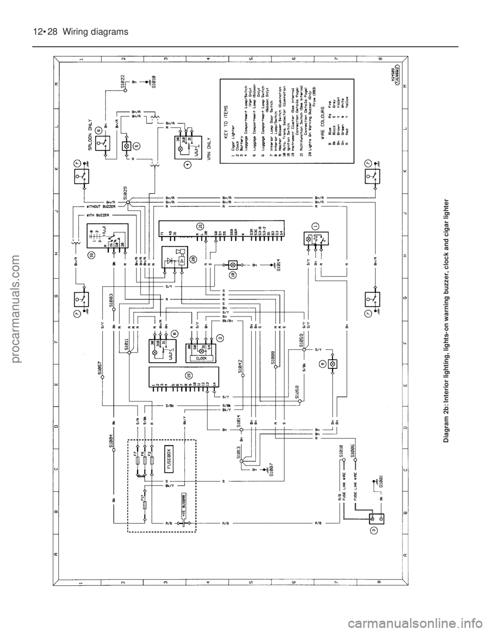
12•28 Wiring diagrams
Diagram 2b: Interior lighting, lights-on warning buzzer, clock and cigar\
lighter
1595Ford Fiesta Remakeprocarmanuals.com
http://vnx.su
Page 294 of 296
Fault finding - clutch - REF•17
Fault finding - cooling system - REF•16
Fault finding - driveshafts - REF•19
Fault finding - electrical system - 5A•2,
12 •3, REF •20
Fault finding - engine - REF•15, REF•16,
REF•18
Fault finding - fuel and exhaust systems -
REF•17
Fault finding - manual transmission - REF•17
Fault finding - suspension and steering
systems - REF•19
Filling - 11•3
Filter, air -1•22, 1•23, 4A•3, 4B•4, 4C•3,
4D•3, 4E•5
Filter, oil -1•9
Filter, fuel -1•25
Fire - 0•5
Float - 4A•7, 4A•9, 4A•16
Fluid seals - 7B•3
Fluids - 0•17
Flywheel - 2A•11, 2B•14, 2C•16
Fuel consumption high - REF•17
Fuel cut-off switch - 4B•5, 4C•5, 4D•4
Fuel filler pipe - 4A•6, 4B•5, 4C•5, 4D•4
Fuel filter - 1•25
Fuel gauge - 4A•6, 4B•4, 4C•5, 4D•4, 12 •12
Fuel gauge fault - REF•20
Fuel hoses - 1•13
Fuel injectors - 4B•5, 4C•5, 4D•5
Fuel lines - 1•17, 4B•3, 4C•3, 4D•2
Fuel pressure check - 4C•4
Fuel pressure regulator - 4B•6, 4C•6, 4D•5
Fuel pump - 4A•5, 4B•4, 4C•4, 4C•5, 4D•4
Fuel rail - 4C•5, 4D•5
Fuel system - carburettor engines -4A•1 et
seq
Fuel system - central fuel injection engines
-4B•1 et seq
Fuel system - electronic fuel injection engines -4C•1 et seq
Fuel system - sequential electronic fuel
injection engines -4D•1 et seq
Fuel and exhaust systems - REF•13
Fuel and exhaust systems fault finding - REF•17
Fuel tank - 4A•5, 4A•6, 4B•4, 4B•5, 4C•5,
4D•4
Fuel trap - 4B•7
Fume or gas intoxication - 0•5
Fuses - 0•16, 12 •4
G
Gaiters - 1•16, 8•3, 8•4, 10 •15
Gashes in bodywork - 11•3
Gaskets - REF •4
Gear lever - 7A•2
Gear selection problems - REF•18
Gear selector - 7B•2
Gearbox oil - 0•17, 1•14
Gearbox - See Manual gearbox
Gearchange linkage - 7A•2
Gearchange selector - 7A•3
Glossary of technical terms - REF•22 et seq
Grab handle - 11•20
H
Handbrake - 1•25, 9•12, 9•13, 12 •6,
REF•10
Handles - 11•11, 11•13, 11 •20
Hazard warning switch - 12•8
HC emissions - REF•13
HCS engine in-car repair procedures -
2A•1 et seq
Headlight - 12•7, 12 •9, 12 •10
Heater - 3•2, 3•8, 12 •6, 12•9
Horn - 12•12
Horn fault - REF•20
HT lead - 1•20
Hub bearings - 10•5, 10•8, REF •12
Hydraulic pipes and hoses - 9•9
Hydraulic tappets - 2C•8
Hydrofluoric acid - 0•5
I
Idle speed -1•14, 1•15, 1•20, 4C•6
Idle speed control valve - 4D•6
Idling fault - REF•15
Ignition amplifier - 5B•5
Ignition switch - 12•5
Ignition system -5B•1 et seq
Ignition fault - REF•20
Ignition timing - 5B•7
Indicators - 12•7, 12•9, 12 •10
Injector ballast resistor - 4B•9
Injectors - 4C•5, 4D•5
Inlet manifold - 4A•18, 4B•9, 4C•8, 4D•7
Instruments - 1•18, 12•8, 12•11
Instrument fault - REF•20
Intercooler - 4C•8
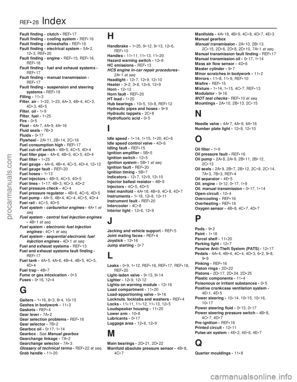
Interior light - 12•6, 12 •9
J
Jacking and vehicle support - REF•5
Joint mating faces - REF•4
Joystick - 12•16
Jump starting - 0•7
L
Leaks -0•9, 1•12, REF •16, REF•17, REF•18,
REF•20
Light-laden valve - 9•13, 9•14
Lighter - 12•9, 12 •12
Lights-on warning module - 12•16
Load compartment - 11•20
Load-apportioning valve - 9•16
Locknuts ,locktabs and washers - REF•4
Locks - 11•11, 11•12, 11•13, 12 •5
Loudspeaker housing - 11•20
Lower arm - 10•8
Lubricants - 0•17
Luggage area - 12•6, 12•9
M
Main bearings - 2D•21, 2D•22
Manifold absolute pressure sensor - 4B•8,
4C•7 Manifolds -
4A•18, 4B•9, 4C•8, 4D•7, 4E•3
Manual gearbox
Manual transmission -2A•10, 2B•13,
2C•15, 2D•6, 2D•8, 2D•10, 7A•1 et seq
Manual transmission fault finding - REF•17
Manual transmission oil - 0•17, 1•14
Mass air flow sensor - 4D•6
Master cylinder - 9•7
Minor scratches in bodywork - 11•2
Mirrors - 11 •8, 11•9, REF •10
Misfire - REF•15
Mixture - 1•14, 1•15, 4C•7, REF•13
Modulator - 9•16
MOT test checks - REF•10et seq
Mountings - 2A•10, 2B•13, 2C•15
N
Needle valve - 4A•7, 4A•9, 4A•16
Number plate light - 12•8, 12 •10
O
Oil filter - 1•9
Oil pressure fault - REF•16
Oil pump - 2A•8, 2A•9, 2B•11, 2B•12,
2C•13
Oil seals - 2A•9, 2B•7, 2B•12, 2C•8, 2C•14,
7A•3, 7B•3, REF •4
Oil separator - 4E•5
Oil, engine - 0•12, 0•17, 1•9
Oil, manual transmission - 0•17, 1•14
Open-circuit - 12•4
Overcooling - REF•16
Overheating - REF•16
Oxygen sensor - 4B•8, 4C•7, 4D•7
P
Pads -9•2
Paint - 1•18
Parcel shelf - 11•20
Parking light - 12•7
Passive Anti-Theft System (PATS) - 12•17
Pedals - 4A•4, 4B•4, 4C•4, 4D•3, 6•2, 9•8,
9•9
Pinking - REF•16
Piston rings - 2D•22
Pistons - 2D•17, 2D•24, 2D•25
Plastic components - 11•4
Poisonous or irritant substances - 0•5
Positive crankcase ventilation system - 4E•1, 4E•5
Power steering - 10•14, 10•15, 10•16,
10 •17
Power steering fluid - 0•13, 0•17
Power steering pressure switch - 4B•8,
4C•7, 4D•7
Pre-ignition - REF•16
Printed circuit - 12•11
Pulse-air system - 4E•2, 4E•6, 4E•7
Q
Quarter mouldings - 11•8
REF•28Index
1595 Ford Fiesta Remakeprocarmanuals.com
http://vnx.su