horn FORD FIESTA 1989 Service Repair Manual
[x] Cancel search | Manufacturer: FORD, Model Year: 1989, Model line: FIESTA, Model: FORD FIESTA 1989Pages: 296, PDF Size: 10.65 MB
Page 8 of 296
Maintenance – component location1•7
1
1595Ford Fiesta Remake
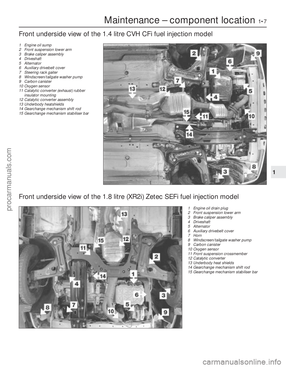
Front underside view of the 1.4 litre CVH CFi fuel injection model
1 Engine oil sump
2 Front suspension lower arm
3 Brake caliper assembly
4 Driveshaft
5 Alternator
6 Auxiliary drivebelt cover
7 Steering rack gaiter
8 Windscreen/tailgate washer pump
9 Carbon canister
10 Oxygen sensor
11 Catalytic converter (exhaust) rubber
insulator mounting
12 Catalytic converter assembly
13 Underbody heatshields
14 Gearchange mechanism shift rod
15 Gearchange mechanism stabiliser bar
Front underside view of the 1.8 litre (XR2i) Zetec SEFi fuel injection model
1 Engine oil drain plug
2 Front suspension lower arm
3 Brake caliper assembly
4 Driveshaft
5 Alternator
6 Auxiliary drivebelt cover
7 Horn
8 Windscreen/tailgate washer pump
9 Carbon canister
10 Oxygen sensor
11 Front suspension crossmember
12 Catalytic converter
13 Underbody heat shields
14 Gearchange mechanism shift rod
15 Gearchange mechanism stabiliser bar
procarmanuals.com
http://vnx.su
Page 142 of 296
and flexible hose connecting the turbocharger
to the intercooler (see illustration 4.12) . Use
adhesive tape to seal the turbocharger ports
against the entry of dirt.
3 Unbolt the horn nearest the intercooler.
4 Unbolt the radiator/intercooler assembly
from the bonnet closure panel and the body
crossmember.
5 Move the assembly as far as possible
towards the engine, and unbolt the intercooler
from the radiator; withdraw the intercooler.
Refitting
6 Refitting is the reverse of the removal
procedure, tightening all nuts and bolts to the
specified torque settings, and not forgetting
to unseal the turbocharger openings before
reconnecting the intercooler pipe and hose.
18 Turbocharger boost control valve - removal and refitting
2
Removal
1Disconnect the battery negative (earth) lead
(refer to Chapter 5A, Section 1).
2 Disconnect the control valve wiring at its
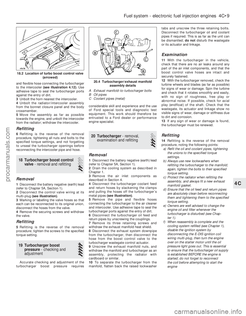
multi-plug (see illustration) .
3 Marking or labelling the valve hoses so that
each can be reconnected to its original union,
disconnect the hoses from the valve.
4 Remove the securing screws and withdraw
the valve.
Refitting
5 Refitting is the reverse of the removal
procedure; tighten the screws to the specified
torque setting.
19 Turbocharger boost pressure - checking and
adjustment
5
Accurate checking and adjustment of the
turbocharger boost pressure requires considerable skill and experience and the use
of Ford special tools and diagnostic test
equipment. This work should therefore be
entrusted to a Ford dealer or performance
engine specialist.
20 Turbocharger
- removal,
examination and refitting
3
Removal
1 Disconnect the battery negative (earth) lead
(refer to Chapter 5A, Section 1).
2 Drain the cooling system as described in
Chapter 1.
3 Remove the air inlet components as
described in Section 4.
4 Disconnect the turbocharger coolant feed
and return hoses by slackening the clamps
and pulling the hoses off the turbocharger’s
metal pipes (see illustration) .
5 Remove the pipe and flexible hoses
connecting the turbocharger to the air cleaner
and intercooler. Use adhesive tape to seal the
turbocharger ports against the entry of dirt.
6 Disconnect the turbocharger oil feed and
return pipes by unscrewing the couplings.
7 Remove its three retaining screws and
withdraw the exhaust manifold heat shield.
8 Disconnect the exhaust system downpipe
from the turbocharger, then disconnect the
hose from the boost control valve to the
turbocharger wastegate control actuator.
9 Unscrew the exhaust manifold nuts, and
withdraw the manifold and turbocharger as an
assembly, protecting the radiator with
cardboard or similar.
10 To separate the turbocharger from the
manifold, flatten back the raised lockwasher tabs and unscrew the three retaining bolts.
Disconnect the turbocharger oil and coolant
pipes if required. This is as far as the unit can
be dismantled;
do notdisturb the wastegate
or its actuator and linkage.
Examination
11 With the turbocharger in the vehicle,
check that there are no air leaks around any
part of the air inlet components, and that the
boost control valve hoses are intact and
securely fastened.
12 With the turbocharger removed, check the
turbine wheels and blades (as far as possible)
for signs of wear or damage. Spin the turbine
and check that it rotates smoothly and easily,
with no sign of roughness, free play or
abnormal noise. If possible, check for axial
play (endfloat) of the shaft. Check that the
wastegate, its actuator and linkage show no
visible signs of wear, damage or stiffness due
to dirt and corrosion.
13 If any sign of wear or damage is found,
the turbocharger must be renewed.
Refitting
14 Refitting is the reverse of the removal
procedure, noting the following points: a) Refit the oil and coolant pipes, tightening
the unions to the specified torque
settings.
b) Always use new lockwashers when
refitting the turbocharger to the manifold;
again, tighten the bolts to their specified
torque setting.
c) Protect the radiator when refitting the
assembly, and always fit a new exhaust
manifold gasket.
d) Ensure that the oil feed and return pipes
are absolutely clean before reconnecting
them and tightening them to the specified
torque setting.
e) Owners are well advised to change the engine oil and filter whenever the
turbocharger is disturbed (see Chap-
ter 1).
f) When reassembly is complete and the
cooling system refilled (see Chapter 1),
disable the ignition system by
disconnecting the E-DIS ignition coil
wiring multi-plug, then turn the engine
over on the starter motor until the oil
pressure light goes out. This is essential
to ensure that the turbocharger oil supply
is established BEFORE the engine is
started; do not forget to reconnect
the coil before attempting to start the
engine
Fuel system - electronic fuel injection engines 4C•9
20.4 Turbocharger/exhaust manifold assembly details
A Exhaust manifold-to-turbocharger bolts
B Oil pipes
C Coolant pipes (metal)
4C
1595Ford Fiesta Remake
18.2 Location of turbo boost control valve (arrowed)
procarmanuals.com
http://vnx.su
Page 234 of 296
 Circuit(s) protected
1 3 . . . . . . . . . . . . . . . . . . . . . . . . . . . . . . . . . . . .\
. . . . . . . .")
12
1595Ford Fiesta Remake
Fuses - pre-1992 models
Main fuse board:
No Rating (amps) Circuit(s) protected
1 3 . . . . . . . . . . . . . . . . . . . . . . . . . . . . . . . . . . . .\
. . . . . . . . . . . . . Electronic engine control system
2 15 . . . . . . . . . . . . . . . . . . . . . . . . . . . . . . . . . . . .\
. . . . . . . . . . . . Interior light, cigarette lighter, clock and radio memory
3 20 . . . . . . . . . . . . . . . . . . . . . . . . . . . . . . . . . . . .\
. . . . . . . . . . . . Central locking system
4 30 . . . . . . . . . . . . . . . . . . . . . . . . . . . . . . . . . . . .\
. . . . . . . . . . . . Heated rear window element
5 10 . . . . . . . . . . . . . . . . . . . . . . . . . . . . . . . . . . . .\
. . . . . . . . . . . . Dim-dip lighting
6 10 . . . . . . . . . . . . . . . . . . . . . . . . . . . . . . . . . . . .\
. . . . . . . . . . . . Left-hand side lights and rear fog light
7 10 . . . . . . . . . . . . . . . . . . . . . . . . . . . . . . . . . . . .\
. . . . . . . . . . . . Right-hand side lights
8 10 . . . . . . . . . . . . . . . . . . . . . . . . . . . . . . . . . . . .\
. . . . . . . . . . . . Left-hand dipped beam
9 10 . . . . . . . . . . . . . . . . . . . . . . . . . . . . . . . . . . . .\
. . . . . . . . . . . . Right-hand dipped beam
10 15 . . . . . . . . . . . . . . . . . . . . . . . . . . . . . . . . . . . .\
. . . . . . . . . . . . Left-hand main beam and right-hand auxiliary driving light
11 15 . . . . . . . . . . . . . . . . . . . . . . . . . . . . . . . . . . . .\
. . . . . . . . . . . . Right-hand main beam and left-hand auxiliary driving light
12 20 . . . . . . . . . . . . . . . . . . . . . . . . . . . . . . . . . . . .\
. . . . . . . . . . . . Heater fan motor and reversing light
13 30 . . . . . . . . . . . . . . . . . . . . . . . . . . . . . . . . . . . .\
. . . . . . . . . . . . Radiator cooling fan motor
14 15 . . . . . . . . . . . . . . . . . . . . . . . . . . . . . . . . . . . .\
. . . . . . . . . . . . Front foglights (XR2i only)
15 15 . . . . . . . . . . . . . . . . . . . . . . . . . . . . . . . . . . . .\
. . . . . . . . . . . . Horn
16 20 . . . . . . . . . . . . . . . . . . . . . . . . . . . . . . . . . . . .\
. . . . . . . . . . . . Wiper motor and windscreen/tailgate washer pump
17 10 . . . . . . . . . . . . . . . . . . . . . . . . . . . . . . . . . . . .\
. . . . . . . . . . . . Brake stop lights, instrument illumination and instrument warning
18 30 . . . . . . . . . . . . . . . . . . . . . . . . . . . . . . . . . . . .\
. . . . . . . . . . . . Electrically operated windows
19 20 . . . . . . . . . . . . . . . . . . . . . . . . . . . . . . . . . . . .\
. . . . . . . . . . . . Electric fuel pump
20 10 . . . . . . . . . . . . . . . . . . . . . . . . . . . . . . . . . . . .\
. . . . . . . . . . . . Oxygen sensor (vehicles with catalytic converter)
21 10 . . . . . . . . . . . . . . . . . . . . . . . . . . . . . . . . . . . .\
. . . . . . . . . . . . Left-hand direction indicators
22 10 . . . . . . . . . . . . . . . . . . . . . . . . . . . . . . . . . . . .\
. . . . . . . . . . . . Right-hand direction indicators
Chapter 12
Body electrical systems
Air bag (driver’s side) - removal and refitting . . . . . . . . . . . . . . . . . . 28
Air bag (passenger’s side) - removal and refitting . . . . . . . . \
. . . . . . . 29
Air bag clock spring - removal and refitting . . . . . . . . . . . . . . . . . . . 31
Air bag control module - removal and refitting . . . . . . . . . . . . . . . . . 30
Anti-theft systems - general information . . . . . . . . . . . . . . . . . . . . . . 27
Battery, bulbs and fuses . . . . . . . . . . . . . . . . . . . .See
“Weekly checks”
Bulbs (exterior lights) - renewal . . . . . . . . . . . . . . . . . . . . . . . . . . . . . 5
Bulbs (interior lights) - renewal . . . . . . . . . . . . . . . . . . . . . . . . . . . . . 6
Cigarette lighter - removal and refitting . . . . . . . . . . . . . . . . . . . . . . 12
Clock - removal and refitting . . . . . . . . . . . . . . . . . . . . . . . . . . . . . . . 13
Electric window regulator motor - removal and refitting . . . . . . . . . . 20
Electrical fault-finding - general information . . . . . . . . . . . . . . . . . . . 2
Exterior light units - removal and refitting . . . . . . . . . . . . . . . . . . . . . 7
Fuses and relays - general information . . . . . . . . . . . . . . . . . . . . . . . 3
General information and precautions . . . . . . . . . . . . . . . . . . . . . . . . 1
Headlight and auxiliary light beam alignment - checking and
adjustment . . . . . . . . . . . . . . . . . . . . . . . . . . . . . . . . . . . .\
. . . . . . . 8
Horn - removal and refitting . . . . . . . . . . . . . . . . . . . . . . . . . . . . . . . 14 Instrument panel - removal and refitting . . . . . . . . . . . . . . . . . . . . . . 9
Instrument panel components - removal and refitting . . . . . . . . . . . 10
“Lights-on” warning module - removal and refitting . . . . . . . . . . . . . 26
Radio aerial - removal and refitting . . . . . . . . . . . . . . . . . . . . . . . . . . 25
Radio/cassette player - removal and refitting . . . . . . . . . . . . . . . . . . 22
Screen washer fluid level check . . . . . . . . . . . . . .See
“Weekly checks”
Speaker balance control joystick - removal and refitting . . . . . . . . . 24
Speakers - removal and refitting . . . . . . . . . . . . . . . . . . . . . . . . . . . . 23
Speedometer cable - removal and refitting . . . . . . . . . . . . . . . . . . . . 11
Switches - removal and refitting . . . . . . . . . . . . . . . . . . . . . . . . . . . . 4
Tailgate remote release motor - removal and refitting . . . . . . . . . . . 21
Tailgate wiper motor assembly - removal and refitting . . . . . . . . . . . 18
Windscreen wiper motor and linkage - removal and refitting . . . . . . 16
Windscreen wiper pivot shaft - removal and refitting . . . . . . . . . . . . 17
Windscreen/tailgate washer system components - removal and refitting . . . . . . . . . . . . . . . . . . . . . . . . . . . . . . . . . . . .\
. . . . . . . . . . 19
Wiper arms - removal and refitting . . . . . . . . . . . . . . . . . . . . . . . . . . 15
Wiper blade check . . . . . . . . . . . . . . . . . . . . . . . .See “Weekly checks”
12•1
Specifications Contents
Easy,suitable for
novice with little
experience Fairly easy,
suitable
for beginner with
some experience Fairly difficult,
suitable for competent
DIY mechanic
Difficult,
suitable for
experienced DIY
mechanic Very difficult,
suitable for expert DIY
or professional
Degrees of difficulty
54321
procarmanuals.com
http://vnx.su
Page 235 of 296
 Circuit(s) protected
23 - . . . . . . . . . . . . . . . . . . . . . . . . . . . . . . . . . . . .\
. . . . . . . . . . . . . Unused
24/25 10")
Additional fuses behind main fuse board:
NoRating (amps) Circuit(s) protected
23 - . . . . . . . . . . . . . . . . . . . . . . . . . . . . . . . . . . . .\
. . . . . . . . . . . . . Unused
24/25 10 . . . . . . . . . . . . . . . . . . . . . . . . . . . . . . . . . . . .\
. . . . . . . . . . . . Rear fog lights
26 15 . . . . . . . . . . . . . . . . . . . . . . . . . . . . . . . . . . . .\
. . . . . . . . . . . . Tailgate remote release
27/28 30 . . . . . . . . . . . . . . . . . . . . . . . . . . . . . . . . . . . .\
. . . . . . . . . . . . Heated windscreen
Fuses - 1992 models onward
Main fuse board:
Fuses 1 to 22 . . . . . . . . . . . . . . . . . . . . . . . . . . . . . . . . . . . .\
. . . . . . . . . Unchanged from pre-1992 models
Additional fuses behind main fuse board:
No Rating (amps) Circuit(s) protected
23* - . . . . . . . . . . . . . . . . . . . . . . . . . . . . . . . . . . . .\
. . . . . . . . . . . . . . Unused
23** 10 . . . . . . . . . . . . . . . . . . . . . . . . . . . . . . . . . . . .\
. . . . . . . . . . . . Rear fog lights
24* - . . . . . . . . . . . . . . . . . . . . . . . . . . . . . . . . . . . .\
. . . . . . . . . . . . . . Unused 24** 10 . . . . . . . . . . . . . . . . . . . . . . . . . . . . . . . . . . . .\
. . . . . . . . . . . . Rear fog lights
25 15 . . . . . . . . . . . . . . . . . . . . . . . . . . . . . . . . . . . .\
. . . . . . . . . . . . Tailgate remote release, anti-theft warning system
26 30 . . . . . . . . . . . . . . . . . . . . . . . . . . . . . . . . . . . .\
. . . . . . . . . . . . Heated windscreen
27 30 . . . . . . . . . . . . . . . . . . . . . . . . . . . . . . . . . . . .\
. . . . . . . . . . . . Heated windscreen
28* 20 . . . . . . . . . . . . . . . . . . . . . . . . . . . . . . . . . . . .\
. . . . . . . . . . . . Full-length sunroof
28** 30 . . . . . . . . . . . . . . . . . . . . . . . . . . . . . . . . . . . .\
. . . . . . . . . . . . Automatic transmission starter inhibitor
29 10 . . . . . . . . . . . . . . . . . . . . . . . . . . . . . . . . . . . .\
. . . . . . . . . . . . Air bag
* Pre-1994 models
** 1994 models onward
Relays (pre-1992 models)
Note: Relay locations and circuits controlled are liable to change from year t\
o year. Consult a Ford dealer, for specific information.
No Circuit(s) controlled
I . . . . . . . . . . . . . . . . . . . . . . . . . . . . . . . . . . . .\
. . . . . . . . . . . . . . Heated rear window
II . . . . . . . . . . . . . . . . . . . . . . . . . . . . . . . . . . . .\
. . . . . . . . . . . . . . Windscreen wiper delay
III . . . . . . . . . . . . . . . . . . . . . . . . . . . . . . . . . . . .\
. . . . . . . . . . . . . . CFi (fuel injection) delay relay
IV . . . . . . . . . . . . . . . . . . . . . . . . . . . . . . . . . . . .\
. . . . . . . . . . . . . . Not used on UK models
V . . . . . . . . . . . . . . . . . . . . . . . . . . . . . . . . . . . .\
. . . . . . . . . . . . . . Ignition switch
VI . . . . . . . . . . . . . . . . . . . . . . . . . . . . . . . . . . . .\
. . . . . . . . . . . . . . Automatic transmission starter inhibitor/electric fuel pump (bridge fitted to carburettor engines without automatic transmission)
VII . . . . . . . . . . . . . . . . . . . . . . . . . . . . . . . . . . . .\
. . . . . . . . . . . . . . Headlight main beam
VIII . . . . . . . . . . . . . . . . . . . . . . . . . . . . . . . . . . . .\
. . . . . . . . . . . . . . Dim-dip lighting
IX . . . . . . . . . . . . . . . . . . . . . . . . . . . . . . . . . . . .\
. . . . . . . . . . . . . . Not used on UK models
X . . . . . . . . . . . . . . . . . . . . . . . . . . . . . . . . . . . .\
. . . . . . . . . . . . . . Not used on UK models
XI . . . . . . . . . . . . . . . . . . . . . . . . . . . . . . . . . . . .\
. . . . . . . . . . . . . . Heated windscreen
XII . . . . . . . . . . . . . . . . . . . . . . . . . . . . . . . . . . . .\
. . . . . . . . . . . . . . Anti-lock braking system
A . . . . . . . . . . . . . . . . . . . . . . . . . . . . . . . . . . . .\
. . . . . . . . . . . . . . Idle speed control (automatic transmission) two-tone horn (where fitt\
ed)
B . . . . . . . . . . . . . . . . . . . . . . . . . . . . . . . . . . . .\
. . . . . . . . . . . . . . Not used on UK models
C . . . . . . . . . . . . . . . . . . . . . . . . . . . . . . . . . . . .\
. . . . . . . . . . . . . . Front foglights (XR2i)
D . . . . . . . . . . . . . . . . . . . . . . . . . . . . . . . . . . . .\
. . . . . . . . . . . . . . Headlight dipped beam
E . . . . . . . . . . . . . . . . . . . . . . . . . . . . . . . . . . . .\
. . . . . . . . . . . . . . Dim-dip lighting
Relays (1992 models onward)
Note: Relay locations and circuits controlled are liable to change from year t\
o year. Consult a Ford dealer, for specific information.
No Circuit(s) controlled
I . . . . . . . . . . . . . . . . . . . . . . . . . . . . . . . . . . . .\
. . . . . . . . . . . . . . Heated rear window
II . . . . . . . . . . . . . . . . . . . . . . . . . . . . . . . . . . . .\
. . . . . . . . . . . . . . Windscreen wiper delay
III . . . . . . . . . . . . . . . . . . . . . . . . . . . . . . . . . . . .\
. . . . . . . . . . . . . . CFi delay relay or EFi supply relay (fuel injection)
IV . . . . . . . . . . . . . . . . . . . . . . . . . . . . . . . . . . . .\
. . . . . . . . . . . . . . Not used on UK models
V . . . . . . . . . . . . . . . . . . . . . . . . . . . . . . . . . . . .\
. . . . . . . . . . . . . . Ignition switch
VI . . . . . . . . . . . . . . . . . . . . . . . . . . . . . . . . . . . .\
. . . . . . . . . . . . . . Automatic transmission starter inhibitor, anti-theft warning system
VII . . . . . . . . . . . . . . . . . . . . . . . . . . . . . . . . . . . .\
. . . . . . . . . . . . . . Headlight main beam
VIII . . . . . . . . . . . . . . . . . . . . . . . . . . . . . . . . . . . .\
. . . . . . . . . . . . . . Anti-lock braking system and/or dim-dip lighting
IX . . . . . . . . . . . . . . . . . . . . . . . . . . . . . . . . . . . .\
. . . . . . . . . . . . . . Not used on UK models
X . . . . . . . . . . . . . . . . . . . . . . . . . . . . . . . . . . . .\
. . . . . . . . . . . . . . Not used on UK models
XI . . . . . . . . . . . . . . . . . . . . . . . . . . . . . . . . . . . .\
. . . . . . . . . . . . . . Heated windscreen
XII . . . . . . . . . . . . . . . . . . . . . . . . . . . . . . . . . . . .\
. . . . . . . . . . . . . . Anti-lock braking system
A . . . . . . . . . . . . . . . . . . . . . . . . . . . . . . . . . . . .\
. . . . . . . . . . . . . . Idle speed control (automatic transmission) or two-tone horn (where f\
itted)
B . . . . . . . . . . . . . . . . . . . . . . . . . . . . . . . . . . . .\
. . . . . . . . . . . . . . Fuel pump
C . . . . . . . . . . . . . . . . . . . . . . . . . . . . . . . . . . . .\
. . . . . . . . . . . . . . Front foglights (XR2i, RS Turbo and RS 1800)
D . . . . . . . . . . . . . . . . . . . . . . . . . . . . . . . . . . . .\
. . . . . . . . . . . . . . Headlight dipped beam
E . . . . . . . . . . . . . . . . . . . . . . . . . . . . . . . . . . . .\
. . . . . . . . . . . . . . Dim-dip lighting
F . . . . . . . . . . . . . . . . . . . . . . . . . . . . . . . . . . . .\
. . . . . . . . . . . . . . Not used on UK models
12•2 Body electrical systems
1595Ford Fiesta Remakeprocarmanuals.com
http://vnx.su
Page 236 of 296
 . . . . . . . . . . . . . . . . . . . . . . . . . . . . . . . . . . . .\
. . . . . H4, 60/55
Sidelight (front) . . . . . . . . . . . . . . . . . . . . . . . . . . .")
BulbsWattage
Headlight (halogen) . . . . . . . . . . . . . . . . . . . . . . . . . . . . . . . . . . . .\
. . . . . H4, 60/55
Sidelight (front) . . . . . . . . . . . . . . . . . . . . . . . . . . . . . . . . . . . .\
. . . . . . . . 5
Direction indicators (main) . . . . . . . . . . . . . . . . . . . . . . . . . . . . . . . . . . . 21
Side direction indicator repeaters . . . . . . . . . . . . . . . . . . . . . . . . . . . . . . 5
Auxiliary driving and foglights (S and XR2i) . . . . . . . . . . . . . . . . . . . . . . H3, 55
Stop/tail light . . . . . . . . . . . . . . . . . . . . . . . . . . . . . . . . . . . .\
. . . . . . . . . . 21/5
Rear foglight . . . . . . . . . . . . . . . . . . . . . . . . . . . . . . . . . . . .\
. . . . . . . . . . 21
Reversing light . . . . . . . . . . . . . . . . . . . . . . . . . . . . . . . . . . . .\
. . . . . . . . 21
Number plate light . . . . . . . . . . . . . . . . . . . . . . . . . . . . . . . . . . . .\
. . . . . 10
Interior light . . . . . . . . . . . . . . . . . . . . . . . . . . . . . . . . . . . .\
. . . . . . . . . . . 10
Luggage compartment light . . . . . . . . . . . . . . . . . . . . . . . . . . . . . . . . . . 5
Instrument warning lights . . . . . . . . . . . . . . . . . . . . . . . . . . . . . . . . . . . .\
1.3 or 2.6
Panel illumination . . . . . . . . . . . . . . . . . . . . . . . . . . . . . . . . . . . .\
. . . . . . 1.3 or 2.6
Cigarette lighter illumination . . . . . . . . . . . . . . . . . . . . . . . . . . . . . . . . . . 1.4
Automatic transmission selector illumination . . . . . . . . . . . . . . . . . . . . . 2
Lubricants
Grease for windscreen wiper linkage and pivots . . . . . . . . . . . . . . . . . . To Ford specification SAM-1C-911-A
Torque wrench settingsNm lbf ft
Wiper motor to bracket . . . . . . . . . . . . . . . . . . . . . . . . . . . . . . . . . . . .\
. . 8 to 9 6 to 7
Wiper motor bracket to bulkhead/tailgate . . . . . . . . . . . . . . . . . . . . . . . 6 to 8 4 to 6
Windscreen wiper crank to driving shaft nut . . . . . . . . . . . . . . . . . . . . . 22 to 24 16 to 18
Windscreen/tailgate wiper arm retaining nut . . . . . . . . . . . . . . . . . . . . . 17 to 18 12 to 13
Windscreen wiper pivot shaft nut . . . . . . . . . . . . . . . . . . . . . . . . . . . . . . 9 to 12 7 to 9
Windscreen/tailgate washer reservoir securing bolts . . . . . . . . . . . . . . . 2.5 to 3.5 2 to 3
Headlight retaining bolt . . . . . . . . . . . . . . . . . . . . . . . . . . . . . . . . . . . .\
. 5.4 to 7.0 4 to 5
Tail light securing nuts . . . . . . . . . . . . . . . . . . . . . . . . . . . . . . . . . . . .\
. . 1.5 to 2.5 1 to 2
Auxiliary light retaining nut (S models) . . . . . . . . . . . . . . . . . . . . . . . . . . 6.8 to 9.2 5 to 7
Horn bracket retaining bolt . . . . . . . . . . . . . . . . . . . . . . . . . . . . . . . . . . . 24 to 33 18 to 24
Starter inhibitor switch . . . . . . . . . . . . . . . . . . . . . . . . . . . . . . . . . . . .\
. . 9 to 14 7 to 10
Body electrical systems 12•3
12
1595Ford Fiesta Remake
1 General information and
precautions
General information
The electrical system is of 12-volt negative
earth type. Power for the lights and all
electrical accessories is supplied by a
lead/acid battery, which is charged by the
engine-driven alternator.
This Chapter covers repair and service
procedures for the various electrical
components not associated with the engine.
Information on the battery, ignition system,
alternator, and starter motor can be found in
Chapter 5A and B.
All models from 1994 onwards are fitted
with a driver’s air bag, which is designed to
prevent serious chest and head injuries to the
driver during an accident. A similar bag for the
front seat passenger is also available. The
combined sensor and electronics for the air
bag is located next to the steering column
inside the vehicle, and contains a back-up
capacitor, crash sensor, decelerometer,
safety sensor, integrated circuit and
microprocessor. The air bag is inflated by a
gas generator, which forces the bag out of the module cover in the centre of the steering
wheel. A “clock spring” ensures that a good
electrical connection is maintained with the air
bag at all times - as the steering wheel is
turned in each direction, the spring winds and
unwinds.
An anti-theft alarm system is available on
later models, and is triggered if the vehicle is
broken into through the doors, bonnet, or
tailgate. The alarm will also be triggered if the
ignition or audio equipment is tampered with.
Additionally, from the 1994 model year
onwards, a Passive Anti-Theft System (PATS)
is fitted. This system, (which works
independently of the standard alarm) prevents
the engine from being started unless a
specific code, programmed into the ignition
key, is recognised by the PATS transceiver.
Precautions
Warning: Before carrying out
any work on the electrical
system, read through the
precautions given in “Safety
first!” at the beginning of this manual and
in Chapter 5A, Section 1.
Caution: Prior to working on any
component in the electrical system, the
battery negative lead should first be
disconnected, to prevent the possibility of electrical short-circuits and/or fires. If a
radio/cassette player with anti-theft
security code is fitted, refer to the
information given in the reference sections
of this manual before disconnecting the
battery.
2 Electrical fault-finding
-
general information
2
Note: Refer to the precautions given in
“Safety first!” and in Section 1 of this Chapter
before starting work. The following tests relate
to testing of the main electrical circuits, and
should not be used to test delicate electronic
circuits (such as engine management
systems), particularly where an electronic
control unit is used. Also refer to the
precautions given in Chapter 5A, Section 1.
General
1 A typical electrical circuit consists of an
electrical component, any switches, relays,
motors, fuses, fusible links or circuit breakers
related to that component, and the wiring and
connectors which link the component to both
the battery and the chassis. To help to
pinpoint a problem in an electrical circuit,
procarmanuals.com
http://vnx.su
Page 245 of 296
retaining tags, taking care to avoid damaging
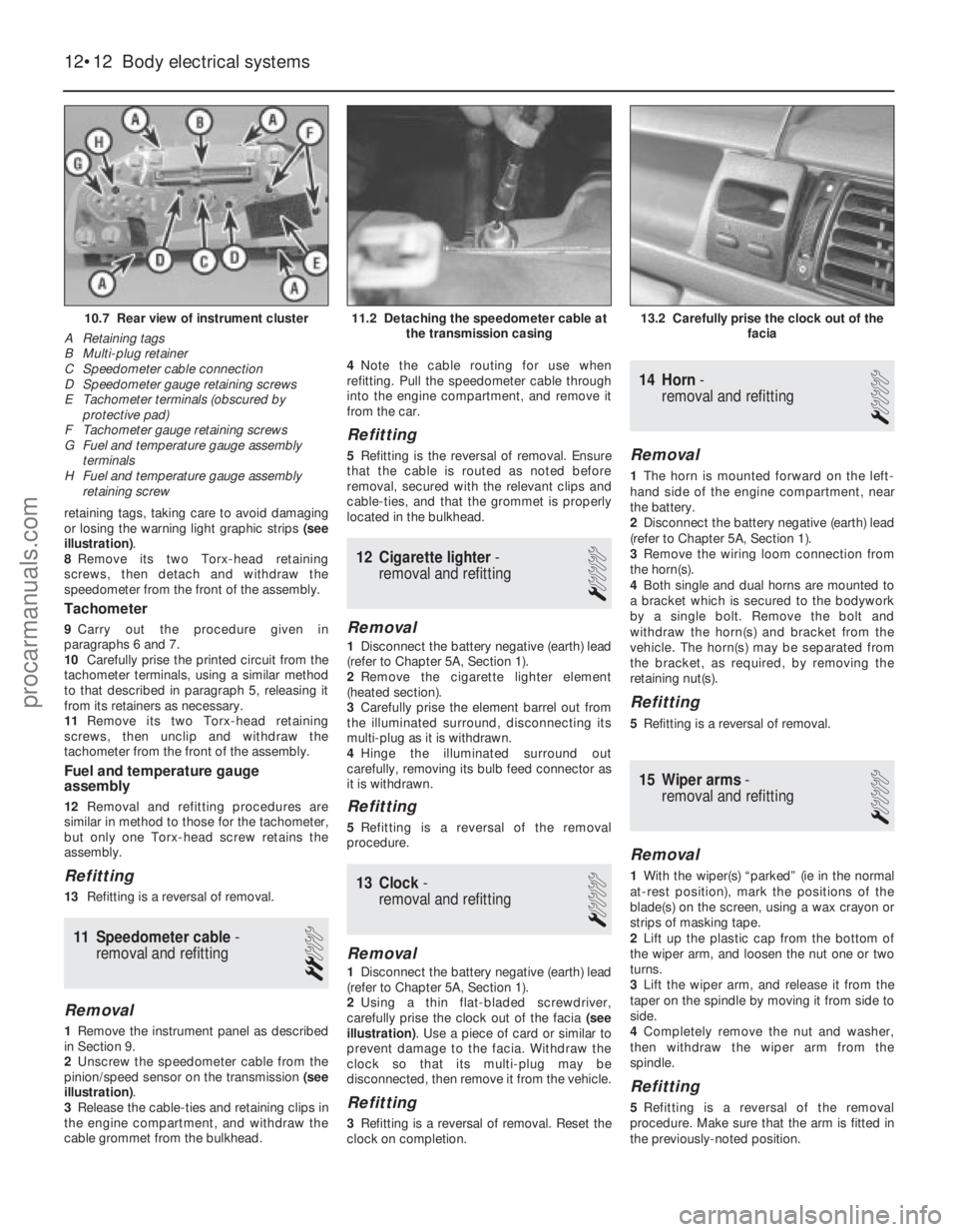
or losing the warning light graphic strips (see
illustration) .
8 Remove its two Torx-head retaining
screws, then detach and withdraw the
speedometer from the front of the assembly.
Tachometer
9 Carry out the procedure given in
paragraphs 6 and 7.
10 Carefully prise the printed circuit from the
tachometer terminals, using a similar method
to that described in paragraph 5, releasing it
from its retainers as necessary.
11 Remove its two Torx-head retaining
screws, then unclip and withdraw the
tachometer from the front of the assembly.
Fuel and temperature gauge
assembly
12 Removal and refitting procedures are
similar in method to those for the tachometer,
but only one Torx-head screw retains the
assembly.
Refitting
13 Refitting is a reversal of removal.
11 Speedometer cable -
removal and refitting
2
Removal
1 Remove the instrument panel as described
in Section 9.
2 Unscrew the speedometer cable from the
pinion/speed sensor on the transmission (see
illustration) .
3 Release the cable-ties and retaining clips in
the engine compartment, and withdraw the
cable grommet from the bulkhead. 4
Note the cable routing for use when
refitting. Pull the speedometer cable through
into the engine compartment, and remove it
from the car.
Refitting
5 Refitting is the reversal of removal. Ensure
that the cable is routed as noted before
removal, secured with the relevant clips and
cable-ties, and that the grommet is properly
located in the bulkhead.
12 Cigarette lighter -
removal and refitting
1
Removal
1 Disconnect the battery negative (earth) lead
(refer to Chapter 5A, Section 1).
2 Remove the cigarette lighter element
(heated section).
3 Carefully prise the element barrel out from
the illuminated surround, disconnecting its
multi-plug as it is withdrawn.
4 Hinge the illuminated surround out
carefully, removing its bulb feed connector as
it is withdrawn.
Refitting
5 Refitting is a reversal of the removal
procedure.
13 Clock -
removal and refitting
1
Removal
1 Disconnect the battery negative (earth) lead
(refer to Chapter 5A, Section 1).
2 Using a thin flat-bladed screwdriver,
carefully prise the clock out of the facia (see
illustration) . Use a piece of card or similar to
prevent damage to the facia. Withdraw the
clock so that its multi-plug may be
disconnected, then remove it from the vehicle.
Refitting
3 Refitting is a reversal of removal. Reset the
clock on completion.
14 Horn -
removal and refitting
1
Removal
1 The horn is mounted forward on the left-
hand side of the engine compartment, near
the battery.
2 Disconnect the battery negative (earth) lead
(refer to Chapter 5A, Section 1).
3 Remove the wiring loom connection from
the horn(s).
4 Both single and dual horns are mounted to
a bracket which is secured to the bodywork
by a single bolt. Remove the bolt and
withdraw the horn(s) and bracket from the
vehicle. The horn(s) may be separated from
the bracket, as required, by removing the
retaining nut(s).
Refitting
5 Refitting is a reversal of removal.
15 Wiper arms -
removal and refitting
1
Removal
1 With the wiper(s) “parked” (ie in the normal
at-rest position), mark the positions of the
blade(s) on the screen, using a wax crayon or
strips of masking tape.
2 Lift up the plastic cap from the bottom of
the wiper arm, and loosen the nut one or two
turns.
3 Lift the wiper arm, and release it from the
taper on the spindle by moving it from side to
side.
4 Completely remove the nut and washer,
then withdraw the wiper arm from the
spindle.
Refitting
5 Refitting is a reversal of the removal
procedure. Make sure that the arm is fitted in
the previously-noted position.
12•12 Body electrical systems
13.2 Carefully prise the clock out of the facia11.2 Detaching the speedometer cable atthe transmission casing10.7 Rear view of instrument cluster
A Retaining tags
B Multi-plug retainer
C Speedometer cable connection
D Speedometer gauge retaining screws
E Tachometer terminals (obscured by protective pad)
F Tachometer gauge retaining screws
G Fuel and temperature gauge assembly
terminals
H Fuel and temperature gauge assembly retaining screw
1595Ford Fiesta Remakeprocarmanuals.com
http://vnx.su
Page 262 of 296
, heate\
r blower and heated front /rear screens
12
1595Ford Fiesta Remakeprocarmanuals.com
http://vnx.su")
Wiring diagrams 12•29
Diagram 3: Ancillary circuits – horn (except XR2i/RS models), heate\
r blower and heated front /rear screens
12
1595Ford Fiesta Remakeprocarmanuals.com
http://vnx.su
Page 263 of 296
 and wash/\
wipe
1595Ford Fiesta Remakeprocarmanuals.com
http://vnx.su")
12•30 Wiring diagrams
Diagram 3a: Ancillary circuits – horn (R2i and RS models) and wash/\
wipe
1595Ford Fiesta Remakeprocarmanuals.com
http://vnx.su
Page 277 of 296
1595 Ford Fiesta Remake
MOT test checksREF•11
REF
Seat belts and seats
Note: The following checks are applicable to
all seat belts, front and rear.
M Examine the webbing of all the belts
(including rear belts if fitted) for cuts, serious
fraying or deterioration. Fasten and unfasten
each belt to check the buckles. If applicable,
check the retracting mechanism. Check the
security of all seat belt mountings accessible
fr om inside the vehicle.
M The front seats themselves must be
secur ely attached and the backrests must
lock in the upright position.
Doors
M Both front doors must be able to be opened
and closed from outside and inside, and must
latch securely when closed.
V ehicle identification
M Number plates must be in good condition,
secur e and legible, with letters and numbers
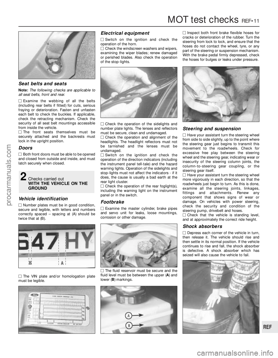
corr ectly spaced – spacing at (A) should be
twice that at (B).
M The VIN plate and/or homologation plate
must be legible.
Electrical equipment
M Switch on the ignition and check the
operation of the horn.
M Check the windscreen washers and wipers,
examining the wiper blades; renew damaged
or perished blades. Also check the operation
of the stop-lights.
M Check the operation of the sidelights and
number plate lights. The lenses and reflectors
must be secure, clean and undamaged.
M Check the operation and alignment of the
headlights. The headlight reflectors must not
be tarnished and the lenses must be
undamaged.
M Switch on the ignition and check the
operation of the direction indicators (including
the instrument panel tell-tale) and the hazard
war ning lights. Operation of the sidelights and
stop-lights must not affect the indicators - if it
does, the cause is usually a bad earth at the
r ear light cluster.
M Check the operation of the rear foglight(s),
including the warning light on the instrument
panel or in the switch.
Footbrake
M Examine the master cylinder, brake pipes
and servo unit for leaks, loose mountings,
corr osion or other damage.
M The fluid reservoir must be secure and the
fluid level must be between the upper ( A) and
lower ( B) markings. M
Inspect both front brake flexible hoses for
cracks or deterioration of the rubber . Turn the
steering from lock to lock, and ensure that the
hoses do not contact the wheel, tyre, or any
part of the steering or suspension mechanism.
With the brake pedal firmly depressed, check
the hoses for bulges or leaks under pressure.
Steering and suspension
M Have your assistant turn the steering wheel
fr om side to side slightly, up to the point where
the steering gear just begins to transmit this
movement to the roadwheels. Check for
excessive free play between the steering
wheel and the steering gear, indicating wear or
insecurity of the steering column joints, the
column-to-steering gear coupling, or the
steering gear itself.
M Have your assistant turn the steering wheel
mor e vigorously in each direction, so that the
r oadwheels just begin to turn. As this is done,
examine all the steering joints, linkages,
fittings and attachments. Renew any
component that shows signs of wear or
damage. On vehicles with power steering,
check the security and condition of the
steering pump, drivebelt and hoses.
M Check that the vehicle is standing level,
and at approximately the correct ride height.
Shock absorbers
M Depr ess each corner of the vehicle in turn,
then release it. The vehicle should rise and
then settle in its normal position. If the vehicle
continues to rise and fall, the shock absorber
is defective. A shock absorber which has
seized will also cause the vehicle to fail.
2Checks carried out
WITH THE VEHICLE ON THE
GROUND
procarmanuals.com
http://vnx.su
Page 280 of 296
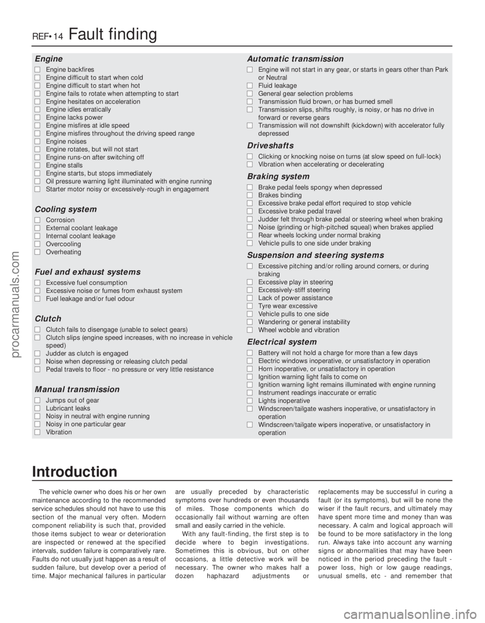
The vehicle owner who does his or her own
maintenance according to the recommended
service schedules should not have to use this
section of the manual very often. Modern
component reliability is such that, provided
those items subject to wear or deterioration
are inspected or renewed at the specified
intervals, sudden failure is comparatively rare.
Faults do not usually just happen as a result of
sudden failure, but develop over a period of
time. Major mechanical failures in particular are usually preceded by characteristic
symptoms over hundreds or even thousands
of miles. Those components which do
occasionally fail without warning are often
small and easily carried in the vehicle.
With any fault-finding, the first step is to
decide where to begin investigations.
Sometimes this is obvious, but on other
occasions, a little detective work will be
necessary. The owner who makes half a
dozen haphazard adjustments or replacements may be successful in curing a
fault (or its symptoms), but will be none the
wiser if the fault recurs, and ultimately may
have spent more time and money than was
necessary. A calm and logical approach will
be found to be more satisfactory in the long
run. Always take into account any warning
signs or abnormalities that may have been
noticed in the period preceding the fault -
power loss, high or low gauge readings,
unusual smells, etc - and remember that
Engine
m
m
Engine backfires
m
m Engine difficult to start when cold
m
m Engine difficult to start when hot
m
m Engine fails to rotate when attempting to start
m
m Engine hesitates on acceleration
m
m Engine idles erratically
m
m Engine lacks power
m
m Engine misfires at idle speed
m
m Engine misfires throughout the driving speed range
m
m Engine noises
m
m Engine rotates, but will not start
m
m Engine runs-on after switching off
m
m Engine stalls
m
m Engine starts, but stops immediately
m
m Oil pressure warning light illuminated with engine running
m
m Starter motor noisy or excessively-rough in engagement
Cooling system
m
mCorrosion
m
m External coolant leakage
m
m Internal coolant leakage
m
m Overcooling
m
m Overheating
Fuel and exhaust systems
m
mExcessive fuel consumption
m
m Excessive noise or fumes from exhaust system
m
m Fuel leakage and/or fuel odour
Clutch
m
mClutch fails to disengage (unable to select gears)
m
m Clutch slips (engine speed increases, with no increase in vehicle
speed)
m m Judder as clutch is engaged
m
m Noise when depressing or releasing clutch pedal
m
m Pedal travels to floor - no pressure or very little resistance
Manual transmission
m
mJumps out of gear
m
m Lubricant leaks
m
m Noisy in neutral with engine running
m
m Noisy in one particular gear
m
m Vibration
Automatic transmission
m
mEngine will not start in any gear, or starts in gears other than Park
or Neutral
m m Fluid leakage
m
m General gear selection problems
m
m Transmission fluid brown, or has burned smell
m
m Transmission slips, shifts roughly, is noisy, or has no drive in
forward or reverse gears
m m Transmission will not downshift (kickdown) with accelerator fully
depressed
Driveshafts
m mClicking or knocking noise on turns (at slow speed on full-lock)
m
m Vibration when accelerating or decelerating
Braking system
m
mBrake pedal feels spongy when depressed
m
m Brakes binding
m
m Excessive brake pedal effort required to stop vehicle
m
m Excessive brake pedal travel
m
m Judder felt through brake pedal or steering wheel when braking
m
m Noise (grinding or high-pitched squeal) when brakes applied
m
m Rear wheels locking under normal braking
m
m Vehicle pulls to one side under braking
Suspension and steering systems
m
mExcessive pitching and/or rolling around corners, or during
braking
m m Excessive play in steering
m
m Excessively-stiff steering
m
m Lack of power assistance
m
m Tyre wear excessive
m
m Vehicle pulls to one side
m
m Wandering or general instability
m
m Wheel wobble and vibration
Electrical system
m
mBattery will not hold a charge for more than a few days
m
m Electric windows inoperative, or unsatisfactory in operation
m
m Horn inoperative, or unsatisfactory in operation
m
m Ignition warning light fails to come on
m
m Ignition warning light remains illuminated with engine running
m
m Instrument readings inaccurate or erratic
m
m Lights inoperative
m
m Windscreen/tailgate washers inoperative, or unsatisfactory in
operation
m m Windscreen/tailgate wipers inoperative, or unsatisfactory in
operation
REF•14Fault finding
1595 Ford Fiesta Remake
Introduction
procarmanuals.com
http://vnx.su